Table of Contents
Advertisement
Quick Links
GE Consumer & Industrial
Multilin
GE Multilin
215 Anderson Avenue, Markham, Ontario
Canada L6E 1B3
Tel: (905) 294-6222 Fax: (905) 201-2098
Internet:
http://www.GEindustrial.com/multilin
1601-0164-A2
Courtesy of NationalSwitchgear.com
EPM 5100
Electronic Power Meter
INSTRUCTION MANUAL
Manual P/N: 1601-0164-A2
Manual Order Code: GEK-113391A
Copyright © 2008 GE Multilin
ISO9001:2000
GE Multilin's Quality Management
System is registered to ISO9001:2000
QMI # 005094
UL # A3775
Advertisement
Table of Contents

Related Manuals for GE EPM 5100


Summary of Contents for GE EPM 5100
- Page 1 Multilin EPM 5100 Electronic Power Meter INSTRUCTION MANUAL Manual P/N: 1601-0164-A2 Manual Order Code: GEK-113391A Copyright © 2008 GE Multilin ISO9001:2000 GE Multilin 215 Anderson Avenue, Markham, Ontario Canada L6E 1B3 GE Multilin's Quality Management System is registered to ISO9001:2000...
- Page 2 Courtesy of NationalSwitchgear.com...
-
Page 3: Table Of Contents
ALUES ......................3-2 EYPAD UNCTIONS ..................... 3-3 ETERING CCURACIES WYE CONFIGURATION METERING FUNCTIONS ..............3-4 ........................3-4 ESCRIPTION ) ........................3-4 URRENT ..........................3-4 OLTAGE ..........................3-4 OWER EPM 5100 ELECTRONIC POWER METER – USER GUIDE 4–1 Courtesy of NationalSwitchgear.com... - Page 4 LECTROMECHANICAL ETERS ................... 4-15 PGRADE ALCULATION XAMPLE CONFIGURATION ..........................4-16 ..........................4-16 PTIONS PT R ..........................4-16 ATIO CT R ..........................4-16 ATIO ....................4-17 EMAND ERIOD ETUP 4–2 EPM 5100 ELECTRONIC POWER METER – USER GUIDE Courtesy of NationalSwitchgear.com...
- Page 5 ORMAT ODES 6: MISCELLANEOUS TROUBLESHOOTING ........................6-1 ....................6-1 ROUBLESHOOTING UIDE REVISION HISTORY .......................... 6-4 ........................6-4 ELEASE ATES WARRANTY ............................6-5 GE M ....................6-5 ULTILIN ARRANTY EPM 5100 ELECTRONIC POWER METER – USER GUIDE 4–3 Courtesy of NationalSwitchgear.com...
- Page 6 CHAPTER 4: 4–4 EPM 5100 ELECTRONIC POWER METER – USER GUIDE Courtesy of NationalSwitchgear.com...
- Page 7 Overview Product Description The GE Multilin EPM 5100 Electronic Power Meter is a full-function electronic meter with optional pulse initiation and communications features. The communications option supports the ‘open-architecture’ Modbus protocol and can be easily installed in the field at a later date.
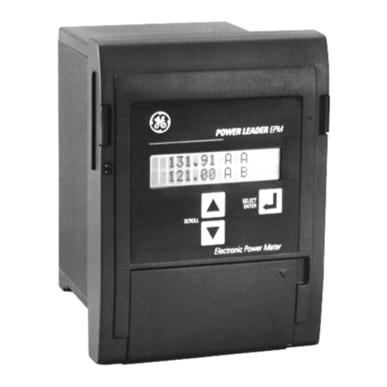
- Page 8 Open the door at the bottom of the front cover to adjust the display contrast or to view the list of measured parameters. FIGURE 1–1: EPM 5100 Meter 1–2 EPM 5100 ELECTRONIC POWER METER – USER GUIDE Courtesy of NationalSwitchgear.com...
-
Page 9: Features
Watthours, total Varhours, total lag (+) and total lead (–) Varhours, total lag (+) and total lead (–) VAhours, Total VAhours, total Frequency, in hertz Frequency, in hertz EPM 5100 ELECTRONIC POWER METER – USER GUIDE 1–3 Courtesy of NationalSwitchgear.com... -
Page 10: Power Management Features
Current Transformer Ratio 1.2.2 Power Management Features The EPM 5100 is available with the Power Leader communications options cards (catalog number PLA3CMAG01 for Modbus RTU). The Modbus option provides the following additional features: • Remote viewing of all metered functions and configuration data at the host computer. - Page 11 CHAPTER 1: OVERVIEW The following figure contains an example of a Power Leader power management system using the EPM 5100 and other Power Leader devices. 8000 Line Motor Control Center EPM Power Leader™ Meter Spectra RMS™ EPM Power Leader™ HOST...
-
Page 12: Physical Description
Any of the metered functions can be viewed by pressing the SCROLL buttons or allowing the EPM 5100 to automatically scroll through the parameters. All metered values are updated every three seconds, whether or not they are being displayed at the time. Press the SELECT/ button to toggle between the normal and alternate scrolls. -
Page 13: Panel Mounting
DS-65 electromechanical watthour meters. The case has four mounting holes that accept #10-32 × 3/8" (plus mounting panel thickness) screws. The meter is mounted through the front of the door or panel. The EPM 5100 may be installed on an existing DS-64 cutout using the PLE2ADPG01 adapter plate. -
Page 14: Dimensions, Case Type Unit
2.22" (56.4 mm) FIGURE 1–4: Panel Mounting Cutout Dimensions 1.3.5 Dimensions, Case Type Unit The front panel side views of the EPM 5100, case type unit, along with dimensions, are illustrated below 6.625" [168.3 mm] POWER LEADER EPM 9.125" SELECT ENTER [231.8mm]... -
Page 15: Dimensions, Panel Mounting Unit
[19.1 mm] 1.130" [33.3 mm] FIGURE 1–6: Side Dimensions, Case Type Unit 1.3.6 Dimensions, Panel Mounting Unit The front panel side views of the EPM 5100, panel mount unit, along with dimensions, are illustrated below 6.875" [174.63mm] 6.750" [171.45mm] 9.350" [237.5mm] FIGURE 1–7: Front Dimensions, Panel Mount Unit... - Page 16 CHAPTER 1: OVERVIEW 8.84" 9.5" 3.1" INSIDE PANEL 4.53" + PANEL THICKNESS FIGURE 1–8: Side Dimensions, Panel Mount Unit 1–10 EPM 5100 ELECTRONIC POWER METER – USER GUIDE Courtesy of NationalSwitchgear.com...
-
Page 17: Ordering
CHAPTER 1: OVERVIEW Ordering 1.4.1 Order Codes The order codes for the EPM 5100 Electronic Power Meter are shown below. Table 1–3: EPM 5100 Order Codes PLE3 – – – Base Unit PLE3 EPM 5100 Electronic Power Meter Case Type... -
Page 18: Applications
1.5.2 PT and CT Inputs The EPM 5100 Electronic Power Meter can be ordered to accept direct voltage inputs from 69 to 600 volts. For system voltages greater than 600 V, the customer must supply external PTs. The PT turns ratio is configured in Program mode and has a range of 0.5:1 to 9999:1. -
Page 19: Specifications
CT and PT terminals: ........recommend ring terminals to accommodate #10 screw, up to AWG #10 wire Pulse initiation port: ........two form-C contacts available at three-point terminal blocks; recommend bare, stranded copper wire, AWG #16-22 Communications port: .........EPM 5100 Electronic Power Meter standard six-position connector 1.6.3 Environmental ENVIRONMENTAL Operating temperature: ......–20°C to 70°C... - Page 20 CHAPTER 1: OVERVIEW 1–14 EPM 5100 ELECTRONIC POWER METER – USER GUIDE Courtesy of NationalSwitchgear.com...
-
Page 21: Installation Process
Table 6 is a matrix containing directions for the appropriate procedure to follow. For later field upgrade of a communication option card in an installed EPM 5100 Electronic Power Meter, see Installation of the Communications Card on page 2–15. - Page 22 The procedure for installing this plate requires 7/8" and 2-25/32" Greenlee hydraulic punches to make the necessary hole on the rear of the case. 2–2 EPM 5100 ELECTRONIC POWER METER – USER GUIDE Courtesy of NationalSwitchgear.com...
-
Page 23: Mechanical Installation
The word ‘panel’ here refers to panel or door, as appropriate. To make the panel cutout, first create a full-sized template according to the dimensions in FIGURE 1–4: Panel Mounting Cutout Dimensions on page 1–8. The procedure for mounting the EPM 5100 Electronic Power Meter is as follows: Cut out the panel and drill the holes as indicated on the template. -
Page 24: Retrofit Installation
The following procedure describes the process for replacing a DS-63 or DS-65 polyphase meter with an EPM 5100 Electronic Power Meter using the existing S1 case. If the pulse initiation and/or communication options are installed in the EPM 5100 Electronic Power Meter, see the above table for instructions. - Page 25 Open the locking latches at the top and bottom of the case and pull the existing electromechanical meter cradle part of the way out, as shown below. FIGURE 2–3: Opening the Locking Latches EPM 5100 ELECTRONIC POWER METER – USER GUIDE 2–5 Courtesy of NationalSwitchgear.com...
- Page 26 Remove the connection plug at the bottom of the EPM 5100 Electronic Power Meter. Open the locking latches at the top and bottom of the EPM 5100 Electronic Power Meter cradle assembly and pull the cradle part of the way out.
- Page 27 CHAPTER 2: INSTALLATION Unscrew the four mounting screws at the corners of the EPM 5100 Electronic Power Meter faceplate mounting frame and remove the frame, as shown below. FIGURE 2–6: Removing the Faceplate Mounting Frame Attach the EPM 5100 Electronic Power Meter faceplate mounting frame to the existing watthour meter case, reusing the mounting screws as shown below.
- Page 28 'panel' refers to panel or door, as appropriate. All current and voltage inputs (CTs and PTs) must be de-energized before the existing watthour meter case is removed and before connections are made to the EPM 5100 WARNING Electronic Power Meter.
- Page 29 Remove the existing watthour meter and case from the front of the panel. Insert the EPM 5100 Electronic Power Meter into the panel cutout from the front of the panel. Line up the four screw holes in the meter case with the holes drilled in the panel.
-
Page 30: Electrical Installation
PT connections must be made using the polarity “dot” conventions shown on these figures for the EPM 5100 Electronic Power Meter to properly interpret power flows. All current and voltage inputs (CTs and PTs) must be de-energized and the EPM 5100 Electronic Power Meter completely assembled before connections are made to the WARNING meter. - Page 31 CHAPTER 2: INSTALLATION Line Load FIGURE 2–11: Typical 2½-Element Connection with no PTs Line Load FIGURE 2–12: Typical 3-Element Connections with no PTs EPM 5100 ELECTRONIC POWER METER – USER GUIDE 2–11 Courtesy of NationalSwitchgear.com...
- Page 32 Connections shown with a dotted line are optional and do not affect the performance of the meter if installed or removed. This allows use of any existing wiring configuration when NOTE retrofitting a GE DS-63 or DS-65 electromechanical watthour meter. Line Load FIGURE 2–14: Typical 2½-Element Connections with Two PTs...
-
Page 33: Pulse Initiation Connections
2.3.2 Pulse Initiation Connections Connection to the optional pulse initiation circuits of the EPM 5100 is through the two three-point terminal points on the back of the case. The connection to these circuits, shown below, should be made at the same time as the current and voltage input connections. - Page 34 CHAPTER 2: INSTALLATION FIGURE 2–16: Three-Point Terminal Blocks for Pulse Initiation Outputs 2–14 EPM 5100 ELECTRONIC POWER METER – USER GUIDE Courtesy of NationalSwitchgear.com...
-
Page 35: Communications Installation
EPM 5100, refer to Chapter 5: Modbus Communications Features. Do not use the Modbus communications option card with a version 2 EPM 5100 unless a “Modbus Compatible” label is present on the case and/or cradle. If no “Modbus WARNING Compatible”... - Page 36 Insert the communication option card into the option card connector in the EPM 5100 by pressing the card into the connector at about a 300° angle, as illustrated below.
- Page 37 FIGURE 2–9: Aligning and Attaching the Faceplate on page 2–8. Follow the instructions in Communications Values on page 4–12 to configure the communication network address. EPM 5100 ELECTRONIC POWER METER – USER GUIDE 2–17 Courtesy of NationalSwitchgear.com...
- Page 38 CHAPTER 2: INSTALLATION 2–18 EPM 5100 ELECTRONIC POWER METER – USER GUIDE Courtesy of NationalSwitchgear.com...
-
Page 39: Meter Self-Test
Meter Operations 3.1.1 Meter Self-Test Each time that power is applied to the EPM 5100, it performs a self-test of its internal electronics. If there are no problems, the EPM 5100 displays the following message before entering into Metering mode:... -
Page 40: Communications Error
Table 1–2: EPM 5100 Metered Functions (ctd.) on page 1– 4, whether the EPM 5100 is in manual or automatic mode. If the meter is configured for automatic scrolling mode, it resumes one minute after the last scroll key press. -
Page 41: Metering Accuracies
CHAPTER 3: METERING The first press of any key while the EPM 5100 is in Metering mode illuminates the backlit display, if it is not already lit. The display remains illuminated for 10 minutes after the last key press. 3.1.6... -
Page 42: Wye Configuration Metering Functions
Following are descriptions of each of the metered values and status parameters available with the EPM 5100 in a wye configuration. Note that prefixes such as k or M depend on configuration, as described in Chapter 4. The suffixes A, B, C, and N generally refer to phase A, phase B, phase C, and neutral, respectively. -
Page 43: Apparent Power
LCD is exceeded. Values are identified on the LCD as Wh, VAh, Qh, +Varh (lagging), and -Varh (leading). 3.2.7 Frequency The frequency calculated by the EPM 5100 is identified on the LCD as Hertz. 3.2.8 Demand Current Demand (Present Ampere Demand) Current demand is the average rms current metered over the previous demand interval. -
Page 44: Power Factor
“Power Out”. 3.2.11 Transformer Ratios The potential transformer (PT) and current transformer (CT) ratios are identified on the LCD as “PTR” and “CTR”, respectively. 3–6 EPM 5100 ELECTRONIC POWER METER – USER GUIDE Courtesy of NationalSwitchgear.com... -
Page 45: Delta Configuration Metering Functions
Following are descriptions of each of the metered values and status parameters available with the EPM 5100 in a delta configuration. Note that prefixes such as k or M depend on configuration, as described in Chapter 4. The suffixes A, B, and C generally refer to phase A, phase B, and phase C, respectively. -
Page 46: Energy
Values are identified on the LCD as “Wh”, “VAh”, “Qh”, “+Varh” (lagging) and “–Varh” (leading). 3.3.6 Frequency The frequency calculated by the EPM 5100 is identified on the LCD as “Hertz”. 3.3.7 Demand Current Demand (Present Ampere Demand) Current demand is the average rms current metered over the previous demand interval. -
Page 47: Miscellaneous Functions
“Power Out”. 3.3.10 Transformer Ratios The potential transformer (PT) and current transformer (CT) ratios are identified on the LCD as “PTR” and “CTR”, respectively. EPM 5100 ELECTRONIC POWER METER – USER GUIDE 3–9 Courtesy of NationalSwitchgear.com... - Page 48 CHAPTER 3: METERING 3–10 EPM 5100 ELECTRONIC POWER METER – USER GUIDE Courtesy of NationalSwitchgear.com...
-
Page 49: Introduction
The EPM 5100 is configured to the application requirements in Program mode. This mode is also used to reset stored demand and energy values and to clear errors. Press the GE logo to activate the secret button and enter Program mode. -
Page 50: Access To Program Functions
“Configuration” functions is active, metering stops until control returns to the main menu. In addition, a return to the main menu from these functions automatically resets the demand interval time period. The other functions have no effect on metering. 4–2 EPM 5100 ELECTRONIC POWER METER – USER GUIDE Courtesy of NationalSwitchgear.com... -
Page 51: Restricted Access
Configuration → Access Restrict → New Password? Serial & Rev #s Meter Type Exit The display returns to the previous menu if the password is not entered correctly. EPM 5100 ELECTRONIC POWER METER – USER GUIDE 4–3 Courtesy of NationalSwitchgear.com... -
Page 52: Exiting Program Mode
Exiting Program Mode Each of the functions available in Program mode is described in this chapter. To return at any time to Metering mode, press the secret button (under the GE logo) or scroll to Exit and press ↵. Note that the latter method may have to be repeated to completely leave Program mode. -
Page 53: Description
Energy Reset Are you sure? To cancel the operation, press either the key. To confirm the reset operation, press ↵. The EPM 5100 displays the following text: Energy Reset Completed After three seconds, the display returns to: EPM 5100 ELECTRONIC POWER METER – USER GUIDE 4–5... -
Page 54: Meter Initialize
Meter Initialize Are you sure? To cancel the operation press either the key. To confirm the initialize operation, press ↵. The EPM 5100 displays the following text: Meter Initialize Completed After three seconds, the display returns to: Data Resetting →... -
Page 55: Data Formatting
The figures below illustrate a metering function with the pound sign displayed and the same function with the pound sign removed. FIGURE 4–3: Typical Scroll Sequence Display EPM 5100 ELECTRONIC POWER METER – USER GUIDE 4–7 Courtesy of NationalSwitchgear.com... - Page 56 # VA BC # Var A # VA # Var B # PF [Lag or Lead] # Var C # kWh # Var # +kVarh # VA A # -kVarh 4–8 EPM 5100 ELECTRONIC POWER METER – USER GUIDE Courtesy of NationalSwitchgear.com...
-
Page 57: Energy Format
X's. Either the key toggles that character among X, period (.), or blank. If X is chosen by pressing ↵, the cursor moves over one position and the same EPM 5100 ELECTRONIC POWER METER – USER GUIDE 4–9 Courtesy of NationalSwitchgear.com... -
Page 58: Voltage Format
Scroll between the two options, then press ↵ to select your choice. 4.4.8 Scroll Time Press ↵ to display the time that each parameter is displayed during automatic scroll in Metering mode: 4–10 EPM 5100 ELECTRONIC POWER METER – USER GUIDE Courtesy of NationalSwitchgear.com... - Page 59 ↵ to confirm. The default is 10 seconds. Set the scroll time to “00” to set the metering display to manual mode. In this mode, the keys must be used to change the displayed parameter. EPM 5100 ELECTRONIC POWER METER – USER GUIDE 4–11 Courtesy of NationalSwitchgear.com...
-
Page 60: Communications Values
Adjust sliders 3 and 4 (refer to the figure above) as indicated below for compatibility with the operating baud rate of the network: Table 4–2: Baud Rate Setup Baud Rate Slider 3 Slider 4 1200 2400 9600 19200 4–12 EPM 5100 ELECTRONIC POWER METER – USER GUIDE Courtesy of NationalSwitchgear.com... -
Page 61: Epm Compatibility Setup
The Modbus RTU Option Card, catalog number PLA3CMAG01, is compatible with GE ED&C host products in addition to the EPM 5100. For specific operation with the EPM 5100 it is necessary to select the compatible operating mode by switch settings on the communications option card. -
Page 62: Pulse Outputs
Pulse Outputs 4.6.1 Pulse Output Setup This function appears only if the pulse initiation option was ordered with the EPM 5100. There are two pulse initiation output channels that are set up with this function. The options available are: Output 1... -
Page 63: Upgrade Calculation Example
For example, a customer has a 480/277 V system (3 phase, 4-wire) with a 1600 A main. The watthour meter with pulse initiation is being replaced with a EPM 5100. The watthour meter was set for one pulse every ¼-disk revolution. The value to be programmed into the... -
Page 64: Configuration
Press ↵ to move to the right across the display, entering values in the appropriate positions with the keys. When the desired value is entered, continue pressing ↵ to return to the Configuration menu. 4–16 EPM 5100 ELECTRONIC POWER METER – USER GUIDE Courtesy of NationalSwitchgear.com... -
Page 65: Demand Period Setup
Set the desired block (Blk=) demand period and the subinterval (Sub=) for rolling demand calculations with the keys. Press ↵ to return to the Configuration menu. The EPM 5100 automatically adjusts the subinterval time choices according to the demand interval chosen. The available choices are listed below. Table 4–4: Demand Subintervals... -
Page 66: Restricted Access Functions
↵ to move to the second position. Continue until all six digits have been entered, after which the display returns to the New Password menu. 4–18 EPM 5100 ELECTRONIC POWER METER – USER GUIDE Courtesy of NationalSwitchgear.com... -
Page 67: Default Settings
CHAPTER 4: PROGRAMMING Default Settings 4.9.1 Description The following table lists the default settings for the EPM 5100 as shipped. Table 4–5: EPM 5100 Default Settings Parameter Default Setting Energy Format XXXXX.X K Demand Format XXXXXX Voltage Format XXXX.X Current Format XXXX.XX... - Page 68 CHAPTER 4: PROGRAMMING 4–20 EPM 5100 ELECTRONIC POWER METER – USER GUIDE Courtesy of NationalSwitchgear.com...
-
Page 69: Overview
Communications Introduction 5.1.1 Overview The tables in this chapter indicate the event codes and register maps of the EPM 5100. This section is intended only as a guide to the functions available with the device. 5.1.2 Events Events describe specific status conditions within the device and are available to the host computer either through the special DDE item, Events, or by direct read access of the registers containing the event information. -
Page 70: Modbus Register Maps
Failure 5.1.3 Modbus Register Maps The register map for the EPM 5100 are illustrated below. These tables list the registers that may be accessed by the host computer over the Modbus network. The registers are divided into four sections: Fixed value registers (addresses R40000 to R40009) - Page 71 Reactive power (kvar), phase A kvar R31054F KVAR_B Reactive power (kvar), phase B kvar R31056F KVAR_C Reactive power (kvar), phase C kvar R31058F KVA_A Apparent power (kVA), phase A EPM 5100 ELECTRONIC POWER METER – USER GUIDE 5–3 Courtesy of NationalSwitchgear.com...
- Page 72 Pulse value interval time for pulse KYZ output 2 0 to 999.999999 R43009 PULSE_UNIT_1 Pulse units for KYZ output 1 R43010 PULSE_UNIT_2 Pulse units for KYZ output 2 R43011L CONFIG_FLAG_1 Programming flags 5–4 EPM 5100 ELECTRONIC POWER METER – USER GUIDE Courtesy of NationalSwitchgear.com...
-
Page 73: Modbus Format Codes
B7: Energy data loss (<12hr) Bitmask: Voltage phase error B0: A-N voltage lost B1: B-N voltage lost B2: C-N voltage lost Enumeration: Leading/lagging 0 = lagging 1 = leading EPM 5100 ELECTRONIC POWER METER – USER GUIDE 5–5 Courtesy of NationalSwitchgear.com... - Page 74 65 ≡ XXXX.X 66 ≡ XXXX.XX 80 ≡ XXXXX 81 ≡ XXXXX.X 96 ≡ XXXXXX Enumeration: Display scale 32 ≡ unit (×10 77 ≡ M (×10 107 ≡ k (×10 5–6 EPM 5100 ELECTRONIC POWER METER – USER GUIDE Courtesy of NationalSwitchgear.com...
- Page 75 5: D0h 6: CFh 7: CEh 8: CDh 9: CCh For example, 12-34-56 would be encoded as D4D3D2D1D0CFh Enumeration: Command Coil 0 ≡ Disable command 1 ≡ Perform command EPM 5100 ELECTRONIC POWER METER – USER GUIDE 5–7 Courtesy of NationalSwitchgear.com...
- Page 76 CHAPTER 5: COMMUNICATIONS 5–8 EPM 5100 ELECTRONIC POWER METER – USER GUIDE Courtesy of NationalSwitchgear.com...
-
Page 77: Troubleshooting Guide
WARNING Symptom: The vars reading is erratic and does not reflect a stable value. Possible Cause: There is no voltage and/or current at the inputs and the EPM 5100 is seeing random noise. Corrective Action: Apply current or voltage, or lower the PT or CT ratios of the unused input. - Page 78 Possible Cause: The self-test detected a critical failure in the meter electronics. Corrective Action: Run the self-test again by removing and reapplying power. If the same failure message reappears, contact GE Multilin. Symptom: The error message, Phase Loss V, is displayed.
- Page 79 Possible Cause: Severe physical trauma to front or case of meter. Corrective Action: Order replacement case or replacement parts pack from GE Multilin. The catalog number for the replacement case is PLE2CSEG01. The catalog number for the replacement parts pack is PLE2RPG01. The replacement parts pack contains a faceplate with label and display electronics and a frame with gasket and four mounting screws.
-
Page 80: Revision History
CHAPTER 6: MISCELLANEOUS Revision History 6.2.1 Release Dates Table 6–1: Release Dates MANUAL GE PART NO. REVISION RELEASE DATE GEK-106646 1601-0164-A1 1.0x July 27, 2007 6–4 EPM 5100 ELECTRONIC POWER METER – USER GUIDE Courtesy of NationalSwitchgear.com... -
Page 81: Warranty
In the event of a failure covered by warranty, GE Multilin will undertake to repair or replace the device providing the warrantor determined that it is defective and it is returned with all transportation charges prepaid to an authorized service centre or the factory. - Page 82 CHAPTER 6: MISCELLANEOUS 6–6 EPM 5100 ELECTRONIC POWER METER – USER GUIDE Courtesy of NationalSwitchgear.com...
- Page 83 1-13 CURRENT TRANFORMERS connections ..............................2-10 CURRENT TRANSFORMERS ratio ................................. 4-16 DATA FORMATTING..............................4-7 DEFAULT SETTINGS............................. 4-19 DEMAND format................................4-9 metering..............................3-5, 3-8 Modbus registers............................5-3 period setup ..............................4-17 EPM 5100 ELECTRONIC POWER METER – USER GUIDE 4–1 Courtesy of NationalSwitchgear.com...
- Page 84 2-4, 2-8 INSTRUMENT TRANSFORMER CONNECTIONS..................2-10 INTEGRITY...................................3-1 INTERCONNECTIONS............................1-13 INTRODUCTION ...............................1-1 KEYPAD..................................3-2 KYZ PULSE WEIGHT ............................4-14 LEADING ZEROS ..............................4-10 MECHANICAL INSTALLATION..........................2-3 METER INITIALIZE..............................4-6 METER TYPE................................4-17 METERED FUNCTIONS ..........................1-3, 1-4 4–2 EPM 5100 ELECTRONIC POWER METER – USER GUIDE Courtesy of NationalSwitchgear.com...
- Page 85 Modbus registers..........................5-3, 5-4 PROGRAM MODE ..............................4-1 PT RATIO applications ..............................1-12 metering................................3-6 Modbus registers............................5-5 setting................................4-16 PULSE INITIATION connections ..............................2-13 PULSE OUTPUTS Modbus registers............................5-4 setup ................................4-14 EPM 5100 ELECTRONIC POWER METER – USER GUIDE 4–3 Courtesy of NationalSwitchgear.com...
- Page 86 TRANSFORMER RATIOS ..........................3-6, 3-9 TROUBLESHOOTING..............................6-1 TYPE TESTS................................1-13 UL LISTING ................................1-13 UPGRADING FROM ELECTROMECHANICAL METERS ................4-14 VOLTAGE format................................4-10 metering..............................3-4, 3-7 Modbus registers............................5-4 specifications ..............................1-13 WARRANTY ................................6-5 WYE CONFIGURATION METERING........................3-4 4–4 EPM 5100 ELECTRONIC POWER METER – USER GUIDE Courtesy of NationalSwitchgear.com...