Epson RC620 Safety And Installation
Hide thumbs
Also See for RC620:
- Manual (220 pages) ,
- Safety and installation (218 pages) ,
- Mounting procedure (2 pages)
Table of Contents
Advertisement
Quick Links
Advertisement
Table of Contents

Related Manuals for Epson RC620


Summary of Contents for Epson RC620
- Page 1 RC620 Safety and Installation Read this manual first Rev.8 EM121B2281F...
- Page 3 C620 Safety and Installation ev.8 Copyright © 2009-2012 SEIKO EPSON CORPORATION. All rights reserved. RC620 Safety and Installation Rev.8...
- Page 4 3. We cannot foresee all possible dangers and consequences. Therefore, this manual cannot warn the user of all possible hazards. RC620 Safety and Installation Rev.8...
- Page 5 Please prepare the following items before you contact us. - Your controller model and its serial number - Your manipulator model and its serial number - Software and its version in your robot system - A description of the problem SERVICE CENTER RC620 Safety and Installation Rev.8...
- Page 6 Otto-Hahn-Str.4, D-40670 Meerbusch, Germany : +49-(0)-2159-538-1391 : +49-(0)-2159-538-3170 E-MAIL : robot.infos@epson.de China EPSON China Co., Ltd Factory Automation Division 7F, Jinbao Building No. 89 Jinbao Street Dongcheng District, Beijing China, 100005 : +86-(0)-10-8522-1199 : +86-(0)-10-8522-1120 RC620 Safety and Installation Rev.8...
- Page 7 Taiwan EPSON Taiwan Technology & Trading Ltd. Factory Automation Division 14F, No.7, Song Ren Road, Taipei 110 Taiwan, ROC : +886-(0)-2-8786-6688 : +886-(0)-2-8786-6677 Southeast Asia Epson Singapore Pte Ltd. India Factory Automation System 1 HarbourFrontPlace, #03-02 HarbourFront Tower one, Singapore...
- Page 8 For other countries, please contact your local government to investigate the possibility of recycling your product. The battery removal/replacement procedure is described in the following manuals: Controller manual / Manipulator manual (Maintenance section) RC620 Safety and Installation Rev.8...
- Page 9 When using the TP1 with the RC180, refer to theRC180 Option Teach Pendant TP1. Do not connect the followings to the TP port of RC620. Connecting to the followings may result in malfunction of the device since the pin assignments are different.
-
Page 10: Table Of Contents
2.9 Drive Unit Configuration············································ 81 2.10 Connecting Manipulator and Controller ·················· 82 2.11 Power-on ··································································· 84 3. First Step 3.1 Installing EPSON RC+ 5.0 Software························· 86 3.2 Writing your first program·········································· 93 4. Second Step 4.1 Connection with External Equipment ······················ 100 ···········... - Page 11 5. General Maintenance 5.1 Schedule for Maintenance Inspection ··················102 5.2 Inspection Point ··············································104 6. Manuals 7. Directives and Norms RC620 Safety and Installation Rev.8...
- Page 12 RC620 Safety and Installation Rev.8...
-
Page 13: Safety
WARNING This symbol indicates that a danger of possible harm to people or physical damage to equipment and facilities exists if the associated instructions are not followed properly. CAUTION RC620 Safety and Installation Rev.8... -
Page 14: Design And Installation Safety
The following items are safety precautions for design personnel: ■ Personnel who design and/or construct the robot system with this product must read the Safety chapter in the EPSON RC+ User’s Guide to understand the safety requirements before designing and/or constructing the robot system. -
Page 15: Operation Safety
The following items are safety precautions for qualified Operator personnel: ■ Please carefully read the Safety-related Requirements in the Safety chapter of the EPSON RC+ User’s Guide before operating the robot system. Operating the robot system without understanding the safety requirements is extremely hazardous and may result in serious bodily injury and/or severe equipment damage to the robot system. - Page 16 Part 1. Specification for general requirements EN55011 Limits and methods of measurement of radio disturbance characteristic of industrial scientific and medical (ISM) radio frequency equipment. EN61000-6-2 Electromagnetic compatibility (EMC) Part 6-2: Generic standards - Immunity for industrial environments RC620 Safety and Installation Rev.8...
- Page 17 The motion range of each arm is shown in the figure below. Take all necessary safety precautions. Joint #2 (Rotate) Joint #1 (Rotate) Arm #2 Shaft Joint #3 (Up/Down) Arm #1 Joint #4 (Figure of G6553S) (Rotate) RC620 Safety and Installation Rev.8...
- Page 18 The motion range of each arm is shown in the figure below. Take all necessary safety precautions. Joint #1 (rotating) − Joint #2 (rotating) − Base Arm #1 Arm #2 Joint #3 − Shaft (up and down) − Joint #4 (Figure of RS3-351*) (rotating) RC620 Safety and Installation Rev.8...
- Page 19 Joint #1 : The whole Manipulator revolves. Joint #2 : The lower arm swings. Joint #3 : The upper arm swings. J1− Joint #4 : The wrist revolves. Base Joint #5 : The wrist swings. Joint #6 : The wrist rotates. RC620 Safety and Installation Rev.8...
- Page 20 Joint #2 : The lower arm swings. Joint #3 : The upper arm swings. Joint #4 : The wrist revolves. Joint #1 Joint #5 : The wrist swings. Base Joint #6 : The wrist rotates. RC620 Safety and Installation Rev.8...
- Page 21 Arm #4 : The wrist revolves. Base Arm #5 : The wrist swings. Arm #6 : The wrist rotates. X5 series The operation varies with different module combination. For details, refer to the EZ Module X5 Series manual. RC620 Safety and Installation Rev.8...
-
Page 22: Maintenance Safety
Operating the robot system when the switches do not function properly is extremely hazardous and may result in serious bodily injury and/or serious damage to the robot system as the switches cannot fulfill their intended functions in an emergency. RC620 Safety and Installation Rev.8... - Page 23 - If alcohol, liquid gasket, or adhesive gets into your eyes or mouth, flush your eyes or wash out your mouth with clean water thoroughly, and then see a doctor immediately. RC620 Safety and Installation Rev.8...
- Page 24 If swallowed, do not induce vomiting. See a doctor immediately. If grease just gets into your mouth, wash out your mouth with water thoroughly. If grease gets on your skin: Wash the area thoroughly with soap and water. RC620 Safety and Installation Rev.8...
-
Page 25: Emergency Stop
Robot system safely. Do not tear, damage, or remove the labels. Use meticulous care when handling those parts or units to which the following labels are attached as well as the nearby areas: RC620 Safety and Installation Rev.8... - Page 26 TP port of RC620. Connecting to the followings may result malfunction device. OPTIONAL DEVICE dummy plug, OP500, OP500RC, JP500, OP1 and TP-3**, and TP2 Refer to 4.2 Connection and Display Language of Option TP1 Controller Drive Unit RC620 Safety and Installation Rev.8...
- Page 27 OPTIONAL DEVICE dummy plug, OP500, OP500RC, OP1, JP500, TP-3**, and TP2 Refer to 4.2 Connection and Display Language of Option TP1 Controller Drive Unit RC620 Safety and Installation Rev.8...
- Page 28 You can catch your hand or fingers between the shaft and cover when bringing your hand close moving parts. Manipulators with bellows do not have this label for no danger of your hand or fingers being caught RC620 Safety and Installation Rev.8...
- Page 29 Do not lift without the shipping bracket. To pick up the manipulator arm, use two wire ropes of equal length. Remove the shipping brackets and eyebolts before turning power Follow the directions this manual installation transportation. RC620 Safety and Installation Rev.8...
- Page 30 When these operations are performed by unauthorized personnel, it is extremely hazardous and may result in serious bodily injury and/or severe equipment damage to the robot system. RC620 Safety and Installation Rev.8...
- Page 31 This is extremely hazardous and may result in serious safety problems. Hazardous voltage exists while the Manipulator is ON. To avoid electric shock, do not touch any internal electric parts. RC620 Safety and Installation Rev.8...
- Page 32 Do not lift without the shipping bracket. To pick up the manipulator arm, use two wire ropes of equal length. Remove the shipping brackets and eyebolts before turning power on. Follow the directions in this manual for installation and transportation. RC620 Safety and Installation Rev.8...
- Page 33 1. Safety Location Label Note Arm weight may cause arm to fall during disassembly operation. Follow the directions in this manual for disassembly operation. RC620 Safety and Installation Rev.8...
- Page 34 1. Safety Location of Labels Common Table Top Mounting Multiple Mounting RC620 Safety and Installation Rev.8...
- Page 35 1. Safety Table Top Mounting G6-***S Wall Mounting Ceiling Mounting G6-***SR G6-***SW RC620 Safety and Installation Rev.8...
- Page 36 1. Safety G10/G20 Table Top Mounting: G10/G20-**** Wall Mounting: G10/G20-****W Ceiling Mounting: G10/G20-****R RC620 Safety and Installation Rev.8...
- Page 37 1. Safety RS series Side B (Both sides) Front Bottom RC620 Safety and Installation Rev.8...
- Page 38 1. Safety Top View Back View Front View Lateral View RC620 Safety and Installation Rev.8...
- Page 39 1. Safety Lateral View (Left side) Lateral View (Right side) Back View Front View RC620 Safety and Installation Rev.8...
- Page 40 1. Safety PS series Top View Back View Lateral View (Left side) Lateral View (Right side) Front View RC620 Safety and Installation Rev.8...
- Page 41 1. Safety NOTE Label E is for the manipulator of up/down axis. RC620 Safety and Installation Rev.8...
-
Page 42: Safety Features
Teach Pendant to the “Teach” mode. Manipulator operation is available only when the enable switch is on. In this case, the Manipulator is operated in low power status. RC620 Safety and Installation Rev.8... - Page 43 Positioning Overflow -Servo Error- Detection The dynamic brake circuit is activated when the system detects that the difference between the Manipulator’s actual position and commanded position exceeds the margin of error allowed. RC620 Safety and Installation Rev.8...
- Page 44 The dynamic brake circuit is activated when the drop of the power supply voltage is detected. Temperature Anomaly Detection The temperature anomaly is detected. Fan Malfunction Detection Malfunction of the fan rotation speed is detected. RC620 Safety and Installation Rev.8...
-
Page 45: Installation
The outline to install the robot system is indicated on 2.1 Outline from Unpacking to Operation of Robot System. Refer to each section and/or the Manipulator manual and the Controller manual for unpacking, transportation, and installation. RC620 Safety and Installation Rev.8... -
Page 46: System Example
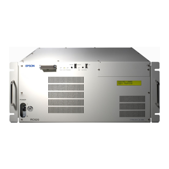
Frame Grubber Board Fieldbus I/O Master Board EPSON RC+ 6.0 PROFIBUS-DP DeviceNET Vision Guide 6.0 (option) EtherNet/IP VB Guide 6.0 PS series (option) S5 series GUI Builder 6.0 (option) Display Keyboard Mouse Additional axis (option) RC620 Safety and Installation Rev.8... - Page 47 Drive Unit is the auxiliary unit connected with the control unit using the special cable. Drive Unit cannot operate alone. One or Two Drive Unit(s) can be used per robot system. RC620 Control Unit can be described as RC620CU (Control Unit) to distinguish from RC620DU (Drive Unit). RC620 Safety and Installation Rev.8...
-
Page 48: Outline From Unpacking To Operation Of Robot System
ON the power properly 3. First Step Procedures to install EPSON RC+6.0 to the development PC and enable the operation of the robot system 4. Second Step Manual information to connect or setup the equipment and options RC620 Safety and Installation Rev.8... -
Page 49: Unpacking
Wire tie : Do not remove the wire tie securing the arm until you finish the installation. You may get your hands caught in the Manipulator when the wire tie is removed before completing the installation. RC620 Safety and Installation Rev.8... -
Page 50: Transportation
: Stabilize the Manipulator with your hands when hoisting it. Unstable hoisting is extremely hazardous and may results in serious bodily injury and/or severe equipment damage to the robot system as the fall of the Manipulator. RC620 Safety and Installation Rev.8... - Page 51 G3-301*M : approx. 14 kg: 31 lb. G3-351*M : approx. 14 kg: 31 lb Table Top Mounting G3-251* : approx. 14 kg: 31 lb. G3-301* : approx. 14 kg: 31 lb. G3-351* : approx. 14 kg: 31 lb. RC620 Safety and Installation Rev.8...
- Page 52 When holding the bottom of the base by hand, be very careful not to get your hands or fingers caught. RS3-351* : approx. 17 kg : 38 lb. (except cables) RS4-551* : approx. 19 kg : 42 lb. (except cables) RC620 Safety and Installation Rev.8...
- Page 53 : Approx. 48 kg : 106 lb 85**W : Approx. 53 kg : 117 lb Table Top Mounting: * A0**/**R : Approx. 50 kg : 111 lb Ceiling Mounting: R A0**W : Approx. 55 kg : 122 lb RC620 Safety and Installation Rev.8...
- Page 54 Do not hold the bottom of the base (the screened parts in the figure). Holding these parts by hand is extremely hazardous and may cause your hands and fingers to be caught. Manipulator weight : 27 kg (59.5 lb.) DO NOT hold the bottom of the base by hand. RC620 Safety and Installation Rev.8...
- Page 55 S5-A701** Approx. 38 kg (Manipulator weight: 36 kg (80 lb.)) S5-A901** Approx. 40 kg (Manipulator weight: 38 kg (84 lb.)) Shipping bolts and jigs DO NOT hold the bottom of the base by hand. RC620 Safety and Installation Rev.8...
- Page 56 To avoid colliding while transporting, use ropes or fittings to secure parts. - Basically, transport the manipulator on module basis. Module body weight RH module Max. 61 kg RM module Max. 17 kg RSz module Max. 8.3 kg RU module 2.6 kg Main unit Motor RC620 Safety and Installation Rev.8...
- Page 57 The pallet must have enough strength to bear the weight of the Manipulator. Transporting of the Manipulator must be performed slowly in order to avoid overturning or slippage. 18° 45° Bolt (4-M10) Controller Pallet Inset here the forklift claws. (Figures of PS3) RC620 Safety and Installation Rev.8...
-
Page 58: Manipulator Installation
: To ensure safety, a safeguard must be installed for the robot system. For details on the safeguard, refer to the Installation and Design Precautions in the Safety chapter of the EPSON RC+ User’s Guide. Space between safeguard and Manipulator... - Page 59 50% RP-HMSz 76.2 RU-HMSz 76.2 Under rated load, PS3 PS3L PS5 72.8 All arm simultaneous 1000mm apart from operation, maximum speed, the Back of the Manipulator maximum acceleration, and duty 50% RC620 Safety and Installation Rev.8...
- Page 60 Threaded holes for Mounting screw The plate for the Manipulator mounting face should be 30 mm thick or more and made of steel to reduce vibration. The surface roughness of the steel plate should be 25 μm or less. RC620 Safety and Installation Rev.8...
- Page 61 The table must be secured on the floor or wall to prevent it from moving. The Manipulator must be installed horizontally. When using a leveler to adjust the height of the base table, use a screw with M16 diameter. RC620 Safety and Installation Rev.8...
- Page 62 M6 size (Length: 25 mm + Spring washer + Plain washer) conforming to the strength, ISO898-1 property class: 6.9. Secure outward four points. G1-171* : approx. 8 kg :18 lb. G1-221* : approx. 8 kg :18 lb. RC620 Safety and Installation Rev.8...
- Page 63 (3) Remove the bolts securing the wire ties removed in step (2). Wire tie Bolt (4) Remove the shipping bolt and :M4×15 jigs. Sheet RC620 Safety and Installation Rev.8...
- Page 64 Screw Hole (depth 20 mm or more) four bolts. Use bolts with specifications NOTE conforming to ISO898-1 Property 10 mm Plane Washer Class: 10.9 or 12.9. Spring Washer (3) Remove the shipping bolt and 4-M8×30 jigs. RC620 Safety and Installation Rev.8...
- Page 65 Bolt :M4×15 (3) Remove the bolts securing the wire ties Sheet removed in step (2). Wire tie Bolt (4) Remove the shipping bolt and jigs. :M5×15 RC620 Safety and Installation Rev.8...
- Page 66 20 mm Use bolts with specifications NOTE conforming to ISO898-1 Property Screw Hole (depth Class: 10.9 or 12.9. 20 mm or more) (3) Remove the shipping bolt and jigs. Plane Washer × Spring Washer 4-M8 40 RC620 Safety and Installation Rev.8...
- Page 67 Screw Hole bolts. (depth 20 mm or more) 20 mm Use bolts with specifications NOTE Plane conforming to ISO898-1 Property Washer Spring Class: 10.9 or 12.9. Washer 4-M8×40 (3) Remove the shipping bolt and jigs. RC620 Safety and Installation Rev.8...
- Page 68 Washer : M6 base. Wire tie Remove the bolts securing the wire ties removed in step (2). Arm mounting bolt (4) Remove the shipping bolt and jigs. : M12×20 Eyebolt (Attached at shipment) RC620 Safety and Installation Rev.8...
- Page 69 (2) Secure the base to the wall with six bolts. NOTE Use bolts with specifications conforming 20 mm to ISO898-1 Property Class: 10.9 or 12.9. Screw Hole (3) Remove the shipping bolt and jigs. (depth 20 mm or more) Plane Washer Spring Washer 6-M12×40 RC620 Safety and Installation Rev.8...
- Page 70 Screw Hole bolts. (depth 20 mm or more) 20 mm Plane Use bolts with specifications conforming NOTE Washer to ISO898-1 Property Class: 10.9 or 12.9. Spring Washer 4-M12×40 (3) Remove the shipping bolt and jigs. RC620 Safety and Installation Rev.8...
- Page 71 (2) Secure the base to the wall with 6 Screw hole bolts. (Depth: 12 mm or more) Intensity of the bolts should be NOTE equivalent to ISO898-1 Property Class 10.9 or 12.9. (3) Remove the shipping bolt and jigs. 6-M6×20 RC620 Safety and Installation Rev.8...
- Page 72 The shipping bolts and jigs must then be stored for future use, in the event that the Manipulator must be moved again. There are 4 threaded holes for the Manipulator base. Use M8 mounting bolts (Length: 40 mm) conforming to the strength, ISO898-1 property class: 12.9. RC620 Safety and Installation Rev.8...
- Page 73 - In addition, using ø8H7 hole on the back side of the body, you can decide where to secure. In this case, see the figure below for the pin on the base table. RC620 Safety and Installation Rev.8...
- Page 74 RM550 : 2 Units to use RH800 : 3 RM750 : 3 RM750 : 2 RH1000 : 3 Weight approx. 2.4 kg approx.1.8 kg approx.3.6 kg RG-HM RG-MS Applicable module RD-HM YZ-MS RD-MS RP-HMSz RP-MSSz RU-HMSz RC620 Safety and Installation Rev.8...
-
Page 75: Controller Installation
Damaged cables, disconnection, or a contact failure is extremely hazardous and may result in electric shock and/or improper function of the system. RC620 Safety and Installation Rev.8... - Page 76 There must also be room behind the Controller so that one can attach and remove cables. Use a base table that is at least 100 mm off the floor. Placing the Controller directly on the floor could allow dust penetration leading to malfunction. RC620 Safety and Installation Rev.8...
- Page 77 The length from the edge of fixture L differs by the side. Refer to the following NOTE figure and mount the side with shorter distance from the edge to the screw hole on the Upper side. RC620 Safety and Installation Rev.8...
- Page 78 When mounting direction is (C) : Fixture S (Front Side) (Front Side) Drive unit Drive unit only + ProSix Driver Unit - No screw hole processing is required for mounting direction (D). Secure it to the rack with screws and nuts. RC620 Safety and Installation Rev.8...
- Page 79 - Hot air with higher temperature than the ambient temperature (about 10 deg.C) comes out from the Drive unit. Make sure that heat sensitive devices are not placed near the outlet. RC620 Safety and Installation Rev.8...
-
Page 80: Connecting To Emergency Connector
Emergency Stop switch. Be sure to use these input terminals to keep the system safe. Connector Standard EMERGENCY connector D-sub25 Pin (male) (Controller / DriveUnit side) Mounting style #4-40 * The E-STOP BOX, connector cable, terminal block, and connector kit are offered as options. RC620 Safety and Installation Rev.8... - Page 81 The controller software latches the following conditions: - The safety door is open. - The operation mode is “TEACH”. The EMERGENCY connector has an input terminal for a latch release switch that cancels the latched conditions. RC620 Safety and Installation Rev.8...
- Page 82 The latch release input also functions to acknowledge the change of TEACH mode. In order to change the latched condition of the TEACH mode, turn the mode selector key switch on the Teach Pendant to “Auto”. Then, close the latch release input. RC620 Safety and Installation Rev.8...
- Page 83 Therefore, make sure that the Emergency Stop switch has double contacts and that each circuit connects to the specified pins on the EMERGENCY connector at the Controller. Refer to the RC620 Controller Manual: Setup & Operation 8.4 Circuit Diagrams.
- Page 84 Latch Release rated input voltage range 18-19 pin Latch Release rated input current 10 mA/+24 V input The total electrical resistance of the Emergency Stop switches and their circuit should NOTE be 1 Ω or less. RC620 Safety and Installation Rev.8...
- Page 85 Motor Driver AC Input Emergency Stop detection External +24V Safety Door input 1 Safety Door input 2 Latch release input External +24V Latch release input Close :Latch off NOTE:+24V GND Open :Latch on + 5V GND RC620 Safety and Installation Rev.8...
- Page 86 Emergency Stop detection External +24V External +24V Safety Door input 1 Safety Door input 2 Latch Release input External + 24V Latch release input Close :Latch off NOTE:+24V GND Open :Latch on + 5V GND RC620 Safety and Installation Rev.8...
- Page 87 2. Installation Circuit Diagrams – Drive Unit Circuit Diagram Drive Unit Main Circuit Control Emergency Stop detection Safety Door input 1 Safety Door input 2 Latch release input RC620 Safety and Installation Rev.8...
- Page 88 Emergency stop switch of an Operation unit Terminal block NOTE - The Emergency cable, Emergency cable kit, and Terminal block are offered as options. - Design the cables connecting the units within 20 m long. RC620 Safety and Installation Rev.8...
- Page 89 +24V External +24V External +24V Terminal block * Fuse For the protection of the emergency stop circuit, the fuse’s capacity should be as follows: - Meets the capacity of the external - 0.4A or less RC620 Safety and Installation Rev.8...
- Page 90 Safety Door input 1 Safety Door input 2 Latch release input Safety Door input 1 Safety Door input 2 Latch release input External NOTE - Design the cables connecting the units within 20 m long. RC620 Safety and Installation Rev.8...
-
Page 91: Ac Power Cable
AC power supplying side in accordance with the National Electrical Code. A disconnecting means shall be installed in accordance with the WARNING National Electrical Code and provide the ability for lockout and tagout. RC620 Safety and Installation Rev.8... -
Page 92: Drive Unit Connection
- Do not use any LAN cables on the market. Otherwise, it results in the robot controller malfunction. How to turn on the power switch: Check the connection first. Then, make sure to turn on the power switch of Drive Unit before turning on the power switch of Control Unit. RC620 Safety and Installation Rev.8... -
Page 93: Drive Unit Configuration
Inlet Plate Plastic Fasteners Change the DIP swich in SMB. Drive Unit ALL OFF DIP switch 1 2 3 4 Drive Unit ON : 1 OFF : 2, 3, 4 1 2 3 4 RC620 Safety and Installation Rev.8... -
Page 94: Connecting Manipulator And Controller
The unnecessary strain on the cables may result in damage to the cables, disconnection, and/or contact failure. Damaged cables, disconnection, or contact failure is extremely hazardous and may result in electric shock and/or improper function of the robot system. RC620 Safety and Installation Rev.8... - Page 95 Manipulator without connecting them may result in electric shock and/or malfunction of the robot system as it cannot ensure IP65. Connect the Manipulator to the Controller using the Power cable and the Signal NOTE cable. RC620 Safety and Installation Rev.8...
-
Page 96: Power-On
Turn ON the Drive Unit RC620DU POWER switch. * Turn ON the Control Unit RC620CU POWER switch. * * For RC620-UL and RC620DU-UL, the POWER switch is not available. Instead, turn ON the external disconnecting means. RC620 Safety and Installation Rev.8... - Page 97 When an error appears, check the connection in step (1) to (5) to turn ON the power again. If an error appears after checking the connection, contact the supplier. Control Unit (8) LCD RC620CU (7) POWER switch Drive Unit RC620DU (6) POWER switch RC620 Safety and Installation Rev.8...
-
Page 98: First Step
Auto Start. NOTE When using the VB Guide option, you do not need to start EPSON RC+ 6.0. The library provided with VB Guide will load EPSON RC+ 6.0 into your .NET application process automatically. - Page 99 If no tasks are currently running, a dialog below will be displayed. For sessions > 1 EPSON RC+ should be started in Off-line mode. If there are no project files specified on the startup command line, then the last project that was opened will be opened as read only at startup time.
- Page 100 Real Part and Windows Part are started up separately at the each timing. To operate the robot system without problem, you should synchronize these two parts. At the shipment of RC620 robot controller, the Cooperative mode that synchronizes these parts is applied.
- Page 101 How to set the Independent mode (1) Select the Setup | System Configuration from the main menu and displays the [System Configuration] dialog as shown below. (2) Select the SPEL Controller Board | Preferences. RC620 Safety and Installation Rev.8...
- Page 102 To configure startup, select the [System Configuration] from the Setup Menu. The Startup section has pages for Start Mode, Auto Start, and Windows Login. Start Mode This page has settings for the EPSON RC+ 6.0 start mode. There are two start modes: Program This mode allows you to develop your projects.
- Page 103 NOTE When you change to PROGRAM mode from this dialog, it is only temporary. The next time EPSON RC+ 6.0 runs, the original start mode setting will be used. Start Mode: Program Program mode is the default start mode.
- Page 104 Auto Start You can configure EPSON RC+ 6.0 to automatically start when Windows starts. From the Setup | System Configuration | Auto Start page, set the Start EPSON RC+ 6.0 after Windows start check box. In addition, if you set the checkbox above, you can specify EPSON RC+ 6.0 command line options (/auto, /nosplash, etc.) in the Command line options text...
-
Page 105: Writing Your First Program
3. First Step 3.2 Writing your first program After installing the RC620 controller, robot, and EPSON RC+ 6.0 software on your PC, follow these instructions to create a simple application program so that you will become more familiar with the EPSON RC+ 6.0 development environment. - Page 106 3. First Step 3. Edit the program Type in the following program lines in the Main.prg edit window. Function main Print "This is my first program." Fend RC620 Safety and Installation Rev.8...
- Page 107 (4) You should see text similar to the following displayed in the Status window: 19:32:45 Task main started 19:32:45 All tasks stopped On the Run window, you will see the output of the print statement. RC620 Safety and Installation Rev.8...
- Page 108 You will see the Robot Manager window with the Control Panel page displayed. (2) Click on the Motor On button to turn on the robot motors. You will be prompted to confirm the operation. Answer Yes to continue. RC620 Safety and Installation Rev.8...
- Page 109 (11) Change the current point to P2 by selecting P2 in the Point dropdown list. (12) Click the Teach button. You will see a confirmation message to teach the point. Answer Yes. (13) Click the Save Project toolbar button to save the changes. RC620 Safety and Installation Rev.8...
- Page 110 8. Backup the project and system configuration Even though this is only a sample project, we will backup the project and controller configuration. This is easy to do with EPSON RC+ 6.0. It is important that you keep regular backups of your applications on external media such as USB memory.
- Page 111 From the Tools menu, select Controller. e. Click on the Backup Controller button. f. Select the certain drive. g. Click OK. The system configuration will be backed up on the external media. Now that you have written your first program. RC620 Safety and Installation Rev.8...
-
Page 112: Second Step
10. I/O Setup ROBOT CONTROLLER RC620 Setup & Operation 9. I/O Connector Setup & Operation 11.2 Expansion I/O Board (Option) Fieldbus I/O (Option) ROBOT CONTROLLER RC620 Option Fieldbus I/O Ethernet ROBOT CONTROLLER RC620 Setup & Operation 6. LAN (Ethernet) Port RS-232C (Option) EPSON RC+ 6.0 User’s Guide... -
Page 113: Connection And Display Language Of Option Tp1
Conversion Kit CK1 is necessary. B: TP Cable B : D-sub connector Teach TP Cable Controller Pendant Connection ROBOT CONTROLLER RC620 Setup & Operation 3. Installation 7. TP/OP Port Changing Display Language RC620 Operation 13.4.9 Language RC620 Safety and Installation Rev.8... - Page 114 7 months(1750 h) √ 8 months(2000 h) √ 9 months(2250 h) √ √ 10 months(2500 h) √ 11 months(2750 h) √ 12 months(3000 h) √ √ √ √ 13 months(3250 h) √ h = hour RC620 Safety and Installation Rev.8...
- Page 115 Every three years Replace lithium battery. *1 Increase the frequency of inspection if your operating condition exceeds the standard operation pattern. *2 This check is not necessary for a motor direct mount module. (Timing belt is not used.) RC620 Safety and Installation Rev.8...
- Page 116 √ √ √ √ Repair or place it properly if necessary. Check tension of timing belts. Inside of Arm #2 √ √ Tighten it if necessary. Grease conditions Refer to Greasing. Battery Every 1 years RC620 Safety and Installation Rev.8...
- Page 117 Push each arm in MOTOR ON status to Each arm √ check whether backlash exists. Check whether unusual sound or vibration Whole √ √ √ √ √ occurs. Measure the accuracy Whole √ repeatedly by a gauge. RC620 Safety and Installation Rev.8...
- Page 118 *2 Replace the cable unit every 24000 hours. *3 When the manipulator is used in the environment where rapid changes in temperature and humidity occur, perform the inspection more often than specified above. RC620 Safety and Installation Rev.8...
- Page 119 Inspection Place Daily Monthly Quarterly Biannual Annual Check whether unusual Entire Controller sound or vibration is √ √ √ √ √ occurring. Make a backup of data. Project and Whenever data is changed. system data RC620 Safety and Installation Rev.8...
- Page 120 Bolt hole fastened into two or three and fasten the bolts securely with a hexagonal wrench. Then, use a torque wrench so that the bolts are fastened with tightening torques shown in the table above. RC620 Safety and Installation Rev.8...
- Page 121 At the replacement of motor* First time: after 50 km operation Ball screw spline shaft Joint #3 2nd or later: after 100 km operation Joint #4 Backlash less gear At greasing of Joint #3 Only for G10 RC620 Safety and Installation Rev.8...
- Page 122 * Under normal conditions, the reduction gear units (LS, RS, G series) shall be greased only when the motor is replaced. However, in case of severe working conditions (such as high duty, high speeds, large payloads, etc.), the reduction gear units must be greased every 10,000 hours. RC620 Safety and Installation Rev.8...
- Page 123 Manuals are supplied by Acrobat PDF to use the Robot system. Select EPSON RC+ 6.0 | Help | PDF Manual to view the PDF manuals on a PC. (From the Windows desktop, click <Start> | Program | EPSON RC+ 6.0.) Software EPSON RC+ 6.0 User’s Guide...
- Page 124 6. Manuals Controller ROBOT CONTROLLER RC620 This manual indicates descriptions of the Robot Controller RC620, Robot system, and option TP1. - Safety - Specification, Installation, Operation, and Setup - Backup and Restore - Maintenance - Verifying Robot System Operation etc.
- Page 125 These products conform to the following directives and norms. For more details of Controllers and Manipulators, please refer to each manual. Product Name Model Controller RC620 Manipulator G series RS series C3 series PS series X5 series RC620 Safety and Installation Rev.8...
- Page 126 - Electromagnetic disturbance characteristics - Limits and methods of measurement EN61000-6-2(2005) Electromagnetic compatibility (EMC) -- Part 6-2: Generic standards - Immunity for industrial environments *Emergency stop circuit category3, PL d Safety Door circuit category3, PL d RC620 Safety and Installation Rev.8...