Table of Contents
Advertisement
Quick Links
Advertisement
Table of Contents

Related Manuals for Epson RC520


Summary of Contents for Epson RC520
- Page 1 RC520 Safety and Inst allation Read this manual first Rev.2 EM089B1742F...
- Page 3 RC52 0 Safety and Installation ev.2 Copyright © 2007-2008 SEIKO EPSON CORPORATION. All rights reserved. RC520 Safety and Installation Rev.2...
- Page 4 3. We cannot foresee all possible dangers and consequences. Therefore, this manual cannot warn the user of all possible hazards. RC520 Safety and Installation Rev.2...
- Page 5 Please prepare the following items before you contact us. - Your controller model and its serial number - Your manipulator model and its serial number - Software and its version in your robot system - A description of the problem SERVICE CENTER RC520 Safety and Installation Rev.2...
- Page 6 EPSON AMERICA, INC. Factory Automation/Robotics 18300 Central Avenue Carson, CA 90746 : +1-562-290-5900 : +1-562-290-5999 E-MAIL : info@robots.epson.com Europe EPSON DEUTSCHLAND GmbH Factory Automation Division Otto-Hahn-Str.4 D-40670 Meerbusch Germany : +49-(0)-2159-538-1391 : +49-(0)-2159-538-3170 E-MAIL : robot.infos@epson.de RC520 Safety and Installation Rev.2...
- Page 7 Before Reading This Manual NOTE Do not connect the followings to OPTIONAL DEVICE Connector of RC520. Connecting to the followings may result in malfunction of the device since the pin assignments are different. Operator Panel OP1 Teach Pendant TP1 Teaching Pendant TP-3**...
-
Page 8: Table Of Contents
2.7 Connecting Manipulator and Controller ···················· 41 2.8 Power-on ·································································· 45 3. First Step 3.1 windows XP Setup···················································· 47 3.2 Installing EPSON RC+ Software······························· 48 3.3 Writing your first program·········································· 49 4. Second Step 4.1 Connection with External Equipment ························ 53 4.2 Connection and Display Language4... -
Page 9: Safety
WARNING This symbol indicates that a danger of possible harm to people or physical damage to equipment and facilities exists if the associated instructions are not followed properly. CAUTION RC520 Safety and Installation Rev.2... -
Page 10: Design And Installation Safety
The following items are safety precautions for design personnel: ■ Personnel who design and/or construct the robot system with this product must read the Safety chapter in the EPSON RC+ User’s Guide to understand the safety requirements before designing and/or constructing the robot system. -
Page 11: Operation Safety
The following items are safety precautions for qualified Operator personnel: ■ Please carefully read the Safety-related Requirements in the Safety chapter of the EPSON RC+ User’s Guide before operating the robot system. Operating the robot system without understanding the safety requirements is extremely hazardous and may result in serious bodily injury and/or severe equipment damage to the robot system. - Page 12 The motion range of each arm is shown in the figure below. Take all necessary safety precautions. Joint #2 (Rotate) − Joint #1 Arm #2 (Rotate) Shaft Joint #3 (Up/Down) Arm #1 Joint #4 (Rotate) (Figure of E2C) RC520 Safety and Installation Rev.2...
- Page 13 Arm #J1 : The whole Manipulator revolves. Arm #J2 : The lower arm swings. Arm #J3 : The upper arm swings. J1− Arm #J4 : The wrist revolves. Base Arm #J5 : The wrist swings. Arm #J6 : The wrist rotates. RC520 Safety and Installation Rev.2...
-
Page 14: Maintenance Safety
Operating the robot system when the switches do not function properly is extremely hazardous and may result in serious bodily injury and/or serious damage to the robot system as the switches cannot fulfill their intended functions in an emergency. RC520 Safety and Installation Rev.2... - Page 15 - If alcohol, liquid gasket, or adhesive gets into your eyes or mouth, flush your eyes or wash out your mouth with clean water thoroughly, and then see a doctor immediately. RC520 Safety and Installation Rev.2...
- Page 16 If swallowed, do not induce vomiting. See a doctor immediately. If grease just gets into your mouth, wash out your mouth with water thoroughly. If grease gets on your skin: Wash the area thoroughly with soap and water. RC520 Safety and Installation Rev.2...
-
Page 17: Emergency Stop
The operating Manipulator cannot stop immediately after the Emergency Stop switch is pressed. Remember that the values vary depending on conditions such as the weight of the end effector and work piece, Weight/Speed/Accel settings, operating pose, etc. RC520 Safety and Installation Rev.2... -
Page 18: Manipulator Labels
Examples of Manipulator Labels E2 series PS3 series NOTE: Manipulators Hazardous voltage exists while the Manipulator is ON. To avoid electric shock, do not touch any internal electric parts. RC520 Safety and Installation Rev.2... -
Page 19: Safety Features
(dead-man switch), and ATTEND (TEACH) control device enable/disable switch. The name of the control device depends on the software used in your Control Unit as shown below: EPSON RC+ : TEACH control device SPEL CT : ATTEND control device Emergency Stop Switch The ATTEND (TEACH) control device must be equipped with the Emergency Stop switch. - Page 20 Emergency Stop input or when any of the following errors is detected: encoder cable disconnection, motor overload, irregular motor torque, motor speed error, servo error (positioning or speed overflow), irregular CPU, memory check-sum error and overheat condition inside the Motor Driver Module. RC520 Safety and Installation Rev.2...
- Page 21 Drive Unit are designed to constantly check each other for any discrepancies between the units. If a discrepancy is detected, the dynamic brake circuit is activated. Memory Check-sum Error Detection The dynamic brake circuit is activated when a memory check-sum error is detected. RC520 Safety and Installation Rev.2...
- Page 22 Motor Driver module is above the nominal limit. Over-Voltage Detection The dynamic brake circuit is activated when the voltage of the Controller is above the normal limit. (When mounting a regeneration module toDU4, or using DU6) RC520 Safety and Installation Rev.2...
-
Page 23: Installation
For details on the Control Unit, refer to the Setup & Operation 2.4 Control Unit (RC520DU). For details on the Drive Unit, refer to the Setup & Operation 2.5 Four-axis Drive Unit and the Setup & Operation 2.6 Six-axis Drive Unit (RC520DU6). RC520 Safety and Installation Rev.2... -
Page 24: Example
Robot Manipulator Drive Unit Control Unit E xample 2 : Three Drive Units and Three Manipulators 1 0 B Robot Manipulator Drive Unit Control Unit Robot Manipulator OP500 / OP500RC Drive Unit Robot Manipulator Drive unit RC520 Safety and Installation Rev.2... -
Page 25: Outline From Unpacking To Operation Of Robot System
ON the power properly 3. First Step Procedures to enable operation of the robot system after turning ON the power 4. Second Step Manual information to connect or setup the equipment and options RC520 Safety and Installation Rev.2... -
Page 26: Unpacking
Wire tie : Do not remove the wire tie securing the arm until you finish the installation. You may get your hands caught in the Manipulator when the wire tie is removed before completing the installation. RC520 Safety and Installation Rev.2... -
Page 27: Transportation
: Stabilize the Manipulator with your hands when hoisting it. Unstable hoisting is extremely hazardous and may results in serious bodily injury and/or severe equipment damage to the robot system as the fall of the Manipulator. RC520 Safety and Installation Rev.2... - Page 28 E2C : Approx. 14 kg (31 lb.) E2S : Approx. 22 kg (49 lb.) E2C : Approx. 16 kg (36 lb.) E2L : Approx. 33 kg (73 lb.) E2S : Approx. 22 kg (49 lb.) RC520 Safety and Installation Rev.2...
- Page 29 Manipulator as shown in the figures below (the posture at shipment from the manufacturer). Use a cable threaded through the eyebolts attached to the Manipulator as shown. (Make sure that they are not loose.) 18° 45° (Figures of PS3) RC520 Safety and Installation Rev.2...
- Page 30 The pallet must have enough strength to bear the weight of the Manipulator. Transporting of the Manipulator must be performed slowly in order to avoid overturning or slippage. 18° 45° Bolt (4-M10) Controller Pallet Inset here the forklift claws. (Figures of PS3) RC520 Safety and Installation Rev.2...
-
Page 31: Manipulator Installation
Before turning on the power, be sure that the shipping bolts and jigs have been removed. The shipping bolts and jigs must then be stored for future use, in the event that the Manipulator must be moved again. RC520 Safety and Installation Rev.2... - Page 32 (3) Push Arm #1 slowly in the direction shown with an arrow in the figure on the right. Fasten the arm retaining bolt on the base. NOTE The arm retaining bolt must be fastened. Otherwise, the motion range of Joint #1 is limited. Arm retaining bolt M8×30 RC520 Safety and Installation Rev.2...
- Page 33 : To ensure safety, a safeguard must be installed for the robot system. For details on the safeguard, refer to the Installation and Design Precautions in the Safety chapter of the EPSON RC+ User’s Guide. Space between safeguard and Manipulator...
- Page 34 : Connect the power cable connection and the signal cable connector to the Manipulator immediately after the Manipulator installation. The Manipulator without connecting them may result in electric shock and/or malfunction of the robot system as it cannot ensure IP65. RC520 Safety and Installation Rev.2...
-
Page 35: Controller Installation
Damaged cables, disconnection, or a contact failure is extremely hazardous and may result in electric shock and/or improper function of the system. Installing direction : The Controller must be normally placed horizontally. Rubber feet : Do not remove any feet of the Controller. RC520 Safety and Installation Rev.2... - Page 36 Control Unit. Connect the Control Unit, the Drive Unit and the Manipulator correctly. Improper connections between the Drive Unit and the Manipulator and between the Control Unit and the Drive Unit may cause improper function of the robot system and also serious safety problems. RC520 Safety and Installation Rev.2...
- Page 37 DRIVE UNIT ES551S 00002 00007 Model Serial number DU number Serial number D U number label(s) at the back of Control Unit: 2 1 B Drive Unit’s No. is indicated on the label as shown below. RC520 Safety and Installation Rev.2...
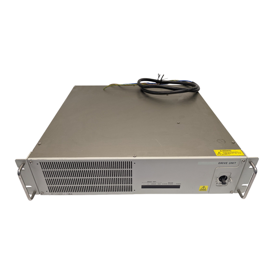
- Page 38 D rive Unit serial number - Identifying proper unit: 2 2 B Drive Unit’s serial number is indicated on the label as shown below. (The following photo is the six-axis Drive Unit.) :RC520DU6 MODEL DRIVE UNIT :00006 SERIAL NO. RC520 Safety and Installation Rev.2...
-
Page 39: Connecting Manipulator And Controller
2. Installation 2.6 Connection to EMERGENCY Connector (Controller) Connect a safeguard switch or Emergency Stop switch to the RC520 EMERGENCY connector for safety. When nothing is connected to the EMERGENCY connector, RC520 does not operate normally. Connector Pin : Before connecting the connector, make sure that the pins are not bent. - Page 40 The Safety Door must be designed and installed so that it does not close accidentally. L atch Release Switch 2 5 B The controller software latches the following conditions: - The safety door is open. - The operation mode is for teaching. RC520 Safety and Installation Rev.2...
- Page 41 In order to change the latched condition of the operation mode for teaching, turn the mode selector switch on the operation unit to the mode for normal or turn the ATTEND (TEACH) control device enable/disable switch to “disable”. Then, close the latch release input. RC520 Safety and Installation Rev.2...
- Page 42 Emergency Stop output terminals. The relay contacts at the EMERGENCY connector (#5 & #6) (normally closed) will open at the input of Emergency Stop state. RC520 Safety and Installation Rev.2...
- Page 43 Make sure that “Emergency Stop” is displayed on the status bar on the monitor window. Release the E. STOP box switch. Execute the RESET command. Make sure that “E-STOP” LEDs are turned OFF and the “Emergency Stop” is no longer visible (or dimmed) from the status bar. RC520 Safety and Installation Rev.2...
- Page 44 *3 The signal from the Emergency Stop switch is designed to use two redundant circuits. An error occurs if the statuses of the two redundant circuits are different for two or more seconds. They must be connected to the same switch with two sets of contacts. RC520 Safety and Installation Rev.2...
- Page 45 Latch Release rated input current 10mA/24V input Emergency Stop output relay contact +30V 0.5A or under 5-6 pin rated load NOTE The total electrical resistance of the Emergency Stop switches and their circuit should be 1 Ω or less. RC520 Safety and Installation Rev.2...
- Page 46 *1: The part indicated with a broken line shows +24V GND Close: latch off the circuit for the four-axis Drive Unit. Open: latch on For the six-axis Drive Unit, there are six motor driver modules in the circuit. RC520 Safety and Installation Rev.2...
- Page 47 *2: The part indicated with a broken line shows +24V Close: latch off the circuit for the four-axis Drive Unit. Open: latch on For the six-axis Drive Unit, there are six motor drive modules in the circuit. RC520 Safety and Installation Rev.2...
- Page 48 Rated electric current consumption of the coil: 1A or under Minimum applicable load: 10mA or under External +24V GND External +24V External +24V GND Drive Unit 2 External +24V GND Drive Unit 3 External +24V GND RC520 Safety and Installation Rev.2...
-
Page 49: Connecting Manipulator And Controller
Connect the Control Unit, the Drive Unit and the Manipulator correctly. Improper connections between the Drive Unit and the Manipulator and between the Control Unit and the Drive Unit may cause improper function of the robot system and also safety problems. RC520 Safety and Installation Rev.2... - Page 50 : Connect the power cable connection and the signal cable connector to the Manipulator immediately after the Manipulator installation. Manipulator without connecting them may result in electric shock and/or malfunction of the robot system as it cannot ensure IP65. RC520 Safety and Installation Rev.2...
- Page 51 Drive Unit on your left hand side facing the Drive Unit. The Manipulator’s serial number is indicated on the signature label of the Manipulator. (The following photo is the six-axis Drive Unit.) MANIPULATOR PS3-AS00 00002 Serial number Model RC520 Safety and Installation Rev.2...
- Page 52 2. Installation P S series and RC520 Connection 3 6 B M/C Power Cable M/C Signal Cable E 2 series and RC520 Connection 3 7 B M/C Power Cable M/C Signal Cable RC520 Safety and Installation Rev.2...
-
Page 53: Power-On
Check the EMERGENCY connector connection. OPTIONAL DEVICE Connect the Dummy Plug or OP500RC to the connector. Connect the AC power cable to the power supply socket. Turn ON both the Drive Unit and Control Unit. RC520 Safety and Installation Rev.2... - Page 54 Controller. When an error appears, check the connection in step (1) to (5) to turn ON the power again. If an error appears after checking the connection contact the supplier. RC520 Safety and Installation Rev.2...
-
Page 55: First Step
<Next> button. (If you select the option to disagree, the Windows setup will be canceled.) After agreeing to the “License Agreement”, the setup starts automatically. (3) Windows Startup Windows reboot automatically after finishing the setup and will be able to use the Controller. RC520 Safety and Installation Rev.2... -
Page 56: Installing Epson Rc+ Software
EPSON RC+ is installed at the factory before shipment with the specified configuration. However, if you need to add an option, upgrade, or re-install, refer to the section Installing EPSON RC+ Software in Appendix A for instructions on installing EPSON RC+. -
Page 57: Writing Your First Program
3. First Step 3.3 Writing your first program Follow these instructions to create a simple application program so that you will become more familiar with the EPSON RC+ development environment. 1. Start EPSON RC+ Double-click the EPSON RC+ icon on the desktop. - Page 58 Leave the jog screen by pressing the Close button located in the lower right corner of the screen. You will see a message saying that changes have been made. Click Yes to save the changes. RC520 Safety and Installation Rev.2...
- Page 59 The robot should jump to each of the points you taught at 20% speed, acceleration, and deceleration. The Power High statement enables your program to run the robot at high (normal) power, which in turn allows the robot speed and acceleration to be increased. RC520 Safety and Installation Rev.2...
- Page 60 Even though this is only a sample project, we will backup the project and system configuration on floppy disk. This is easy to do with EPSON RC+. It is important that you keep regular backups of your applications on external media such as floppy disks.
-
Page 61: Second Step
ROBOT CONTROLLER RC520 manual Setup & Operation 6. I/O Connector Setup & Operation 7 Expansion I/O Board (Option) Fieldbus I/O (Option) EPSON RC+ Option Fieldbus I/O manual Ethernet I/O (Option) EPSON RC+ User’s Guide Ethernet Communication ROBOT CONTROLLER RC520 manual Setup &... -
Page 62: Connection And Display Language4 Of Op Tion Op500Rc
4.2 Connection and Display Language of Option OP500RC Connection ROBOT CONTROLLER RC520 manual Setup & Operation 4. OPTIONAL DEVICE connector EPSON RC+ Option OP500RC manual 1.6. Installation Changing Display Language EPSON RC+ Option OP500RC manual 1.9 Setting Language RC520 Safety and Installation Rev.2... -
Page 63: Third Step
Descriptions of manual contents are indicated in this section. Manuals are supplied by Acrobat PDF to use the Robot system. Select EPSON RC+-[Help]-[PDF Manual] to view the PDF manuals from a PC. (Click <Start>-[Program]-[EPSON RC+] from the Windows desktop.) Software EPSON RC+ User’s Guide... - Page 64 5. Third Step Controller ROBOT CONTROLLER RC520 This manual indicates descriptions of the Robot Controller RC520 and Robot system. - Safety - Specification, Installation, Operation, and Setup - Backup and Restore - Maintenance - Verifying Robot System Operation - Error Codes etc.