
Related Manuals for Honeywell CN100


Summary of Contents for Honeywell CN100
- Page 1 XPERION ELEASE CN100 Controller Hardware Planning and Installation Guide EPDOC-X630-en-516A August 2020...
- Page 2 In no event is Honeywell liable to anyone for any direct, special, or consequential damages. The information and specifications in this document are subject to change without notice.
-
Page 3: Table Of Contents
Contents CONTENTS Contents Chapter 1 - About this guide Chapter 2 - Overview Chapter 3 - Hardware Components Redundant Controller Chapter 4 - CN100 Platform Installation Environmental Specifications Power Considerations Power Requirements Power Consumption Installation Declarations Dimensions and Layouts Dimensions of Redundant CN100 Controller... - Page 4 Contents Removal and Insertion Under Power (RIUP) Replacing a CN100 Controller Replacing a NAM Replacing an IOTA Spare parts and model numbers Chapter 6 - Diagnostics and Troubleshooting LED Indicators of a Redundant Controller Additional Information Chapter 7 - Special Condition of Use and Approved Standards...
-
Page 5: Chapter 1 - About This Guide
August 2020 Initial release of document Introduction to Experion Technology Item Description CN100 CN100 controllers running the eCLR (IEC 61131-3) execution Module environment with CN100 software options configured with Control Builder. Network Network Adaptor Modules (CC-INAM01) provides for Uplink Adapter Ethernet connections and supports copper or Fiber connectivity. - Page 6 Chapter 1 - About this guide How to use this guide The following table outlines the tasks involved in planning and installing a CN100 Controller. The links provided will navigate you through those tasks. Task Go to Check the model number of the See "Hardware Components"...
-
Page 7: Chapter 2 - Overview
CN100 controller is a modular, powerful, and scalable system capable of all remote automation and control applications. When combined with Experion PKS and its simplified SCADA configuration, it solves ® the remote automation requirements. Starting with R515, a new redundant controller CN100 is added in Experion PKS. - Page 8 Chapter 2 - Overview...
-
Page 9: Chapter 3 - Hardware Components
Modules or connect with Series C IOM by IOLINK. Depending on software support, other form factor I/O modules along with Wireless I/O are supported. See the images and table below for the CN100 Platform Hardware. Figure 3-1: Redundant CN100 Controller (CCA) Front View... - Page 10 Chapter 3 - Hardware Components Figure 3-2: Redundant CN100 Controller (DINRAIL) Front View Table 3-1: CN100 Hardware Components Item Model Number Description CC-IION01 I/O NETWORKING & CONTROL MODULE CC-TION11 I/O NETWORKING & CONTROL IOTA CC-TION13 I/O NETWORKING & CONTROL IOTA - DIN RAIL...
- Page 11 Chapter 3 - Hardware Components Item Model Number Description 50154761 SPF - Single mode 20Km 50154762 SPF - Multi mode 2Km...
-
Page 12: Redundant Controller
IOTA. CN100 Controller A device that contains most of the electronics required to perform the function of a process controller. A CN100 module plugs onto an IOTA designed for the CN100. Input Output Termination Assembly (IOTA) An IOTA holds CN100 module, NAM and connection for IO link and RS485. - Page 13 Chapter 3 - Hardware Components Figure 3-3: Redundant Controller (CCA) Figure 3-4: Redundant Controller (DINRAIL)
- Page 14 Chapter 3 - Hardware Components Table 3-2: CN100 Controller Parts Item Description 18-30 VDC power supply (two) RS485 Ports (one) IO Link Port (one) Ethernet Ports on the NAM (2). Fiber ports on the NAM (2). Screw hole: used for locking controller IOTA.
- Page 15 Chapter 3 - Hardware Components Refer to the following table for the specifications. Table 3-3: Redundant Controller Specification Item Specification Processor Dual Core ARM® Cortex™-A9 Core (32 bit) 667 MHz Dynamic 256 Megabytes memory (RAM) Program 128 Megabytes memory (Flash) Nonvolatile 4 Mbits memory...
- Page 16 Chapter 3 - Hardware Components...
-
Page 17: Chapter 4 - Cn100 Platform Installation
CHAPTER CN100 PLATFORM INSTALLATION In this section: Environmental Specifications Power Considerations Installation Declarations Dimensions and Layouts Mounting Wiring and Cabling Planning Connecting with Wireless I/O... -
Page 18: Environmental Specifications
Chapter 4 - CN100 Platform Installation Environmental Specifications The operating conditions are as follows: Storage temperature: -40°C to +85°C (–40°F to +185°F) Operational Ambient temperature (T4): -40°C to +70°C (-40°F to +158°F) Relative humidity: 5% to 95% (non-condensing) Vibration (sinusoidal): excitation: sine-shaped with sliding freq. -
Page 19: Power Consumption
Chapter 4 - CN100 Platform Installation Power Consumption This sections describes the power consumption details of the CN100 NAM. The following table only includes power consumption data of the listed modules and does not include power consumption of any connected instruments. -
Page 20: Dimensions And Layouts
Chapter 4 - CN100 Platform Installation ATTENTION: ESD HAZARD Electrostatic discharge can damage integrated circuits or semiconductors if you touch connector pins or tracks on a printed wiring board. Touch a grounded object to eliminate static electricity Wear an approved anti-static wrist strap... -
Page 21: Dimensions Of Redundant Cn100 Controller
Chapter 4 - CN100 Platform Installation Dimensions of Redundant CN100 Controller The following picture illustrates the physical dimensions of CN100 redundant controllers. Figure 4-1: Redundant CN100 Controller Dimensions (CCA) Figure 4-2: Redundant CN100 Controller Dimensions (DINRAIL) - Page 22 Chapter 4 - CN100 Platform Installation Table 4-3: The Redundant Controller Dimensions Item Dimension (mm) 36.85 168.88 183.97 132.08 140.51 77.54...
-
Page 23: Installation Dimensions For A Redundant Controller
Chapter 4 - CN100 Platform Installation Installation Dimensions for a Redundant Controller The following figure illustrates the layout when one redundant controller is connected with one right end plate. Figure 4-3: The Dimensions for a Redundant Controller Table 4-4: The Layout Dimension... -
Page 24: Mounting
Mount the CN100 Controller IOTA onto the DIN(TH35-7.5) rail. 2. Insert the DIN rail hook to attach the IOTA to the DIN rail. 3. Insert the CN100 Controller onto IOTA making sure that the Controller matches properly with the IOTA connector. - Page 25 9. Insert the CN100 Controller onto IOTA making sure that the Controller matches properly with the IOTA connector. 10. Secure the CN100 controller to the IOTA with two screws located at each side of the metal cover. 11. Insert the NAM onto IOTA making sure that the NAM matches properly with the IOTA connector.
-
Page 26: Wiring And Cabling Planning
Chapter 4 - CN100 Platform Installation Wiring and Cabling Planning In this section: Power Cabling Grounding and Other Considerations Communication Cabling... -
Page 27: Power Cabling
Power Cabling A CN100 Controller installation requires a 24VDC to power the controller and NAM. The CN100 controller is equipped with an on- board protection system to protect against voltage fluctuations beyond the rated range of 18 to 30 VDC. -
Page 28: Grounding And Other Considerations
Chapter 4 - CN100 Platform Installation Figure 4-4: Redundant Controller Power supply Grounding and Other Considerations Grounding and Shielding CAUTION: CN100 controller must be connected to chassis ground. - Page 29 Chapter 4 - CN100 Platform Installation Connect CN100 Controller to earth ground through power input terminal chassis ground pin (pin 33) as illustrated in the following figure. Figure 4-5: Redundant Controller Grounding Grounding and Shielding recommendations: Use individually shielded twisted pair of cables with full foil shield coverage, to minimize crosstalk within the cable bundle.
-
Page 30: Communication Cabling
Other in-cabinet Ethernet cable parts One of the following yellow-colored (FTEA) cables and one of the following green-colored (FTEB) Ethernet cables are used to connect a Control Firewall IOTA to a CN100 Controller IOTA or to a Series C Modules. Description... - Page 31 ATTENTION: Veuillez-vous assurer que vous êtes dans une zone d’atmosphère non explosive avant d’ajuster le sélecteur. The CN100 controller has 2 Ethernet ports on the NAM and use RJ45 type connectors. See the following figure for the pin assignment: Figure 4-6: Pin Assignment of RJ45...
- Page 32 RX+ (Received Data+) RX - ( Received Data-) RS485 Ports The CN100 controller has one RS485 port to some specific equipment. Each port has five terminals: 485 A+, 485 B-, chassis ground and termination. See the following picture for the RS485 pin assignment.
-
Page 33: Connecting With Wireless I/O
CN100 Controller and its Series C I/O or PM I/O. It is a multi-drop network operating at 750 Kilobits per second (Kbps) for Series C I/O. The CN100 Controller has one pair of I/O Link ports identified as I/O Link 1 (IOL1). Each port is configurable to interface with either I/O Link speed. - Page 34 Chapter 4 - CN100 Platform Installation For detailed and complete information about the Wireless Device Management, refer to the Wireless DeviceManager User’s Guide.
- Page 35 CHAPTER MAINTENANCE In this section: CN100 module, NAM, IOTA Safety considerations - PLAN AHEAD! Removal and Insertion Under Power (RIUP) Replacing a CN100 Controller Replacing a NAM Replacing an IOTA Spare parts and model numbers...
-
Page 36: Chapter 5 - Maintenance
Chapter 5 - Maintenance CN100 module, NAM, IOTA ATTENTION: For a redundant controller, the replacement could be proceed on process. The repair process can be conducted only in a nonhazardous area. We recommend that you proceed with extreme warning whenever replacing any component in a control system. -
Page 37: Removal And Insertion Under Power (Riup)
CAUTION: :Explosion hazard. RIUP is not supported in Division 2/ Zone 2 Hazardous locations. Replacing a CN100 Controller In a system with redundant CN100 controllers, when the primary controller fails, the backup controller takes over. And the original one becomes the secondary NAM. The secondary NAM should be... -
Page 38: Replacing A Nam
Chapter 5 - Maintenance Replacing a secondary CN100 controller To replace a CN100 controller 1. Loosen screws at each side of the module that secures the CN100 to the IOTA 2. Carefully remove the CN100 from the IOTA. The system will proceed without the secondary controller. -
Page 39: Replacing An Iota
Chapter 5 - Maintenance Replacing an IOTA To replace an IOTA on Din rail: 1. On the defective IOTA, loosen screws at each side of the module that secures the NAM to the IOTA. 2. Carefully remove the NAM or IOM from the IOTA. 3. - Page 40 ATTENTION: Veuillez-vous assurer que vous êtes dans une zone d’atmosphère non explosive avant d’ajuster le sélecteur. 12. Connect RS485 cable to the RS485 connector on CN100 IOTA board. 13. Connect IOLink cables to IOTA board, if present. a. Connect gray IOLINK cable to IOL1A and IOL1B for IOLINK 1...
-
Page 41: Spare Parts And Model Numbers
Chapter 5 - Maintenance b. Connect violet IOLINK cable to IOL2A and IOL2B for IOLINK 2 interface of the controller. 14. Install the two-wire twisted pair Battery cable onto the MEMORY HOLD-UP connector on the left side of the IOTA board. 15. - Page 42 Chapter 5 - Maintenance...
-
Page 43: Chapter 6 - Diagnostics And Troubleshooting
Provide external indications that enable operating and maintenance personnel to react appropriately when external actions are required. The following diagnostic indicators are provided for the CN100 Controller: Light Emitting Diodes (LEDs) that assist with troubleshooting activities solely at the controller. LEDs are also useful for verifying indications viewed as screen items. -
Page 44: Led Indicators Of A Redundant Controller
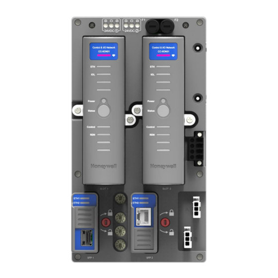
Chapter 6 - Diagnostics and Troubleshooting LED Indicators of a Redundant Controller The following figure shows the LEDs in the redundant Controller. Figure 6-1: CN100 Redundant Controller LED States (CCA) Figure 6-2: CN100 Redundant Controller LED States (DINRAIL) - Page 45 Chapter 6 - Diagnostics and Troubleshooting The various LED states are detailed in the following table.
- Page 46 Chapter 6 - Diagnostics and Troubleshooting Table 6-1: The Controller LED States Condition Color Note Status ETH1 ETH1 (FTEA) link is Good Green Bi-color ETH1 (FTEA) link is Down (FTE A cable disconnected)
- Page 47 IOLink is Down RS485 Supported All power rails on the board are Good Green Single color LED STATUS CN100 is running in primary or non- Solid Green Tri-color redundant role CN100 is running in primary or non- Blinking Green redundant role, soft failure conditions...
-
Page 48: Additional Information
When an CN100 controller failure occurs, you should gather information about the controller and the conditions under which it failed. This information will be beneficial to Honeywell TAC to help in diagnosing and correcting the fault and/or replacing the CN100 controller hardware. - Page 49 1. Hardware revision number of the CN100 controller 2. Firmware revision, both the Boot image and Application image 3. The CN100 System Release number in which the CN100 controller was operating. Additional information which will help the support team to assist you better.
- Page 50 Chapter 6 - Diagnostics and Troubleshooting...
-
Page 51: Chapter 7 - Special Condition Of Use And Approved Standards
CHAPTER SPECIAL CONDITION OF USE AND APPROVED STANDARDS Approval Rating of CN100 Certification Approval Rating Class I, Division 2, Group A,B,C,D; T4 Ex ec IIC T4 Gc Class I, Zone 2 AEx ec IIC T4 Gc AEx nA IIC T4 Gc... -
Page 52: Installation
Chapter 7 - Special Condition of Use and Approved Standards Special Condition of Use for Division 2/Zone 2 Hazardous Location Installation For the United States The installer shall provide transient over-voltage protection external to the apparatus such that the voltage at the supply terminal of the apparatus does not exceed 140% of the voltage rating of the equipment. -
Page 53: For Atex And Iecex
Chapter 7 - Special Condition of Use and Approved Standards For ATEX and IECEx The installer shall provide transient over-voltage protection external to the apparatus such that the voltage at the supply terminal of the apparatus does not exceed 140% of the voltage rating of the equipment. -
Page 54: Canadian Standards
Chapter 7 - Special Condition of Use and Approved Standards Canadian Standards Title Number Nonincendive electrical equipment for use in Class I and II, CAN/CSA-C22.2 Division2 and Class III, Division 1 and 2 hazardous (classified) No. 213 - 17 locations Safety Requirements for Electrical Equipment for Measurement, CAN/CSA-C22.2 Control, and Laboratory Use, Part 1: General Requirements... -
Page 55: Ce Lvd And Emc Compliance Standards
Chapter 7 - Special Condition of Use and Approved Standards CE LVD and EMC Compliance Standards LVD directive Title Number Safety requirements for electrical equipment for measurement, control, and laboratory use – Part 1: General requirements 61010- EMC directive Title Number Electrical equipment for measurement, control and laboratory EN 61326-1... -
Page 56: Iec Standards (Zone 2)
Chapter 7 - Special Condition of Use and Approved Standards Title Number Electromagnetic compatibility (EMC) – Part 4-6: Testing and IEC 61000-4-6 measurement techniques – Immunity to conducted disturbances, induced by radio-frequency fields Electromagnetic compatibility (EMC) – Part 4-8: Testing and IEC 61000-4-8 measurement techniques –... -
Page 57: Notices
Documentation feedback You can find the most up-to-date documents on the Honeywell Process Solutions support website at: http://www.honeywellprocess.com/support If you have comments about Honeywell Process Solutions documentation, send your feedback to: hpsdocs@honeywell.com... - Page 58 Customer Contact Center (CCC). To find your local CCC visit the website, https://www.honeywellprocess.com/en-US/contact- us/customer-support-contacts/Pages/default.aspx. Training classes Honeywell holds technical training classes that are taught by process control systems experts. For more information about these classes, contact your Honeywell representative, or see http://www.automationcollege.com.