Advertisement
Quick Links
Advertisement

Related Manuals for Bosch AMC2 4W-EXT


Summary of Contents for Bosch AMC2 4W-EXT
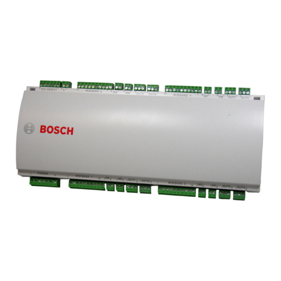
- Page 1 AMC2 4W-EXT API-AMC2-4WE Installation manual...
-
Page 2: System Overview
If an external power supply is used then this should be an PBC-60 (F.01U.026.573) with integrated uninterruptable power supply (UPS). System Overview The AMC2 4W-EXT is connected between the access controller AMC2 4W and the various peripheral devices. Figure 3.4 System overview Host... - Page 3 – the necessary number of AMC enclosures The using of AMC2 4W-EXT modules has no influence on the limit of the maximum of controllers in one system, because it is an extension to an AMC2 4W and not a controller.
-
Page 4: Technical Data
AMC2 4W-EXT Technical Data | en Technical Data – Four Wiegand interfaces for up to four card readers (Output rating: 280 mA) – relay outputs – maximum ratings: switching voltage: 30 Vdc switching current: 1,25 A – operating ratings: 1,25 A @ 30 Vdc... - Page 5 | Technical Data AMC2 4W-EXT Humidity Up to 95%, without condensation Housing material ABS with OC (UL 94 V-0) Dimensions (W/H/D) 232mm x 90mm x 46mm (8.9 x 3.5 x 1.8 in.) Weight app. 0,4 kg (0.88 pounds) WARNING! The voltage drop from the power supply to the AMC has effect on the AMC interfaces.
- Page 6 AMC2 4W-EXT Installing | en Installing NOTICE! To build an UL approved system refer the documentation contained in the folder titled "_UL" on the delivered CD. Mounting The AMC2 can be attached on a standard 35 mm (1.377 in.) mounting rail using a snap-in mechanism. Attach the AMC2 into...
- Page 7 | Installing AMC2 4W-EXT Unmounting NOTICE! To remove the AMC2 from a mounting rail, first, remove all pluggable connectors. Push down the AMC2 until the lower edge snaps out of the mounting rail [1]. Pull the lower end of the AMC2 from the mounting rail [2].
- Page 8 AMC2 4W-EXT Installing | en WARNING! Please note the following specifications. To prevent damage to the relays please remember: – the maximum switching current is 1.25 A – the maximum switching voltage is 30 Vdc – only ohm resistive load can be connected to the relay –...
- Page 9 Risk of Damage! Do not connect externally powered devices in wet mode. This can damage the AMC2 4W-EXT. Each relay output has a separate jumper setting on the underside of the circuit board to select wet (D 2) or dry (D 1) mode.
-
Page 10: Connecting Analog Input Devices
Installing | en 5.11 Connecting Analog Input Devices The AMC2 4W-EXT has eight analog inputs, for example, for potential-free lock mechanisms, or to detect whether a lock is closed or open. The inputs will be connected to the 2-pin pluggable screw connectors: S3, S4, S8, S9, S15, S16, S20, and S21 - refer to Table 7.3. - Page 11 | Installing AMC2 4W-EXT 1. Door open: R 2. Door closed: R = ∞ 3. Open wire: R 4. Short circuit: R The resistor values can vary and depend on the used lock system. The extension package includes 2,2 kΩ resistors which can be used to replace RS and RP resistor.
-
Page 12: Tamper Protection
AMC2 4W-EXT Installing | en 5.12 Tamper Protection To protect the AMC2 against unauthorized access and so prevent tampering with sensitive data, the AMC2 provides an additional interface to connect external tamper contacts. This interface is a potential-free 2-pin pluggable screw connector marked with T. - Page 13 AMC2 4W-EXT Operating Status Display of the AMC2 4W-EXT Because the AMC2 4W-EXT has no display of its own, the AMC2 4W displays status information about the input and output settings of the AMC2 4W-EXT. The selected display mode remains set until the next time the button is pressed.
- Page 14 AMC2 4W-EXT Operating | en Push Display (Example) Description G 192.168.10.255 IP-address of the gateway (Version V 00.44 or higher) M 255.255.255.0 Subnetmask (Version V 00.44 or higher) H 192.168.10.10 IP-address of the host computer DHCP 1 DHCP-status: 1 = on 0 = off D 192.168.10.1...
- Page 15 | Appendix AMC2 4W-EXT Appendix Figure 7.1 Connector blocks of the AMC2 4W-EXT | V 2.6 | 2008.12 Installation manual Bosch Sicherheitssysteme GmbH...
- Page 16 AMC2 4W-EXT Appendix | en Power supply, DC positive (10V - 30V) Shield Power supply (0V) UPS (power good signal) - AC UPS (power good signal) - Battery UPS (power good signal) - DC UPS (power good signal) - Common Table 7.1 Power supply...
- Page 17 | Appendix AMC2 4W-EXT Power supply for external devices - 12V Power supply for external devices - 0V Shield Data RxTx+ Data RxTx- Ground (PAG) Table 7.5 Extension interface Tamper Contact, in Tamper Contact, out Table 7.6 External tamper contact | V 2.6 | 2008.12...
- Page 18 AMC2 4W-EXT Appendix | en Bosch Sicherheitssysteme GmbH Installation manual | V 2.6 | 2008.12...
- Page 19 | Index AMC2 4W-EXT Index cabling 22 contact 6 extension interface 16 inputs 12 interfaces extension 16 reader 12 mounting 18 opening 20 outputs 12 power supply 22 reader interfaces 12 Wiegand 30 resistor 38 Safety notes 9 tamper 40 unmounting 19 V 2.6 | 2008.12...
- Page 24 Bosch Sicherheitssysteme GmbH Robert-Koch-Straße 100 D-85521 Ottobrunn Germany Telefon +49 89 6290-0 +49 89 6290-1020 www.boschsecurity.com © Bosch Sicherheitssysteme GmbH, 2008...