HIKVISION Ultra Series Quick Start Manual
Network box camera
Hide thumbs
Also See for Ultra Series:
- User manual (135 pages) ,
- Quick start manual (2 pages) ,
- User manual (126 pages)
Table of Contents
Advertisement
Quick Links
Advertisement
Table of Contents

Related Manuals for HIKVISION Ultra Series


Summary of Contents for HIKVISION Ultra Series
- Page 1 Network Box Camera Quick Start Guide...
- Page 2 Network Box Camera·Quick Start Guide Quick Start Guide © 2020 Hangzhou Hikvision Digital Technology Co., Ltd. All rights reserved. About this Manual The Manual includes instructions for using and managing the Product. Pictures, charts, images and all other information hereinafter are for description and explanation only. The information contained in the Manual is subject to change, without notice, due to firmware updates or other reasons.
- Page 3 BREACH OF CONTRACT, TORT (INCLUDING NEGLIGENCE), PRODUCT LIABILITY, OR OTHERWISE, IN CONNECTION WITH THE USE OF THE PRODUCT, EVEN IF HIKVISION HAS BEEN ADVISED OF THE POSSIBILITY OF SUCH DAMAGES OR LOSS. YOU ACKNOWLEDGE THAT THE NATURE OF INTERNET PROVIDES FOR...
- Page 4 Network Box Camera·Quick Start Guide NUCLEAR EXPLOSIVE OR UNSAFE NUCLEAR FUEL-CYCLE, OR IN SUPPORT OF HUMAN RIGHTS ABUSES. IN THE EVENT OF ANY CONFLICTS BETWEEN THIS MANUAL AND THE APPLICABLE LAW, THE LATER PREVAILS. Regulatory Information FCC Information Please take attention that changes or modification not expressly approved by the party responsible for compliance could void the user's authority to operate the equipment.
- Page 5 Network Box Camera·Quick Start Guide FCC Conditions This device complies with part 15 of the FCC Rules. Operation is subject to the following two conditions: 1. This device may not cause harmful interference. 2. This device must accept any interference received, including interference that may cause undesired operation.
- Page 6 Network Box Camera·Quick Start Guide supplier or to a designated collection point. For more information see: www.recyclethis.info. Industry Canada ICES-003 Compliance This device meets the CAN ICES-3 (B)/NMB-3(B) standards requirements. Safety Instruction These instructions are intended to ensure that user can use the product correctly to avoid danger or property loss.
- Page 7 Network Box Camera·Quick Start Guide ● In the use of the product, you must be in strict compliance with the electrical safety regulations of the nation and region. Please refer to technical specifications for detailed information. ● The power source should meet limited power source or PS2 requirements according to IEC 60950-1 or IEC 62368-1 standard.
- Page 8 Network Box Camera·Quick Start Guide applied to the location and about any precautions that shall be taken. ● Make sure the power supply voltage is correct before using the camera. ● Do not drop the camera or subject it to physical shock. ●...
- Page 9 Network Box Camera·Quick Start Guide ● Regular part replacement: a few parts (e.g. electrolytic capacitor) of the equipment shall be replaced regularly according to their average enduring time. The average time varies because of differences between operating environment and using history, so regular checking is recommended for all the users.
- Page 10 Network Box Camera·Quick Start Guide ● If the product does not work properly, please contact your dealer or the nearest service center. Never attempt to disassemble the camera yourself. (We shall not assume any responsibility for problems caused by unauthorized repair or maintenance.)
-
Page 11: Table Of Contents
Network Box Camera·Quick Start Guide Table of Contents 1 Appearance Description ............... 11 2 Installation ..................14 2.1 Memory Card Installation ..........14 2.2 Lens Installation ............15 2.3 Camera Mounting ............16 2.3.1 Pendant Mounting ..........17 2.3.2 Wall Mounting ............ 18 2.4 Mounting with Housing .......... -
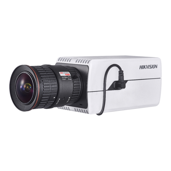
Page 12: Appearance Description
Network Box Camera·Quick Start Guide 1 Appearance Description The overview of the box camera is shown below: Overview Description Description Description Lens mount Auto-iris interface Power indicator ¼-20 UNC screw hole The interfaces on the real panel are described as follows. The actual interfaces may vary with the device model. - Page 13 Network Box Camera·Quick Start Guide Rear Panel Interface Description Item Description Item Description VIDEO Analog video RS-485 D+ or D- connect OUT/CVBS output interface to 485 AUDIO IN Audio input AUDIO Audio output interface interface Alarm input Alarm output ALARM IN ALARM interface, interface,...
- Page 14 Network Box Camera·Quick Start Guide DEBUG Debugging interface Note: Power indicator: red stands for starting and blue for working. To reset the camera default parameters, you need to press and hold the RESET button and power on the camera. After the power on of the camera, you must still press and hold the Reset button for about 10 seconds.
-
Page 15: Installation
Network Box Camera·Quick Start Guide 2 Installation Before you start: ● Make sure the device in the package is in good condition and all the assembly parts are included. ● The standard power supply is 12 VDC or 24 VAC or PoE, please make sure your power supply matches with your camera. -
Page 16: Lens Installation
Network Box Camera·Quick Start Guide (Optional) If you want to unmount the memory card, push to get it ejected. Memory Card Installation Lens Installation The actual device appearance may vary with the model. The following takes a model as an example to illustrate the installation steps. -
Page 17: Camera Mounting
Network Box Camera·Quick Start Guide Lens Installation Steps: Fit the lens (not supplied) to the camera and rotate it to get it tightened. Notes: Install the adapter ring to the lens interface if a C-mount lens is used. A manual-iris lens can be directly installed to the camera without plugging the power cable of the auto-iris to the auto-iris interface. -
Page 18: Pendant Mounting
Network Box Camera·Quick Start Guide 2.3.1 Pendant Mounting Before you start: Pendant mount is not included in package. If you adopt this mounting style, you need to prepare a mounting bracket in advance. The shown pendant mount is for demonstration. Steps: Install the pendant mount to the ceiling with the supplied screws. -
Page 19: Wall Mounting
Network Box Camera·Quick Start Guide Adjust Surveillance Angle Loosen the adjusting knob. Hold the camera body to adjust panning and tilting position. Tighten the knob after adjustment. Adjust zoom and focus level. Refer to Section 2.5. 2.3.2 Wall Mounting Before you start: Wall mount is not included in package. - Page 20 Network Box Camera·Quick Start Guide Separate Pedestal 2. Fix the pedestal to camera body. Fix Pedestal to Camera 3. Install the wall mount to wall. 4. Install the pedestal together with the camera back to wall mount. Install Camera to Wall Mount 5.
-
Page 21: Mounting With Housing
Network Box Camera·Quick Start Guide Adjust Surveillance Angle 6. Adjust zoom and focus level. Refer to Section 2.5. Mounting with Housing Before you start: The shown housing is not included in package. You need to prepare one if you adopt this mounting style. Also, for housing mounting, you need to prepare suitable brackets in advance. - Page 22 Network Box Camera·Quick Start Guide Install Camera to Mounting Plate Screw the mounting plate together with the camera back to the housing. Note: Push the camera as close to the window as possible. Window Cable Outlet Install Camera to Housing Connect and route cables through the cable outlet of the housing.
- Page 23 Network Box Camera·Quick Start Guide For network, alarm input and output, and audio input and output, plug corresponding plugs to the rear panel of the camera. See Figure 1-1. For power supply and RS-485, see the following figure. Heater To camera RS-485 -, yellow RS-485 +, orange To camera...
- Page 24 Network Box Camera·Quick Start Guide Heater To camera RS-485 -, yellow RS-485 +, orange To camera To power source 24 VAC 24 VAC Figure 2-11 Wiring Board in Housing Buckle the housing. Install the housing to surveillance scene. Using brackets, the housing supports wall mounting, pole mounting, and pendant mounting.
- Page 25 Network Box Camera·Quick Start Guide Wall Mount Horizontal Pole Mount Pendant Mount Install the bracket onto the wall/ceiling/pole. The wall mounting bracket, pole mounting bracket, and the pendent bracket are shown in the figures below. Figure 2-12 Install the Bracket to Mounting Place (1) Figure 2-13 Install the Bracket to Mounting Place (2) Fix the housing (with camera) onto the bracket with the supplied screws.
-
Page 26: Mounting Type Ii Housing
Network Box Camera·Quick Start Guide Figure 2-14 Fix the Housing to Brackets (1) Figure 2-15 Fix the Housing to Brackets (2) Adjust zoom and focus. Refer to Section 2.5. 2.4.2 Mounting Type II Housing Steps: Connect and route cables through the cable outlet of the housing. - Page 27 Network Box Camera·Quick Start Guide For network, alarm input and output, and audio input and output, plug corresponding plugs to the rear panel of the camera. See Figure 1-1. For power supply and RS-485, see the following figure. Heater To camera RS-485 -, yellow RS-485 +, orange To camera...
- Page 28 Network Box Camera·Quick Start Guide Wall Mount Horizontal Pole Mount Pendant Mount Column Mount Junction Box Integrated Mount Install the bracket onto the wall/ceiling/pole/ground. The wall mounting bracket, pole mounting bracket, pendent bracket, column mounting bracket, integrated mounting bracket, and junction box are shown in the figures below.
- Page 29 Network Box Camera·Quick Start Guide Integrated Wall Wall Mount Integrated Junction Box Mount Figure 2-17 Install the Bracket to Mounting Place Fix the housing (with camera) onto the bracket with the supplied screws. Loosen the adjusting screw to adjust the surveillance angle of the camera.
- Page 30 Network Box Camera·Quick Start Guide Figure 2-18 Fix the Housing to Brackets (1) Figure 2-19 Fix the Housing to Brackets (2)
-
Page 31: Zoom And Focus Adjustment
Network Box Camera·Quick Start Guide Integrated Mount Adjusting Screw Junction Box Figure 2-20 Fix the Housing to Brackets (3) Column Mount Adjusting Screws Figure 2-21 Fix the Housing to Brackets (4) Adjust zoom and focus. Refer to Section 2.5. Zoom and Focus Adjustment Steps: Power on the camera. - Page 32 Network Box Camera·Quick Start Guide Connect the video out interface of the camera to the installation display device. Adjust zoom and focus. For certain camera models, zoom and focus must be manually adjusted via zoom/focus lever according to the image on the display device.
-
Page 33: Activate And Access Network Camera
Network Box Camera·Quick Start Guide 3 Activate and Access Network Camera Scan the QR code to get Activate and Visit Network Camera. Note that mobile data charges may apply if Wi-Fi is unavailable... - Page 34 UD19325B...