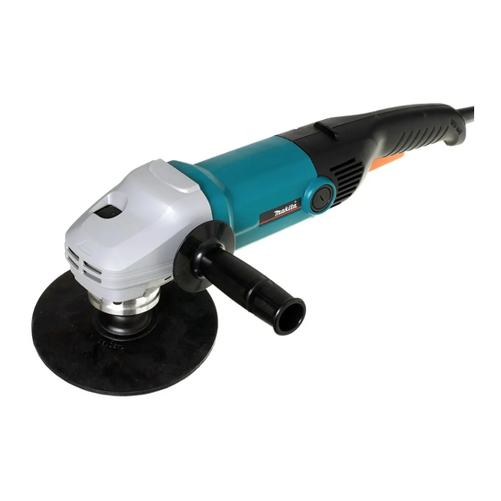
Makita SA7000 Technical Information
Angle sander 180mm
Hide thumbs
Also See for SA7000:
- Instruction manual (45 pages) ,
- Instruction manual (12 pages) ,
- Instruction manual (49 pages)
Advertisement
Quick Links
T
ECHNICAL INFORMATION
Models No.
Description
C
ONCEPT AND MAIN APPLICATIONS
Model SA7000 has been developed as a sister tool of SA7000C,
featuring all the advantages of SA7000C except electronic control.
S
pecification
Voltage (V)
110
120
127
220
230
240
Capacities: mm (")
No load speed: min.
Electronic control
Variable speed control by trigger
Protection against electric shock
Cord length: m (ft)
Net weight: kg (lbs)
S
tandard equipment
Rubber pad 170 ............................................ 1
Sanding lock nut 14-18 ............................... 1
Head cover ................................................... 1
(+) Round head screw M14 ......................... 2
Side grip ....................................................... 1
Lock nut wrench 35 ...................................... 1
Note: The standard equipment for the tool shown may differ from country to country.
O
ptional accessories
Accessories for 180mm (7") angle sander
SA7000
Angle Sander 180mm (7")
Current (A)
Cycle (Hz)
13
50/60
11
50/60
12
50/60
6.7
50/60
6.4
50/60
6.1
50/60
Abrasive disc
Pad
= rpm
-1
Constant speed control
Soft start
Electronic current limiter
Variable speed control by dial
H
W
Length (L)
Width (W)
Height (H)
Continuous Rating (W)
Input
Output
1,400
800
---
800
1,400
800
1,400
850
1,400
850
1,400
850
180 (7)
180 (7)
5,500
No
No
No
No
No
Double insulation
Chile, Brazil: 2.0 (6.6)
Other countries: 2.5 (8.2)
3.3 (7.3)
PRODUCT
P 1/ 6
L
Dimensions: mm (")
453 (17-7/8)
170 (6-11/16)
136 (5-3/8)
Max. Output (W)
1,700
1,700
1,700
1,900
1,900
1,900
Advertisement

Related Manuals for Makita SA7000


Summary of Contents for Makita SA7000
- Page 1 Models No. SA7000 Description Angle Sander 180mm (7") ONCEPT AND MAIN APPLICATIONS Model SA7000 has been developed as a sister tool of SA7000C, featuring all the advantages of SA7000C except electronic control. Dimensions: mm (") Length (L) 453 (17-7/8) Width (W)
-
Page 2: Necessary Repairing Tools
Center attachment for 1R045 Removing Gear housing cover and Bearing box [2] Lubrication Fig. 1 Put 40g of Makita grease SG. No.0 into the gear room of Gear housing for a long gear life. (Fig. 1) Gear room [3] Disassembling and Assembling [3]-1. - Page 3 Note: Disassembling can be done without disassembling Gear housing section. 1) Remove Sanding pad. 2) Using a Makita impact driver and 1R229, remove four M5x16 Hex socket head bolts that fasten Bearing box to Gear housing. 3) Insert two slotted screwdrivers into the two slits in diagonal opposite positions between Bearing box and Gear housing.
- Page 4 P 4/ 6 epair [3]- 2. Replacing Spiral Bevel Gear 43 and Ball Bearing 6202DDW (cont.) DISASSEMBLING 3) Remove Ball bearing 608LLB from spindle using 1R269 as illustrated to left in Fig. 8. 4) Remove Retaining ring S-15 from Spindle using 1R291 as illustrated to right in Fig. 8. Now Spiral bevel gear 43 and Woodruff key can be removed from Spindle by hand.
-
Page 5: Circuit Diagram
P 5/ 6 ircuit diagram Fig. D-1 Color index of lead wires' sheath Black White Insulated connector Field Insulated connector Noise Black or brown suppressor* [Name plate side] Switch *Noise suppressor is not used Blue or white for some countries. iring diagram [1] Wiring on Motor Housing Motor housing... - Page 6 P 6 / 6 iring diagram [2] Wiring in Handle Fig. D-3 Before setting Switch in place, fix Lead wires with Lead wire holders under switch as illustrated below. Lead wires (white) of Noise suppressor* Field lead wire (red) Field lead wire (white) Route two Field lead wires (red, white) *If Noise suppressor is used between the rib and the boss and between...