Advertisement
Quick Links
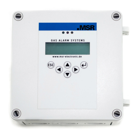
PolyGard
2 Multi-Gas-Controller MGC2-K
Quick Start Guide
Please read this Quick Start Guide completely before installing the PolyGard®2
Multi-Gas Controller MGC2-K. It contains important information for your safety and
correct operation of the PolyGard®2 Multi-Gas Controller MGC2-K.
Visit
http://www.honeywellanalytics.com
for the PolyGard®2 MGC2-K Multi-Gas
Controller manual with full instructions for download.
1
Intended Use
The PolyGard
2 MGC2-K is designed for detection and warning detection of toxic, combustible or dangerous
atmosphere in many commercial and industrial applications.
The intended sites are all areas being directly connected to the public low voltage supply, e.g. residential,
commercial and industrial ranges as well as small enterprises (according to EN50 082).
The PolyGard
2 Multi Gas Controller MGC2 must not be used in potentially explosive atmospheres. The sensor
must only be employed in areas within the environmental conditions specified in the Technical Data.
2
Functional Description
2.1.
General
The Multi-Gas-Controller is designed for the connection of max. three analog sensors with 4-20 mA signal and
eight Honeywell sensors.
The controller monitors the measured values and activates the alarm relays if the set local alarm thresholds for pre-
alarm and main alert have been exceeded or if there are the alarm messages coming from the eight digital sensors
via RS-485 communication.
The SIL 2 compliant self-monitoring function in the MGC2 activates the fault message in case of an internal error
as well as in case of a fault at the 4-20 mA input / output current signals or if there is a communication error to the
digital sensors.
Other options such as three-color status LED, warning buzzer, digital input for acknowledgment or test function
ensure proper adaptation to the wide range of applications in gas detection technology.
3
Installation
Electronics can be destroyed by electrostatic discharge (ESD). Therefore, the installation
work should be done only by persons connected to ground, e. g. with a wrist strap
connected to ground or by standing on a conductive floor (acc. to DIN EN 100015).
3.1.
Mounting Instructions
When choosing the mounting site please pay attention to the following:
•
Choose mounting location of the sensor according to the local regulations.
•
Mount the sensor at a location with minimum vibration and minimum variation in temperature (avoid
direct sunlight).
•
Avoid locations where water, oil etc. may influence proper operation and where mechanical
damage might be possible.
•
Provide adequate space around the sensor for maintenance and calibration work.
•
Observe possible local instructions.
3.2.
Installation Work
Assembly work must only be carried out under gas-free conditions.
Do not drill holes in the housing. Use only the providing know-outs.
•
Open housing cover.
•
Break out the required pre-embossed knockouts on the housing for cable glands and Sensor
Cartridge.
•
Cables are introduced from above.
•
The MGC2 Controller is fixed to the wall through the four marked mounting points at the back side
of the housing. These mounting points are accessible after opening the housing. See figure below.
•
The dimensions XX depend on the type and can be read on the back of the housing, it is115 mm.
•
The mounting points are covered by closing the cover at the end of the assembly.
•
Close the cover.
XX
Installation of Controller:
4
Electrical Connection
Assembly work must only be carried out under gas-free conditions!
Consider static electricity instructions (ESD)!
4.1.
Wiring
•
The technical requirements and regulations for wiring, electrical safety, as well as project specific and
environmental and local conditions etc. must be observed when mounting.
•
We recommend the following cable types1:
Europa
Power Supply 230 V
NYM-J 3 x 1,5 mm
Alarm message 230 V (also possible together with power supply.)
NYM-J X x 1,5 mm
Signal message, bus connection, warning devices 24 V
J-Y(St)Y 2x2 x 0,8 mm
Possibly connected external analog transmitters
J-Y(St)Y 2x2 x 0,8 mm
1
The recommendation does not consider local conditions such as fire protection etc.
•
Use copper conductors only for the terminal is only for connection to copper wire.
•
Avoid any influence of external interferences by using shielded cables for the bus line, but do not connect
the shield.
•
Remove the cable isolation as short as possible. It is important to ensure that bare wires, e.g. wire shields
do not come into contact with the mounted PCB (risk of short-circuit).
•
Low voltage wire and mains connected wire must be fixed separately by cable ties or similar, to secure
against looseness.
•
Analog sensors are connected directly to the spring type terminals of the module. The correct polarity
must be observed.
•
The alarm signals are available as potential-free change-over contacts. If required, the voltage supply is
available at the terminal L.
The exact position of the terminals for the sensors and alarm relays is shown in the connection diagrams.
4.2.
Wiring Diagrams
Wiring Diagram, Example
Relay drawn de-energized
Power Supply
Relays Mode = Energized (Alarm ON = Relay OFF)
24 VDC
Relay
Relay
Alarm 1
Alarm 2
X1
3
2
1
X2
3
2
1
X3
3
2
1
Multi Gas Controller MGC2 24 VDC
Digital
Field Bus
Analog
Analog
Digital
Input
Output
Input
Output
1 2 3
1
2
3
4
1
2
3
4 5 6 7
1
2
3
1
2
3
5
Operation
The complete configuration and service are made via operating keys in combination with the LCD display screen. Security
is provided via four password levels against unauthorized intervention
Operation is done via 6 buttons
5.1.
Function of the Keys and LEDs on the Keypad
Exits programming, returns to the previous menu level.
Enters sub menus, saves parameter settings.
Scrolls up & down within a menu, changes a value.
Changes cursor position.
USA / Canada
The status LEDs indicate the operating state.
2
14 AWG / 300 V
2
14 AWG / 300 V
Green:
Continuous:
2
min. 300 V
Flashing:
2
min. 300 V
Yellow:
Continuous:
Slowly flashing: = Warming up
Fast flashing:
Red:
The backlight of the display changes from green to red when an alarm is active.
5.2.
Code Levels
All inputs and changes are protected by a four-digit numeric code (= password) against
unauthorized intervention according to the regulations of all national and international
standards for gas warning systems. The menu windows of status messages and
measuring values are visible without entering a code.
The access to a code level is cancelled if no button is pushed within 15 minutes or if there
is no data communication between display and basic board.
The code levels are classified in order of priority: Priority 1 has top priority.
Priority 1: (code not changeable)
Code level priority 1 is intended for the service technician of the installer to change
parameters and set-points. This password allows working on all settings. For opening the
parameter menus, you must first activate the service mode after code release.
Relay
Relay Voltage
Fault
Max. 230
Priority 2: (code not changeable)
This functionality isn't available.
X4
3
2
1
Priority 3: (customer password is settable)
Customer password is inactive in delivery state and is activated by entering a value. Same
behavior as priority 1 password, only changing the customer password is not possible.
Normally the code is only known by the service technician who has last changed it since
it can be changed individually via priority 1.
Priority 4: (password 1234) (code not changeable)
Code level priority 4 allows the operator after activation of the operation mode "Service
Mode" to read all parameters as well as all test functions of the alarm relays, analog
outputs and LCD.
- Manual test function of the alarm relays (functional test of the connected actuators),
- Manual test function of the analog outputs (functional test of the connected actuators),
1
2
3
- Manual test function of the LCD (functional test of the LCD display and the LEDs).
5.3.
Customer Password
Storage of an individual customer password on the display for changing the parameters.
See 5.2 Code level Priority 3. Changing the password only via access of the code level
1.
= Normal operation
= Maintenance message
= Failure
= Special mode
= Alarm
Advertisement

Related Manuals for Honeywell MSR Electronic PolyGard 2 MGC2-K


Summary of Contents for Honeywell MSR Electronic PolyGard 2 MGC2-K
- Page 1 The Multi-Gas-Controller is designed for the connection of max. three analog sensors with 4-20 mA signal and Priority 1: (code not changeable) eight Honeywell sensors. Wiring Diagram, Example The controller monitors the measured values and activates the alarm relays if the set local alarm thresholds for pre-...
- Page 2 LCD-Display Technical Data MGC2 Two lines, 16 characters each, background highlighted in two colours Electrical Operation Menu driven via six push-buttons Power supply 24 V DC ± 20 %, reverse-polarity protected Power consumption 5 V, 60 mA, 0,3 VA 24 V AC ± 15 % Overvoltage category Power consumption (24 V DC) Control Board...