
Related Manuals for HIKVISION CSR-I Series


Summary of Contents for HIKVISION CSR-I Series
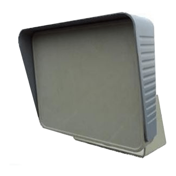
- Page 1 CSR﹣IN(P) Single Lane High- Precision Positioning and Speed Measurement Radar User Manual...
-
Page 2: Table Of Contents
Contents Chapter 1 Product overview ..........................1 Product introduction ..........................1 2. Technical Specification ..........................1 3. Electrical interface............................2 a. Power supply interface ..........................2 b. Communication interface ..........................2 Chapter 2 Installation and Usage of Product ....................3 Common installation methods ......................... -
Page 3: Chapter 1 Product Overview
Chapter 1 Product overview 1. Product introduction The panel microwave speed measurement radar is implemented on Doppler principle, and it is also called Doppler radar. The working principle is that the radar emits a fixed frequency microwave signal towards a target and then receives the reflected signal. There will be a frequency difference between the emission beam and the echo, which is called Doppler frequency shift. -
Page 4: Electrical Interface
Rated voltage:12V DC Rated current: 0.3A 3. Electrical interface Power supply interface Table 1.1 Power Supply Interface Definition of CSR-I Radar Color Illustration Remarks DC12V Positive Terminal of Power Supply Black Radar Earth Attention:There is a requirement of polarity for 12V DC power supply,which cannot be connected inversely。... -
Page 5: Chapter 2 Installation And Usage Of Product
DB9 female Wire color Signal Illustration Remarks A+ Brown Transmission and The positive terminal of receiving and Reception transmitting differential signal B- White Transmission and The negative terminal of receiving and Reception transmitting differential signal Green Radar Earth Signal Earth Table 1.3 Communication Interface Definition of CSR-I Radar Attention: The communication interface should be designated before leaving the factory. - Page 6 Figure 2.1 b. Side loading mode This mode is to install the radar on the roadside or law enforcement vehicles, to measure speed from the side of the target, shown in figure 2.2.It is suitable for static speed measurement, moving speed measurement, vehicle speed prompt cards and so on. Recommendation for the radar model: CSR-IR, CSR-IH, CSR-IX Figure 2.2 c.
-
Page 7: The Steps Of Radar Installation
Before installing the radar, we need to install cardon first. Cardon is one of the most common methods to install the radar of CSR-I series and it is able to be installed in the different environmental conditions after adjusting appropriately. - Page 8 Figure 2.6 b. Adjust the installation position of radar For the top loading mode, install the radar right above the lane and the detection direction of the radar is towards the middle of the lane as shown in the figure 2.7. For other methods, put the radar towards the position expected.
-
Page 9: The Debugging And Usage Of Software
3. The debugging and usage of software a. Software introduction The radar of CSR-I series are all allocated with the debugging software TSRadar2.01. Not only can it set the all the kinds of parameters of the radar in detail, but also control the working conditions of radar very easily. - Page 10 Figure 2.10 2). Serial port Please confirm the connection between radar and the host computer is correct and select the correct serial port first on the surface of TSRadar2.01. As shown in the figure 2.11: Figure 2.11 Attention: If the connection port is chosen incorrectly, the debugging software cannot receive any information.
- Page 11 Figure 2.13 For instance: if the mode of “contact terminal” is needed, click the button of “Enter the setup” first and then choose the contact terminal, and then, click the “work mode” to confirm. Click the “Quit the setup” in the final. 4) Mutual information “...
-
Page 12: Chapter 3 Radar Communication Protocol
Chapter 3 Radar Communication Protocol 1. Overviews he radar outputs FEh FDh FDh FEh after power is on and reset, and then enters the speed measurement state. The default measurement range is between 05h and F0h (corresponding to 5~ 240km/h).The parameters of radar can be set after pressing the “Enter the setup” command, which takes the radar into the configuration state. - Page 13 1, Enter the setup: FAh 31h 30h 30h FBh Stop sending and then reply: FAh 32h xxh 3xh FBh Defining of xx: 30h indicates execute the command correctly, 31h indicates incorrectly. The same as the below. 3xh is flag byte, undefined. 2, Exit the setup: FAh 32h 30h 30h FBh In the setup state, reply: FAh 32h xxh 3xh FBh, then restore the measurement state;...
- Page 14 Defining of x, 0: single byte, no direction and no frame format, it’s default format. 1: Double bytes, with direction and no frame, the first byte means direction--close, F9h; away, F8h; uncertainty, F7h; The radar with no The second byte means the target speed. direction recognition fixed outputs F7h and outputs F7h 00h with no speed in the continuous mode.
- Page 15 Define x as the length of the character string including 00h which is the tail byte of the character string. Eg.: FAh 3dh 30h 6Bh 30h 31h 2dh 76h 32h 2eh 31h 30h 2eh 33h 33h FBh Same as, 14, Inquire the product serial number: FAh 3fh 32h 30h FBh Reply: Ah 32h 31h 30h FBh if there is no product serial number or the product serial umber is illegal.
-
Page 16: Chapter 4 Maintenance And Common Fault Judgment
Chapter 4 Maintenance and common fault judgment The radar is the product applied to domain with high technique and high sensitivity. Please read the direction of the product carefully before using. 1. Please use the high quality DC power supply voltage which could meet the requirements and an independent power supply is needed to prevent crosstalk from other devices. - Page 17 Typical radar abnormal and self-diagnosis methods General troubleshooting methods Failure phenomenon 1、At the moment of electrifying the radar,please check if the serial port is able to receive the bytes FE、FD、FD、FE. If not, please check if the line is connected firmly, if the line sequence is correct, if the upper computer’s serial port is chosen No reaction correctly, if the positive and negative electrode of radar power line is correct(red after...
-
Page 18: Appendix 1 The Correction Calculation Method Of The Target Speed
The correction calculation method of the target Appendix 1 speed The radar measures the radial speed of the moving target relative to the radar. The component speed of the target is in the beam axis of radar between the radiation , where theta is formed direction of the radar and the moving direction of the target. - Page 19 Figure 5.2 Install diagram of the radar for correcting the speed Where ---the speed of the target(km/h) ---the speed output of the radar(km/h) ---the suspension height between the radar and the ground(m) ---the longitudinal distance between the center of the radiation and the vertical pole.(m) ---the distance between the position of the radar and the vertical pole(m) d ---the horizontal distance between the center of the radiation and the...
- Page 20 (5.3) For the far lanes, the correction equation is as follow, (5.4) In (5.3) and (5.4), means the speed of the near lanes(km/h) and means the speed of the far lanes(km/h). The meaning of is shown in figure 5.3. Users can use the above equations for a more accurate speed correction according to the actual trigger position.
-
Page 21: Appendix 2 The Radar Common Parameters Instruction
Appendix 2 The radar common parameters instruction Sensitivity The lower the sensitivity is, the more sensitive the radar is, the more easily taking photos is triggered. The default of sensitivity after leaving the factory is 20, which ranges from 1 to 240. Normally, users do not need to adjust. ...