Table of Contents
Advertisement
Quick Links
Advertisement
Chapters
Table of Contents

Related Manuals for Yamaha CEmarking RCX240


Summary of Contents for Yamaha CEmarking RCX240
- Page 1 RCX240/RCX221/RCX222 YAMAHA ROBOT CONTROLLER marking Supporting Supplement Manual ENGLISH YAMAHA MOTOR CO., LTD. IM Operations 882 Soude, Naka-ku, Hamamatsu, Shizuoka 435-0054.Japan E115-Ver. 1.01 URL http://www.yamaha-motor.jp/robot/index.html...
- Page 3 Introduction Thanks for purchasing the YAMAHA robot controller RCX240/RCX221/RCX222. This manual describes the CE marking for the RCX240/RCX221/RCX222. When shipping the RCX240/RCX221/RCX222 to Europe or when using it in Europe, always read this manual thoroughly to use the controller correctly.
- Page 4 MEMO Introduction...
-
Page 5: Table Of Contents
General contents General contents Introduction Chapter 1 USING THE ROBOT SAFELY 1.1 Safety information 1.2 Particularly important cautions 1.2.1 System design safety points 1.2.2 Installation safety points 1.2.3 Wiring safety points 1.2.4 Start-up and maintenance safety points 1.2.5 Safety precautions during robot operation 1.2.6 Precautions for disposal 1.3 Safety measures for robots 1.3.1 Safety measures for SCARA type robots... - Page 6 Chapter 3 SYSTEM OVERVIEW 3.1 System overview 3.1.1 Main system configuration 3.2 Control system configuration 3.2.1 Basic configuration 3.2.2 Power supply and emergency stop system circuit configuration 3.3 Programming box (RPB-E) 3.3.1 Part names and functions 3.3.2 RPB connector 3.4 SERVICE mode 3-11 3.4.1 What is SERVICE mode? 3-11...
- Page 7 Chapter 6 SPECIFICATIONS 6.1 Controller 6.1.1 Basic specifications 6.1.1.1 RCX240 6.1.1.2 RCX221 6.1.1.3 RCX222 6.1.2 Basic functions 6.1.3 External view 6.1.3.1 RCX240 6.1.3.2 RCX221 6-11 6.1.3.3 RCX221HP 6-12 6.1.3.4 RCX222 6-13 6.1.3.5 RCX222HP 6-14 6.2 Programming box 6-15 6.2.1 Basic specifications 6-15 6.2.1.1 RPB-E 6-15...
- Page 8 MEMO General contents...
- Page 9 Chapter 1 USING THE ROBOT SAFELY Contents 1.1 Safety information 1.2 Particularly important cautions 1.2.1 System design safety points 1.2.2 Installation safety points 1.2.3 Wiring safety points 1.2.4 Start-up and maintenance safety points 1.2.5 Safety precautions during robot operation 1.2.6 Precautions for disposal 1.3 Safety measures for robots 1.3.1 Safety measures for SCARA type robots 1.3.2 Safety measures for single-axis robots, Cartesian...
-
Page 11: Chapter 1 Using The Robot Safely
Explains key points in the operation in a simple and clear manner. Use any of the following approaches to this manual when installing, operating and adjusting the YAMAHA robot and/or controller so that you can quickly refer to this manual when needed. -
Page 12: Particularly Important Cautions
1.2 Particularly important cautions To use YAMAHA robots and controllers safely and correctly, always comply with the safety rules and instructions. Please note, however, this supplementary manual cannot cover all items regarding safety. So it is extremely important that the operator or user have knowledge of safety and make correct decisions regarding safety. -
Page 13: Installation Safety Points
STARTING INSTALLATION OR WIRING WORK. FAILURE TO SHUT OFF ALL PHASES MAY CAUSE ELECTRICAL SHOCK OR PRODUCT DAMAGE. • YAMAHA ROBOTS AND ROBOT CONTROLLERS ARE NOT DESIGNED TO BE EXPLOSION-PROOF. DO NOT USE THEM IN LOCATIONS EXPOSED TO INFLAMMABLE GASES, GASOLINE OR SOLVENT THAT COULD CAUSE EXPLOSION OR FIRE. -
Page 14: Wiring Safety Points
1.2 Particularly important cautions 1.2.3 Wiring safety points WARNING • ALWAYS SHUT OFF ALL PHASES OF THE POWER SUPPLY EXTERNALLY BEFORE STARTING INSTALLATION OR WIRING WORK. FAILURE TO SHUT OFF ALL PHASES MAY CAUSE ELECTRICAL SHOCK OR PRODUCT DAMAGE. CAUTION •... -
Page 15: Start-Up And Maintenance Safety Points
1.2 Particularly important cautions 1.2.4 Start-up and maintenance safety points DANGER • NEVER ENTER THE ROBOT'S WORKING ENVELOPE WHILE THE ROBOT IS OPERATING OR THE MAIN POWER IS TURNED ON. FAILURE TO FOLLOW THIS INSTRUCTION MAY CAUSE SERIOUS ACCIDENTS INVOLVING INJURY OR DEATH. - Page 16 • IF A COMPONENT USED IN THE ROBOT OR CONTROLLER NEEDS TO BE REPLACED OR REPAIRED, ALWAYS FOLLOW THE INSTRUCTIONS FROM YAMAHA. INSPECTION AND MAINTENANCE OF THE CONTROLLER OR ROBOT BY ANY PERSON WHO DOES NOT HAVE THE REQUIRED KNOWLEDGE AND EXPERTISE IS DANGEROUS AND MUST BE AVOIDED.
-
Page 17: Safety Precautions During Robot Operation
1.2 Particularly important cautions CAUTION • When using ferrite cores for noise elimination, fi t them to the power cable as close to the robot controller and/or the robot as possible, to prevent malfunctions due to noise. • Back up the robot controller internal data in an external storage device. The robot controller internal data (programs, point data, etc.) may be lost or deleted for unexpected reasons. -
Page 18: Precautions For Disposal
1.3 Safety measures for robots 1.2.6 Precautions for disposal CAUTION • When disposing of this product discard it as industrial waste. Take appropriate measures in compliance with legal regulations in your country or entrust its proper disposal to a company authorized to handle industrial waste. -
Page 19: Warning Labels And Marks
1.5 Warning labels and marks 1.5 Warning labels and marks 1.5.1 Warning labels The warning labels shown below are affixed to the controller. To use the YAMAHA robot and controller safely and correctly, be sure to observe the instructions and caution on the labels. -
Page 20: Industrial Robot Operating And Maintenance Personnel
1.6 Industrial robot operating and maintenance personnel (3) "High Temperature Hazard" mark Indicates that the area around this mark may become very hot. Heatsinks and regenerative unit become hot during and shortly after operation. Do not touch them to avoid burns. 1.6 Industrial robot operating and maintenance personnel Operators or persons who handle the robot such as for teaching, programming, movement check, inspection, adjustment, and repair must receive appropriate training and also have... - Page 21 Chapter 2 CE MARKING Contents 2.1 CE Marking 2.2 Safety standards 2.2.1 Cautions regarding compliance with EC Directives 2-1 2.2.2 CE marking 2.2.3 Applicable EC Directives and their related standards 2-2 2.2.4 Robots subject to CE Marking 2.2.5 Cautions regarding the official language of EU countries 2-2 2.3 Usage conditions...
-
Page 23: Chapter 2 Ce Marking
EC Directives in cases where the robot is used independently. Customers who incorporate a YAMAHA robot into their final system which will be shipped to, or used, in the EU, should therefore verify that the overall system is compliant with EC Directives. -
Page 24: Applicable Ec Directives And Their Related Standards
: YK-X series, YK-XG series 2.2.5 Cautions regarding the official language of EU countries For YAMAHA robots that will be installed in EU countries, the language used for the user's manuals, CE declarations, and operation screen characters is English only. -
Page 25: Usage Conditions
In order to conform to the EMC Directive, the customer must evaluate the finished product (entire system) and take necessary countermeasures. Refer to EMC countermeasures for single units of YAMAHA robots, which are described in Chapter 4 in this manual. - Page 26 MEMO Chapter 2 CE MARKING...
- Page 27 Chapter 3 SYSTEM OVERVIEW Contents 3.1 System overview 3.1.1 Main system configuration 3.2 Control system configuration 3.2.1 Basic configuration 3.2.2 Power supply and emergency stop system circuit configuration 3.3 Programming box (RPB-E) 3.3.1 Part names and functions 3.3.2 RPB connector 3.4 SERVICE mode 3-11 3.4.1 What is SERVICE mode?
-
Page 29: Chapter 3 System Overview
(1) RCX240 Example: YK500XG only All the axes on the robot controller are used as the main robot axes. System for controlling one robot RPB-E YAMAHA robot External device (PLC etc.) External emergency stop circuit Emergency stop button Safety relay Safety door switch, etc. - Page 30 3.1 System over view (2) RCX221/RCX222 Example: XY-X series System for controlling one robot O P .1 RPB-E O P .2 YAMAHA robot External emergency stop circuit Emergency stop button Safety relay External device Safety door switch, etc. (PLC etc.)
-
Page 31: Control System Configuration
3.2 Control system configuration 3.2 Control system configuration 3.2.1 Basic configuration The basic block diagram of the RCX robot controller system is shown below. (1) RCX240 Basic block diagram DRIVER POWER CN10 MOTOR HEATSINK DRIVER 2 CN12 CN14 ROB I/O XY BATT XY DRIVER 1 ROB I/O ZR... - Page 32 3.2 Control system configuration (2) RCX221 Basic block diagram MOTOR DRIVER2 BOARD ASSY DRIVER2 BOARD ASSY RGEN TEMP ACIN D.POWER BOARD ASSY ROB I/O XY CPU BOARD ASSY SAFETY CN12 SD MEMORY OP.BOARD OP.BOARD Chapter 3 SYSTEM OVERVIEW...
- Page 33 3.2 Control system configuration (3) RCX222 Basic block diagram MOTOR DRIVER2 BOARD ASSY DRIVER2 BOARD ASSY RGEN TEMP ACIN D.POWER BOARD ASSY BATT CN14 BATT CN16 ROB I/O XY CPU BOARD ASSY SAFETY CN12 SD MEMORY OP.BOARD OP.BOARD Chapter 3 SYSTEM OVERVIEW...
-
Page 34: Power Supply And Emergency Stop System Circuit Configuration
3.2 Control system configuration 3.2.2 Power supply and emergency stop system circuit configuration The control system's power supply system and emergency stop system circuit block diagram are shown below. Power supply and emergency stop circuit block diagram Emergency stop button BATTERY RPB-E Selector... -
Page 35: Programming Box (Rpb-E)
3.3 Programming box (RPB-E) 3.3 Programming box (RPB-E) The programming box (RPB-E) is a hand-held unit specifically designed to connect to the controller, in order to perform various operations. The RPB-E allows all operations including manual operation of the robot, programming and editing, teaching, and parameter setting. - Page 36 3.3 Programming box (RPB-E) Selector switch This switch can be used as needed by wiring to the RPB SEL connector on the RCX240 or to the SAFETY connector on the RCX221/RCX222. Turning on this switch opens the contact, and turning it off closes the contact. The switch ON/OFF function is disabled if not wired.
-
Page 37: Rpb Connector
3.3 Programming box (RPB-E) 3.3.2 RPB connector The RPB-E has an emergency stop button and an enable switch. The contact outputs of these can be used to connect to the emergency stop circuit of the entire equipment via the SAFETY connector on the controller. This section describes signal connections. CAUTION •... - Page 38 3.3 Programming box (RPB-E) (2) RCX221/RCX222 Each pin of the RPB connector on the RPB-E is connected to each pin of the SAFETY connector. Pin to pin connections are as follows: RPB connector Connected Connector RPB-E Name pin No. connector pin No.
-
Page 39: Service Mode
3.4 SERVICE mode 3.4 SERVICE mode This section describes SERVICE mode. 3.4.1 What is SERVICE mode? SERVICE mode is used to perform maintenance work safely using the RPB-E within the safety fence or enclosure of the robot system. This mode is enabled only when the controller is set to SAFE mode. The CE marking compliant controllers are set to SAFE mode at the time when they are shipped. - Page 40 3.4 SERVICE mode NOTE • The robot pauses when the SERVICE mode input is changed during program operation or jog movement. • The NPN/PNP specifi cations for DI02 are determined as follows: RCX240 Determined by STD.DIO setting. RCX221/RCX222 Determined by DI.COM and DO.COM input. •...
-
Page 41: Flow For Enabling The Service Mode Functions
3.4 SERVICE mode 3.4.2 Flow for enabling the SERVICE mode functions • Controller is set to SAFE mode. • SERVICE mode parameters have been set. • Open (turn OFF) the DI02 contact. (If a serial I/O option board is installed, SERVICE mode is entered when either one of SI02 or DI02 is open (OFF).) •... -
Page 42: Service Mode Level
3.4 SERVICE mode 3.4.3.1 SERVICE mode level The SERVICE mode level can be selected to enable or disable the Hold-to-Run function and to permit or prohibit the operation in AUTO mode. The Hold-to-Run function allows the robot to move (including program execution) only during the time that the RPB-E operation key is kept pressed. - Page 43 Chapter 4 EMC COUNTERMEASURE Contents 4.1 EMC countermeasure examples 4.1.1 RCX240 4.1.1.1 Configuration 4.1.1.2 Countermeasure components 4.1.2 RCX221/RCX222 4.1.2.1 Configuration 4.1.2.2 Countermeasure components...
-
Page 45: Chapter 4 Emc Countermeasure
Regarding EMC Directive, the customer's final product (entire system) including the YAMAHA robot must provide the necessary countermeasures. We at YAMAHA determine a model for single units of YAMAHA robots (controller, robot, and peripheral device) and verify that it complies with the relevant standards of EMC Directive. -
Page 46: Configuration
4.1 EMC countermeasure examples 4.1.1 RCX240 4.1.1.1 Configuration CAUTION As shown in the following fi gure, the ferrite cores and noise fi lter on the controller side should be placed as close to the controller body as possible. The ferrite cores on the robot side should be placed as close to the robot body as possible. -
Page 47: Countermeasure Components
4.1 EMC countermeasure examples 4.1.1.2 Countermeasure components (1) Surge absorber The RCX240 can be used without an external surge absorber. However, to further enhance surge resistance, install a surge absorber on the AC power line. A recommended surge absorber is shown below. ●... - Page 48 4.1 EMC countermeasure examples (2) Noise filter Always install an external noise filter on the AC power line. A recommended noise filter is shown below. ● Recommended noise filter Manufacturer : SOSHIN ELECTRIC CO., LTD. Type No. : NF2020A-UP Dimensional outline 85 1 40 1 (71.6)
- Page 49 4.1 EMC countermeasure examples (3) Ferrite core Install ferrite cores according to the customer's final product (entire system). Recommended ferrite cores are shown below. ● Recommended ferrite core 1 Manufacturer : TDK Type No. : ZCAT3035-1330 Dimensional outline 30.0 1 39.0 1 13.0 1 34.0 1...
- Page 50 4.1 EMC countermeasure examples ● Recommended ferrite core 4 Manufacturer : Takeuchi Kogyo Co., Ltd. Type No. : TFT-274015S Dimensional outline (90.1) 43.8 40.0 43.8 27.4 Ferrite Plastic case Clamped state unit: mm Chapter 4 EMC COUNTERMEASURE...
- Page 51 4.1 EMC countermeasure examples ● Recommended ferrite core 5 Manufacturer : Takeuchi Kogyo Co., Ltd. Type No. : SFT-72SNB-026K Dimensional outline (61.3) 29.4 25.0 29.4 12.2 Ferrite Plastic case Clamped state unit: mm Chapter 4 EMC COUNTERMEASURE...
-
Page 52: Rcx221/Rcx222
4.1 EMC countermeasure examples 4.1.2 RCX221/RCX222 4.1.2.1 Configuration CAUTION As shown in the following fi gure, the ferrite cores and noise fi lter on the controller side should be placed as close to the controller body as possible. The ferrite cores on the robot side should be placed as close to the robot body as possible. -
Page 53: Countermeasure Components
4.1 EMC countermeasure examples 4.1.2.2 Countermeasure components (1) Surge absorber The RCX221/RCX222 can be used without an external surge absorber. However, to further enhance surge resistance, install a surge absorber on the AC power line. A recommended surge absorber is shown below. ●... - Page 54 4.1 EMC countermeasure examples (2) Noise filter Always install an external noise filter on the AC power line. A recommended noise filter is shown below. ● Recommended noise filter Manufacturer : TDK-Lambda Corporation Type No. : MBS-1215-22 Dimensional outline 105±0.5 5-M4 (Mounting holes) NAME PLATE...
- Page 55 4.1 EMC countermeasure examples (3) Ferrite core Install ferrite cores according to the customer's final product (entire system). Recommended ferrite cores are shown below. ● Recommended ferrite core 1 Manufacturer : TDK Type No. : ZCAT3035-1330 Dimensional outline 39.0 1 30.0 1 13.0 1 34.0 1...
- Page 56 MEMO 4-12 Chapter 4 EMC COUNTERMEASURE...
- Page 57 Chapter 5 EXTERNAL SAFETY CIRCUIT EXAMPLES Contents 5.1 External safety circuit examples 5.1.1 Performance level 5.1.2 Circuit examples for the RCX240 5.1.2.1 Category 4 5.1.2.2 Category 3 5.1.2.3 Category 2 5.1.2.4 Overview of circuit operation 5.1.3 Circuit examples for the RCX221/RCX222 5.1.3.1 Category 4 5-10 5.1.3.2 Category 3...
-
Page 59: External Safety Circuit Examples
5.1 External safety circuit examples 5.1 External safety circuit examples This section describes category-specific safety circuit configuration examples using the RPB-E. Customers should install the appropriate safety measures for their system by referring to the circuit example for each controller, in order to use the robots more safely. 5.1.1 Performance level To comply with the machinery directives, the "performance level (PL)"... -
Page 60: Circuit Examples For The Rcx240
5.1 External safety circuit examples 5.1.2 Circuit examples for the RCX240 The following shows category-specific safety circuit configuration examples for the RCX240. Customers should install the appropriate safety measures for their system by referring to these safety circuit configuration examples in order to use the robots more safely. The example shown here provide the following input/output signals. - Page 61 5.1 External safety circuit examples ■ Reference: Connection diagram without enable switch (categor y B) Controller Safety circuit (PNP specifications) Emergency stop External emergency circuit SAFETY AUTO SERVICE Maintenance switch SERVICE(DI02) P.COMDI P.COM MPRDY MPRDY Status 12 N.COM N.COMDI E-STOP24V Internal+24V E-STOPRDY E-STOP...
-
Page 62: Category
5.1 External safety circuit examples 5.1.2.1 Categor y 4 A safety circuit configuration example of category 4 is shown below. AC IN AC OUT Reset switch AUTO SERVICE Maintenance switch +24V Service 1 Input 1 Service 2 SRL1 Input 2 M1 M2 Input 3 +24V... - Page 63 5.1 External safety circuit examples 5.1.2.2 Categor y 3 A safety circuit configuration example of category 3 is shown below. AC IN AC OUT Reset switch AUTO SERVICE Maintenance switch +24V Service 1 Input 1 Service 2 SRL1 Input 2 M1 M2 Input 3 +24V...
-
Page 64: Category
5.1 External safety circuit examples 5.1.2.3 Categor y 2 A safety circuit configuration example of category 2 is shown below. AC IN AC OUT Reset switch AUTO SERVICE Maintenance switch +24V Service 1 Input 1 Service 2 SRL1 Input 2 M1 M2 OUT Input 3 +24V... -
Page 65: Overview Of Circuit Operation
5.1 External safety circuit examples 5.1.2.4 Over view of circuit operation This section describes an overview of the circuit operation for each safety circuit configuration example shown in the previous sections. (1) During AUTO mode The main power is supplied only when the enable switch is disabled, the controller is in a normal state (MPRDY is ON) with no internal alarms occurring, and also all the following conditions are met: Conditions... -
Page 66: Circuit Examples For The Rcx221/Rcx222
5.1 External safety circuit examples 5.1.3 Circuit examples for the RCX221/RCX222 The following shows category-specific safety circuit configuration examples for the RCX221/RCX222. Customers should install the appropriate safety measures for their system by referring to these safety circuit configuration examples in order to use the robots more safely. The example shown here provide the following input/output signals. - Page 67 5.1 External safety circuit examples ■ Reference: Connection diagram without enable switch (categor y B) Safety circuit Controller (PNP specifications) Emergency stop External emergency stop SAFETY AUTO SERVICE DI.COM Maintenance switch +24V +24V INTERLOCK SERVICE(DI02) DO.COM MPRDY SERVO OUT E-STOP24V Internal+24V E-STOPRDY E-STOP...
-
Page 68: Category
5.1 External safety circuit examples 5.1.3.1 Categor y 4 A safety circuit configuration example of category 4 is shown below. AC IN AC OUT Reset switch AUTO SERVICE Maintenance switch +24V Input 1 Service 1 SRL1 Input 2 M1 M2 Input 3 +24V Door switch... -
Page 69: Category
5.1 External safety circuit examples 5.1.3.2 Categor y 3 A safety circuit configuration example of category 3 is shown below. AC IN AC OUT Reset switch AUTO SERVICE Maintenance switch +24V Input 1 Service 1 SRL1 Input 2 M1 M2 OUT ON OFF Input 3 OFF ON... -
Page 70: Category
5.1 External safety circuit examples 5.1.3.3 Categor y 2 A safety circuit configuration example of category 2 is shown below. AC IN AC OUT Reset switch AUTO SERVICE Maintenance switch +24V Input 1 Service 1 SRL1 Input 2 M1 M2 OUT ON OFF Input 3 OFF ON... -
Page 71: Overview Of Circuit Operation
5.1 External safety circuit examples 5.1.3.4 Over view of circuit operation This section describes an overview of the circuit operation for each safety circuit configuration example shown in the previous sections. (1) During AUTO mode The main power is supplied only when the enable switch is disabled, the controller is in a normal state (MPRDY is ON) with no internal alarms occurring, and also all the following conditions are met: Conditions... - Page 72 MEMO 5-14 Chapter 5 EXTERNAL SAFETY CIRCUIT EXAMPLES...
- Page 73 Chapter 6 SPECIFICATIONS Contents 6.1 Controller 6.1.1 Basic specifications 6.1.1.1 RCX240 6.1.1.2 RCX221 6.1.1.3 RCX222 6.1.2 Basic functions 6.1.3 External view 6.1.3.1 RCX240 6.1.3.2 RCX221 6-11 6.1.3.3 RCX221HP 6-12 6.1.3.4 RCX222 6-13 6.1.3.5 RCX222HP 6-14 6.2 Programming box 6-15 6.2.1 Basic specifications 6-15 6.2.1.1 RPB-E 6-15...
-
Page 75: Controller
(Can be changed by programming.) Zone control (Optimum speed setting matching SCARA robot arm position) Program language YAMAHA BASIC conforming to JIS B8439 (SLIM language) Multitask 8 tasks maximum Sequence program 1 program 364KB (Total of program and point data) (Available size for... - Page 76 6.1 Controller Item RCX240 RCX240S Input Dedicated 10 points, general-purpose 16 points STD. DIO Output Dedicated 11 points, general-purpose 8 points Emergency stop input Service mode input (NPN/PNP specifications conform to STD. Input DIO setting.) SAFETY Enable switch input (enabled only when RPB-E is used) Output Motor power ready output External I/O...
-
Page 77: Rcx221
Acceleration/deceleration setting Setting by accel coefficient and decel. rate parameters (1% steps) (Can be changed by programming.) Program language YAMAHA BASIC conforming to JIS B8439 (SLIM language) Multitask 8 tasks maximum Sequence program 1 program 364KB (Total of program and point data) (Available size for... - Page 78 6.1 Controller Item RCX221 RCX221 HP Input Dedicated 10 points, general-purpose 16 points STD.DIO Output Dedicated 12 points, general-purpose 8 points Emergency stop input Service mode input Input Interlock input SAFETY Enable switch input (enabled only when RPB-E is used) Servo ON status output Output External I/O...
-
Page 79: Rcx222
Acceleration/deceleration setting Setting by accel coefficient and decel. rate parameters (1% steps) (Can be changed by programming.) Program language YAMAHA BASIC conforming to JIS B8439 (SLIM language) Multitask 8 tasks maximum Sequence program 1 program 364KB (Total of program and point data) (Available size for... - Page 80 6.1 Controller Item RCX222 RCX222 HP Input Dedicated 10 points, general-purpose 16 points STD.DIO Output Dedicated 12 points, general-purpose 8 points Emergency stop input Service mode input Input Interlock input SAFETY Enable switch input (enabled only when RPB-E is used) Servo ON status output Output External I/O...
-
Page 81: Basic Functions
6.1 Controller 6.1.2 Basic functions Function Description AUTO mode (Major functions: program execution, step execution, etc.) PROGRAM mode (Major functions: program creation and editing, etc.) Operation modes MANUAL mode (Major functions: jog movement, point data teaching, etc.) SYSTEM mode (Major functions: parameter editing, data initializing, etc.) UTILITY mode (Major functions: motor power supply control, etc.) Array declaration commands (DIM statement) Assignment commands (Numeric assignment statement, character string... -
Page 82: External View
6.1 Controller 6.1.3 External view 6.1.3.1 RCX240 Standard RCX240/RCX240S Top view view Rear view Side view Front view 7-M3 threaded mounting hole for 69.75 L-type bracket; 139.5 15.5 top panel thickness (See Note 1.) Bottom view Front Rear Side Bracket can be (t2) (20) L-type bracket attached to front... - Page 83 6.1 Controller RCX240/RCX240S with RGU-2 option installed Top view view Rear view Side view RGU-2 Front view 7-M3 threaded mounting hole for 69.75 L-type bracket; 139.5 15.5 top panel thickness Bottom view (See Note 1.) 8 40 Side Rear Front Bracket can be (t2) (20)
- Page 84 6.1 Controller RCX240 with RGU-3 option installed view RGU-3 7-M3 threaded mounting hole for L-type bracket; top panel thickness 69.75 139.5 15.5 (See Note 1.) (5.5) Front Side Rear Bracket can be (t 2) (20) L-type bracket attached to side (option) attached to rear L-type bracket attached to front view...
-
Page 85: Rcx221
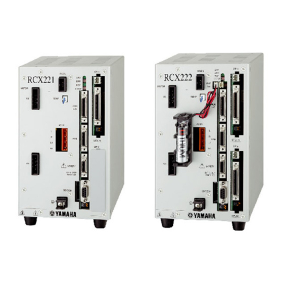
6.1 Controller 6.1.3.2 RCX221 Standard RCX221 Bottom view 6-M3 (22) OP.1 RGEN RCX221 MOTOR E-STOP TEMP ACIN OP.2 SAFETY EXT.E-STOP PIN11-12 SD/COM unit: mm RCX221 with RG2 option installed Bottom view 6-M3 (22) OP.1 RGEN RCX221 MOTOR E-STOP RGEN TEMP ACIN TEMP OP.2... -
Page 86: Rcx221Hp
6.1 Controller 6.1.3.3 RCX221HP RCX221HP (High power version) Bottom view 6-M3 (22) OP.1 RGEN RCX221 MOTOR E-STOP TEMP ACIN OP.2 SAFETY EXT.E-STOP PIN11-12 SD/COM unit: mm RCX221HP with RG2 option installed Bottom view 6-M3 (22) OP.1 RGEN RCX221 MOTOR E-STOP RGEN TEMP ACIN... -
Page 87: Rcx222
6.1 Controller 6.1.3.4 RCX222 Standard RCX222 Bottom view 6-M3 (22) OP.1 RGEN RCX222 E-STOP MOTOR TEMP ACIN OP.2 SAFETY EXT.E-STOP PIN11-12 SD/COM unit: mm RCX222 with RG2 option installed Bottom view 6-M3 (22) OP.1 RGEN RCX222 E-STOP MOTOR RGEN TEMP ACIN TEMP OP.2... -
Page 88: Rcx222Hp
6.1 Controller 6.1.3.5 RCX222HP RCX222HP (High power version) Bottom view 6-M3 (22) OP.1 RGEN RCX222 E-STOP MOTOR TEMP ACIN OP.2 SAFETY EXT.E-STOP PIN11-12 SD/COM unit: mm RCX222HP with RG2 option installed Bottom view 6-M3 (22) OP.1 RGEN RCX222 E-STOP MOTOR RGEN TEMP ACIN... -
Page 89: Programming Box
6.2 Programming box 6.2 Programming box CAUTION Specifi cations and appearance are subject to change without prior notice. 6.2.1 Basic specifications 6.2.1.1 RPB-E Item RPB-E Liquid crystal display (40 characters × 15 lines) Display screen * Effective number of lines for RCX221/RCX222: 8 lines Emergency stop button Normally-closed contact (with lock function) Enable switch... -
Page 90: External View
6.2 Programming box 6.2.2 External view 6.2.2.1 RPB-E RPB-E external view Selector switch 50.2 Enable switch unit: mm 6-16 Chapter 6 SPECIFICATIONS... - Page 91 MEMO...
- Page 92 All rights reserved. No part of this publication may be reproduced in any form without the permission of YAMAHA MOTOR CO., LTD. Information furnished by YAMAHA in this manual is believed to be reliable. However, no responsibility is assumed for possible inaccuracies or omissions.