Table of Contents
Advertisement
Quick Links
Advertisement
Table of Contents
Troubleshooting

Related Manuals for Yamaha SRCP


Summary of Contents for Yamaha SRCP
- Page 1 YAMAHA SINGLE-AXIS ROBOT CONTROLLER SRCP User’s Manual ENGLISH E84-Ver. 2.04...
-
Page 3: Table Of Contents
Installing current control switches ... 2-5 2-2-6 Insulation resistance and voltage breakdown tests ... 2-5 Grounding ... 2-5 Connecting the SRCP to the Control Unit ... 2-5 Connecting to the Robot ... 2-6 2-5-1 Robot I/O connector and signal table ... 2-6 2-5-2 Motor connector and signal table ... - Page 4 Chapter 4 BASIC OPERATION OF THE TPB ... 4-1 Connecting and Disconnecting the TPB ... 4-2 4-1-1 Connecting the TPB to the SRCP controller ... 4-2 4-1-2 Disconnecting the TPB from the SRCP controller ... 4-3 Basic Key Operation ... 4-4 Reading the Screen ...
- Page 5 Robot Language Description ... 8-6 8-4-1 MOVA ... 8-6 8-4-2 MOVI ... 8-6 8-4-3 MOVF ... 8-7 8-4-4 JMP ... 8-7 8-4-5 JMPF ... 8-8 8-4-6 JMPB ... 8-9 8-4-7 L ... 8-9 8-4-8 CALL ... 8-10 8-4-9 DO ... 8-10 8-4-10 WAIT ...
- Page 6 10-6 Using a Memory Card ... 10-14 10-6-1 Saving controller data to a memory card ... 10-14 10-6-2 Loading data from a memory card ... 10-16 10-6-3 Formatting a memory card ... 10-18 10-6-4 Viewing the ID number for memory card data ... 10-19 10-7 Duty (load factor) monitor...
- Page 7 Chapter 15 SPECIFICATIONS ... 15-1 15-1 SRCP sereis ...15-2 15-1-1 Basic specifications ... 15-2 15-1-2 Robot number list ... 15-3 15-1-3 LED display ... 15-3 15-2 TPB ...15-4 15-2-1 Basic specifications ... 15-4 15-3 Regenerative Unit (RGU-2) ... 15-5 15-3-1 Basic specifications ... 15-5 15-3-2 Dimensions ...
- Page 8 MEMO...
-
Page 9: Chapter 1 Overview
This first chapter explains basic information you should know before using the SRCP controller such as names and functions of the various parts, steps necessary to prepare the robot for operation, and the architecture of the system... -
Page 10: Features Of The Srcp Series Controller
■ The I/O interface supports pulse trains to allow position control by input of a pulse train. NOTE The SRCP controller can be operated from either a TPB (programming box) or a PC running with communication software such as POPCOM. This user's manual mainly describes operations using the TPB. For details on operation with POPCOM, refer to the POPCOM manual. -
Page 11: Setting Up For Operation
Setting Up for Operation The chart below illustrates the basic steps to follow from the time of purchase of this controller until it is ready for use. The chapters of this user's manual are organized according to the operation proce- dures, and allow first time users to proceed one step at a time. -
Page 12: External View And Part Names
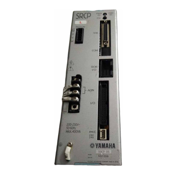
1-3 External View and Part Names This section explains part names of the SRCP controller and TPB along with their functions. Note that the external view and specifications are subject to change without prior notice to the user. 1-3-1 SRCP controller External View and Part Names 1. - Page 13 Fig. 1-1 Exterior of the SRCP controller SRCP-05 SRCP-05A, 10A, 20A 1-3 External View and Part Names SRCP-10, 20...
- Page 14 1-3 External View and Part Names Fig. 1-2 Three-side view of the SRCP controller SRCP-05 注意 CAUTION 高温注意 HIGH TEMPERATURE SRCP-10, 20 SRCP-05A, 10A, 20A SRCP MOTOR ACIN 200-230V~ 50-60Hz MAX. 400VA SRCP 05 MODEL. SER. NO. FACTORY AUTOMATION EQUIPMENT MADE IN JAPAN...
-
Page 15: Tpb
The TPB can be operated in interactive data entry mode. Instructions are input through the control keys while reading the contents on the LCD screen. 4. Connection Cable This cable connects the TPB to the SRCP controller. 5. DC Power Input Terminal Not used. -
Page 16: System Configuration
1-4 System Configuration 1-4-1 System configuration The SRCP controller can be combined with various peripheral units and optional products to configure a robot system as shown below. Fig.1-5 System configuration diagram System Configuration SRCP Controller RS-232C communication control I/O control... -
Page 17: Accessories And Options
The following options are available for the SRCP controller: 1. TPB This is a hand-held programming box that connects to the SRCP controller for teaching point data, editing robot programs and operating the robot. The TPB allows interactive user opera- tion by simple menus so that even first-time users can easily operate the robot with the TPB. - Page 18 MEMO...
-
Page 19: Chapter 2 Installation And Connection
Chapter 2 INSTALLATION AND CONNECTION This chapter contains precautions that should be observed when installing the controller, as well as procedures and precautions for wiring the controller to the robot and to external equipment. -
Page 20: Installing The Srcp Controller
2-1-1 Installation method Using the L-shaped brackets attached to the top and bottom of the controller, install the controller from the front or rear position. (See Fig.1-2 Three-side view of the SRCP controller.) 2-1-2 Installation location Installing the SRCP Controller ■... -
Page 21: Connecting The Power Supply
If the power supply voltage drops below the above range during operation, the alarm circuit will work and return the SRCP controller to the initial state the same as just after power-on, or stop operation. To avoid this problem, use a regulated power supply with voltage fluctuations of less than ±10%. -
Page 22: Installing An External Leakage Breaker
To ensure safety, a circuit protector must be installed in the power supply connection section of the robot controller. An inrush current, which might be from several to nearly 20 times higher than the rated current, flows at the instant that the SRCP controller is turned on or the robot motors start to operate. -
Page 23: Installing Current Control Switches
The SRCP controller can be operated either through the TPB programming box or through a PC (personal computer) equipped with an RS-232C terminal. When using the TPB, plug the TPB cable connector into the TPB connector of the SRCP controller. (Refer to "4-1-1 Connecting the TPB to the SRCP controller".) When using a PC, plug the RS-232C interface cable connector (25 pins) into the TPB connector of the SRCP controller. -
Page 24: Connecting To The Robot
2-5 Connecting to the Robot First make sure that the power to the SRCP controller is turned off, and then connect the robot cable to the robot I/O connector and motor connector on the front panel of the SRCP controller. Fully insert the robot cable until it clicks in position. -
Page 25: Connecting To The I/O. Cn Connector
The I/O. CN connector is used for connecting the SRCP controller to external equipment such as a PLC. When using external equipment for I/O control, connect the wiring to the I/O. CN connector (with a flat cable) supplied as an accessory and then plug it into the I/O. CN connector on the SRCP controller. -
Page 26: Connecting To The Ext. Cn Connector
Unless these terminals are shorted, emergency stop is always activated to prohibit the robot from operating. DANGER Be sure to turn off the power to the entire robot system before doing any wiring to the SRCP controller. Failure to do so may cause electrical shocks. -
Page 27: Connecting To The Regenerative Unit
Connecting to the Regenerative Unit Some types of robots must be connected to a regenerative unit. In such cases, use the interconnection cable to connect the SRCP controller to the regenerative unit. Fig. 2-3 Connecting the SRCP controller to a regenerative unit Use the interconnection cable to make connections. - Page 28 MEMO...
-
Page 29: Chapter 3 I/O Interface
I/O INTERFACE The SRCP series has I/O interface connectors (EXT. CN and I/O. CN) as a standard feature. The EXT. CN is used for emergency stop input and 24V power input for I/O control. The I/O. CN consists of an interlock input, 7 dedicated command inputs, 3 dedicated outputs, 8 general-purpose inputs, 5 general-purpose outputs, feedback pulse outputs, etc. -
Page 30: I/O Signals
3-1-1 I/O. CN connector signals The I/O. CN connector of the SRCP controller has 40 pins, with an individual signal assigned to each pin. The following table shows the pin number as well as the name and description of each signal assigned to each pin. -
Page 31: Input Signal Description
3-2-1 Dedicated command input The dedicated command input is used to control the SRCP controller from a PLC or other external equipment. To accept this input, the READY, BUSY and LOCK signals must be set as follows. - Page 32 3-2 Input Signal Description ■ Absolute point movement command (ABS-PT) ■ Relative point movement command (INC-PT) ■ Automatic operation start command (AUTO-R) ■ Step operation start command (STEP-R) This command moves the robot to an absolute position specified by a point number at a specified speed along an axis coordinate whose origin is defined as 0.
- Page 33 "9-4 Switching the Execution Program".) The lead program can also be selected by executing a communication command "@SWI". It may also be selected when the program data is loaded into the SRCP controller from the memory card. 3-2 Input Signal Description...
-
Page 34: General-Purpose Input (Di0 To Di7)
3-2 Input Signal Description 3-2-2 General-purpose input (DI0 to DI7) These general-purpose inputs are available to users for handling data input in a program. These inputs are usually connected to sensors or switches. These inputs can also be directly con- nected to a PLC output circuit. -
Page 35: Service Mode Input (Svce)
(SERVO). The servo will turn on to enable robot operation. The TPB or PC can also be used to reset emergency stop when the SRCP controller is connected to the TPB or PC. -
Page 36: Output Signal Description
BUSY signal cannot turn off even after the command execution is complete. As long as the BUSY signal is on, the SRCP controller will not accept other dedicated command inputs or commands from the TPB or PC. Avoid operating the TPB while the SRCP controller is being operated through the I/O interface. -
Page 37: General-Purpose Output (Do0 To Do4)
LED lamps. These outputs of course, can be directly connected to a PLC input circuit. All general-purpose outputs are reset (turned off) when the SRCP controller is turned on or the program is reset. * When PRM33 ("Operation at return-to-origin complete" parameter) is set to 1 or 3, DO4 does not turn off even if the program is reset. -
Page 38: I/O Circuits
3-4 I/O Circuits This section provides the SRCP controller I/O circuit specifications and examples of how the I/O circuits should be connected. Refer to these specifications and diagrams when connecting to external equipment such as a PLC. 3-4-1 I/O circuit specifications I/O Circuits ■... -
Page 39: I/O Circuit And Connection Example
3-4-2 I/O circuit and connection example I/O circuit and connection example Push-button NPN transistor Incandescent lamp Solenoid valve External DC24V power supply Pulse output circuit connection example 26LS32 or equivalent 3-4 I/O Circuits Photocoupler Input signal Output signal Controller side Controller side 26LS31 or equivalent PZM+... -
Page 40: I/O Connection Diagram
3-5-1 Connection to PLC output unit Connection to the Mitsubishi I/O Connection Diagram © PLC AY51 output unit AY51 type output unit DC24V DC24V SRCP series controller I/O. CN TB 1 DI 0 DI 1 DI 2 DI 3 DI 4... -
Page 41: Connection To Plc Input Unit
3-5-2 Connection to PLC input unit Connection to the Mitsubishi © PLC AX41 input unit SRCP series controller I/O. CN READY BUSY DO 0 DO 1 DO 2 DO 3 DO 4 EXT. CN External DC 24V power supply 3-5 I/O Connection Diagram... -
Page 42: I/O Control Timing Charts
AC power supply 500ms or more ■ The SRCP initial state depends on whether emergency stop is triggered when the power is turned on. When the power is turned on while emergency stop is cancelled, the SRCP controller starts with the READY signal and also the servo turned on. -
Page 43: When Executing A Dedicated Input Command
3-6-2 When executing a dedicated input command ■ The BUSY signal turns on when a dedicated command is received. Whether the received com- mand has ended normally can be checked with the END signal status at the point that the BUSY signal turns off. - Page 44 3-6 I/O Control Timing Charts (2)When a command with a short execution time runs and ends normally: (Command execution has already ended and the END signal is on before turning off (contact open) the dedicated command input, as in the examples listed below.) •...
- Page 45 (3)When a command cannot be executed from the beginning: (Command execution is impossible from the beginning and the END signal does not turn on, as in the examples listed below.) • A movement command (ABS-PT, INC-PT) was executed without return-to-origin being com- pleted.
-
Page 46: When Interlock Signal Is Input
3-6 I/O Control Timing Charts (4)When command execution cannot be completed: 3-6-3 When interlock signal is input (Command execution stops before completion and the END signal does not turn on, as in the examples listed below.) • An interlock or emergency stop was triggered during execution of a dedicated command. •... -
Page 47: When Emergency Stop Is Input
3-6-4 When emergency stop is input Dedicated command BUSY READY ■ The READY signal turns off. The BUSY signal also turns off while a dedicated command is being executed. The END signal remains unchanged. ■ To enable robot operation, cancel emergency stop to turn on the READY signal, then input the servo recovery command (SERVO). -
Page 48: When Executing A Point Movement Command
3-6 I/O Control Timing Charts 3-6-6 When executing a point movement command ■ When executing a point movement command (ABS-PT, INC-PT), the point data and speed data must first be input before inputting the command. The point data and speed data can be specified with DI0 to DI7 (or DI0 to DI6 when SERVICE mode is enabled). -
Page 49: Chapter 4 Basic Operation Of The Tpb
Chapter 4 BASIC OPERATION OF THE TPB The TPB is a hand-held, pendant-type programming box that connects to the SRCP controller to edit or run pro- grams for robot operation. The TPB allows interactive user operation on the display screen so that even first-time users can easily operate the robot with the TPB. -
Page 50: Connecting And Disconnecting The Tpb
Connecting and Disconnecting the TPB CAUTION Do not modify the TPB cable or use any type of relay unit for connecting the TPB to the SRCP controller. Doing so might cause communication errors or malfunctions. Connect the TPB connector to the connec- tor labelled "TPB"... -
Page 51: Disconnecting The Tpb From The Srcp Controller
4-1 Connecting and Disconnecting the TPB 4-1-2 Disconnecting the TPB from the SRCP controller To disconnect the TPB from the controller while a program or an I/O dedicated command is being executed, pull out the TPB while holding down the ESC switch on the front panel of the controller. -
Page 52: Basic Key Operation
4-2 Basic Key Operation 1) Selectable menu items are displayed on the 4th 2) On the initial screen shown in A, pressing a 3) If an error occurs during operation, a buzzer 4) If an alarm occurs during operation, its alarm Basic Key Operation line (bottom line) of the TPB screen. -
Page 53: Reading The Screen
Reading the Screen The following explains the basic screen displays and what they mean. 4-3-1 Program execution screen The display method slightly differs depending on the version of TPB. Ver. 12.50 or earlier [OPRT-STEP] 100 0:31 062:MOVA 200,100 0.00] 1SPD 2RSET3CHG 4next 1. -
Page 54: Point Edit Screen (Teaching Playback)
4-3 Reading the Screen 4-3-3 Point edit screen (teaching playback) 4-3-4 DIO monitor screen 1. General-purpose input From left 2. Dedicated input From left [EDIT-PNT-TCH](1)100 P255 = 123.45 1CHG 2SPD 3S_SET4next 1. Current mode 2. Speed selection number 3. Speed parameter (%) 4. -
Page 55: Hierarchical Menu Structure
Hierarchical Menu Structure INFORMATION (System information) (Program Edit) EDIT (Editing) (Point Edit) UTL (Utility) (Origin Return) POWER STEP OPRT (Step Run) (Operation) AUTO (Auto Run) (Parameter Setting) B.UP (Backup) (System) INIT (Initialization) SAFE (Safety Setting) OPT (Option) UTL (Utility) DIO (DIO Monitor) (Monitor) DUTY (DUTY Monitor) The menu hierarchy slightly differs depending on the versions of the controller and TPB. -
Page 56: Restricting Key Operation By Access Level
4-5 Restricting Key Operation by Access Level The TPB key operations can be limited by setting the access levels (operation levels). A person not trained in robot operation might accidentally damage the robot system or endanger others by using the TPB incorrectly. Set the access levels to restrict TPB key operations and prevent such accidents. -
Page 57: Changing An Access Level
Memory card Level All operations are permitted. Loading the parameters and all data to the SRCP is prohibited. (Point data or program data can be loaded.) Loading any data to the SRCP is prohibited. (Data can be saved and the memory card formatted.) Use of memory card is prohibited. - Page 58 6. NOTE The password is identical to the SRCP controller's version number. For example, if the controller version is 24.00, enter 24.00 as the password. Once the password is accepted, it will not be requested unless the TPB is disconnected from the controller or the controller power is turned off.
-
Page 59: Chapter 5 Parameters
The SRCP controller uses a software servo system, so no adjustment of hardware components such as potentiometers or DIP switches are required. Instead, the SRCP controller uses parameters that can be easily set or changed by the TPB or PC (personal computer). -
Page 60: Setting The Parameters
5-1 Setting the Parameters 1) On the initial screen, press 2) Next, press 3) Select the parameter group you want to edit. 4) The current PRM0 (robot type number ) set- 5) When the desired parameter is displayed, enter 6) When the setting is complete, the cursor moves Setting the Parameters (SYS). -
Page 61: Parameter Description
Parameter Description The parameters are described in order below. CAUTION Parameters not displayed on the TPB screen are automatically set or optimized to match the robot type when the robot parameters are initialized. You usually do not have to change these parameter settings. If for some special reason you need to change or check these hidden parameters, use any of the following methods. - Page 62 5-2 Parameter Description PRM3: PRM4: PRM5: PRM6: Payload This specifies the total weight of the workpiece and tool attached to the robot. In cases where this weight varies, enter the maximum payload. Based on this parameter, the controller determines the optimum acceleration speed for the robot, so ensure that the correct payload is set.
- Page 63 PRM7: I/O point movement command speed This parameter sets the movement speed to execute a point movement command (ABS- PT, INC-PT) and also determines the number of points that can be used with a point movement command. (See "3-2-2 General-purpose input (DI0 to DI7)".) Input range: 0 to 100 (%) Default value: 100...
- Page 64 This parameter indicates the constant that is determined by the linear scale. Default value: Depends on robot type. This parameter specifies the origin (reference point) detection method. The SRCP control- ler uses the stroke-end detection method. Default value: 1 (Stroke-end detection method) CAUTION The origin detection method is predetermined by the machine specifications.
- Page 65 PRM18: Speed integration gain This sets the speed control gain. Typically, PRM17 and PRM18 should be input at a ratio of 3 : 2. Generally, the larger the gain, the higher the acceleration will be. However, if the gain is set too high, abnormal oscillation or noise might be generated, causing serious problems in the robot and controller.
- Page 66 5-2 Parameter Description PRM24: Teaching count data (TPB entry) PRM25: Not used PRM26: Teaching movement data PRM27: Teaching movement data 1 (for TPB) PRM28: Teaching movement data 2 (for TPB) PRM29: Teaching movement data 3 (for TPB) PRM30: Maximum program speed PRM31: Mechanical lock detection level This is entered in the TPB and cannot be used.
- Page 67 PRM32: Alarm number output When an alarm is issued, this parameter selects whether the alarm number is to be output as a general-purpose output. When this parameter is set to 1, the alarm number is output as a 5-bit binary signal through DO0 to DO4. Input range: 0 or 1 Meaning:...
- Page 68 Example: To turn off the END output sequence after the controller has started normally, and disable the This parameter specifies the system operation mode. When you want to use the SRCP series in operating specifications that differ from normal mode, change this parameter as explained below.
- Page 69 Bit 7: END output sequence setting at command execution completion (supported by Ver. 24.32 and later versions): This selects the END output sequence at dedicated command completion. With the standard setting ("0"), the command's execution result is output to the END output when the command is completed.
- Page 70 5-2 Parameter Description PRM41: I/O point movement command speed 1 PRM42: I/O point movement command speed 2 PRM43: I/O point movement command speed 3 PRM44: Maximum speed setting PRM45: Feed forward gain This parameter sets the speed at which the robot moves when a point movement command (ABS-PT, INC-PT) is executed.
- Page 71 PRM46: Servo status output This parameter selects whether to output the axis servo status as a general-purpose output. When this parameter is set to 1, DO3 turns on and off along with servo on/off. Input range: 0 or 1 Meaning: 0: Does not output the servo status.
- Page 72 5-2 Parameter Description PRM51: Lead program number PRM52: Hold gain PRM53: Zone output selection This parameter sets the lead program number. Default value: 0 NOTE The lead program is the program that has been selected as the execution program by the TPB or POPCOM. (See "9-4 Switching the Execution Program".) The lead program can also be selected by executing a communication command "@SWI".
- Page 73 Zone output function To use the zone output function, the desired zone must be specified with point data. (See Chapter 7, "EDITING POINT DATA".) When the robot enters the specified zone, its re- sult is output to the specified port. Point numbers and output port that can be used for each zone output are listed below.
- Page 74 5-2 Parameter Description PRM54: Magnetic pole detection level PRM55: Magnetic pole position PRM56: Controller version 2 PRM57: Servo braking selection (available for version 24.15 or later) PRM58: Not used PRM59: Not used PRM60 to 63: Spare PRM64 to 99: Data area for pulse trains Default value: Depends on the robot.
-
Page 75: Chapter 6 Programming
Chapter 6 PROGRAMMING In this chapter we will try programming some operations. First, you will learn how to enter a program using the TPB programming box. -
Page 76: Basic Contents
6-1 Basic Contents 6-1-1 Robot language and point data The SRCP controller uses the YAMAHA robot language that is very similar to BASIC. It allows you to easily create programs for robot operation. In programs created with the YAMAHA robot language, the robot position data (absolute position, amount of movement) are not expressed in terms of direct numeric values. -
Page 77: Editing Programs
Editing Programs "Program editing" refers to operations such as creating a program right after initialization, creating a new program, changing an existing program, and deleting or copying a program. In this section, you will learn the basic procedures for program editing using the TPB. "Creating a program right after initialization"... -
Page 78: Creating Programs After Initialization
6-2 Editing Programs 6-2-1 Creating programs after initialization 1) On the initial screen, press 2) Next, press 3) Since no program is registered after initializa- 4) Press the 5) When you selected 6) Select (EDIT). (PGM). tion, an error message appears on the screen, indicating that no program exists. - Page 79 7) After selecting the robot language command, enter the operand data. When you press , the cursor moves to op- erand 1, so enter the data with the number keys. (Do not press at this point.) While pressing – to move the cur- sor, enter all necessary operand data as needed.
-
Page 80: Creating A New Program
6-2 Editing Programs 6-2-2 Creating a new program 1) On the initial screen, press 2) Next, press 3) The execution program number and step are 4) Enter the new program number with the number 5) A confirmation message appears. Make sure the 6) Proceed with program editing by following step (EDIT). -
Page 81: Adding A Step
6-2-3 Adding a step 1) On the initial screen, press (EDIT). 2) Next, press (PGM). 3) The execution program number and step are displayed on the screen. Press (CHG) here. 4) Enter the program number you want to edit with the number keys and press 5) Enter the last step number with the number keys and press... - Page 82 6-2 Editing Programs 7) Select 8) After selecting the robot language command, 9) After entering the operand data, press 10)When the program has been edited correctly, or a robot language com- mand shown on the lower part of each number key.
-
Page 83: Correcting A Step
6-2-4 Correcting a step 1) Use the same procedure up to step 4 in "6-2-3 Adding a step". 2) Enter the number of the step you want to cor- rect with the number keys and press 3) Press (MOD). 4) Select or a robot language com- mand shown on the lower part of each number key. -
Page 84: Inserting A Step
6-2 Editing Programs 6-2-5 Inserting a step 1) Use the same procedure up to step 4 in "6-2-3 2) Enter the number of the step where you want 3) Press 4) Select 5) After selecting the robot language command, 6) After entering the operand data, press 7) When entry is completed correctly, the screen Adding a step". -
Page 85: Deleting A Step
6-2-6 Deleting a step 1) Use the same procedure up to step 4 in "6-2-3 Adding a step". 2) Enter the number of the step you want to delete with the number keys and press 3) Press (DEL). 4) A confirmation message appears. To delete the step, press (yes). -
Page 86: Program Utility
6-3 Program Utility 6-3-1 Copying a program 1) On the initial screen, press 2) Next, press 3) Press 4) Enter the program number you want to copy 5) Enter the program number you want to copy to Program Utility (EDIT). (UTL). -
Page 87: Deleting A Program
6) If program data is already registered with the selected program number, a confirmation mes- sage appears. To overwrite the program, press To cancel, press (no). 7) When the program has been copied, the screen returns to step 3. 6-3-2 Deleting a program 1) Use the same procedure up to step 2 in "6-3-1 Copying a program". -
Page 88: Viewing The Program Information
6-3 Program Utility 6-3-3 Viewing the program information 1) Use the same procedure up to 2 in "6-3-1 Copy- 2) Press 3) The program numbers are displayed on the 4) Press the ing a program". (LIST). screen, along with the number of registered steps and the number of available remaining steps. -
Page 89: Chapter 7 Editing Point Data
Chapter 7 EDITING POINT DATA There are three methods to enter point data: manual data input (MDI), teaching playback, and direct teaching. Manual data input allows you to directly enter point data with the TPB number keys. Teaching playback moves the robot in manual operation to a desired position and then obtains that position as point data. -
Page 90: Manual Data Input
7-1 Manual Data Input 1) On the initial screen, press 2) Next, press 3) Press 4) The currently selected point data in the execu- 5) Enter the point number you want to edit with 6) Enter the point data with the number keys and 7) The input data is then registered as point data. -
Page 91: Teaching Playback
Teaching Playback 1) On the initial screen, press (EDIT). 2) Next, press (PNT). 3) Press (TCH). 4) The currently selected point data in the execu- tion program appears on the screen. If you want to edit another point data, press the keys to scroll the point data. - Page 92 7-2 Teaching Playback 6) Move the robot to the teaching position with 7) Three different speed settings, SPEED (1), 8) Move the robot to the teaching position in this – keys. Each time the key is pressed, the robot moves a certain amount in the direction indicated by the key and then stops.
-
Page 93: Direct Teaching
Direct Teaching 1) On the initial screen, press (EDIT). 2) Next, press (PNT). 3) Press (DTCH). 4) Following the message, press the emergency stop button on the TPB. 5) The currently selected point data in the execu- tion program appears on the screen. If you want to edit another point data, press the keys to scroll the point data. - Page 94 7-3 Direct Teaching 7) Move the robot to the teaching position by hand. 8) Press 9) Following the message, release the emergency 10)A confirmation message appears asking 11)The screen returns to step 3. to input the current position as point data.
-
Page 95: Manual Control Of General-Purpose Output
I/O interface to operate a gripper or other tools, you may want to check the position of workpiece by actually moving it. For this reason, the SRCP controller is designed to allow manual control of general-purpose outputs from the TPB. -
Page 96: Manual Release Of Holding Brake
7-5 Manual Release of Holding Brake The holding brake on the vertical type robot can be released. Since the movable part will drop when the brake is released, attaching a stopper to protect the tool tip from being damaged is recommended. 1) Use the same procedure up to step 4 in "7-3 2) Press 3) A confirmation message appears asking... -
Page 97: Deleting Point Data
Deleting Point Data 1) Use the same procedure up to step 2 in "7-1 Manual Data Input". 2) Press (DEL). 3) Enter the point number at the start to delete point data with the number keys and press 4) Enter the point number at the end to delete point data with the number keys and press 5) A confirmation message appears asking whether to delete the data. -
Page 98: Tracing Points (Moving To A Registered Data Point)
7-7 Tracing Points (Moving to a registered data point) The robot can be moved to the position specified by a registered data point. You can check the input point data by actually moving the robot. 1) Use the same procedure up to step 5 in "7-2 2) Press 3) The coordinate data of the movement destina- 4) When the movement is completed, the screen... -
Page 99: Chapter 8 Robot Language
This chapter explains the robot language. It describes what kind of commands are available and what they mean. The SRCP series uses the YAMAHA robot language. This is an easy-to-learn BASIC-like programming language. Even a first-time user can easily create programs to control complex robot and peripheral device movements. -
Page 100: Robot Language Table
8-1 Robot Language Table Instruction MOVA MOVI MOVF JMPF JMPB CALL WAIT TIMR SRVO STOP ORGN TOFF JMPP MSEL MOVM JMPC JMPD CSEL SHFT Values in brackets [ ] can be omitted. Robot Language Table Description and Format Moves to point data position. MOVA <point number>, <maximum. -
Page 101: Robot Language Syntax Rules
Robot Language Syntax Rules 8-2-1 Command statement format The robot language command statement format for the SRCP controller is as follows. When creating a program using the TPB, each command statement can be automatically entered in this format, so you do not have to be aware of this format while creating the program. -
Page 102: Variables
8-2 Robot Language Syntax Rules 8-2-2 Variables Variable are used in a program to hold data. The following variables can be used with the SRCP controller. ■ Point variable P ■ Counter array variable C, Counter variable D ■ Flag variable: memory input/output 100 to 147 Memory I/O description A point variable can contain a point number. -
Page 103: Program Function
Strictly speaking, if the CPU is one unit, it executes two or more programs (tasks) while switching between them in an extremely short time almost as if they were being simultaneously executed. The SRCP controller uses this multi-task function to perform multiple tasks while switching the programs within a very short time (5ms maximum). -
Page 104: Robot Language Description
8-4 Robot Language Description 8-4-1 MOVA 8-4-2 MOVI Robot Language Description Function: Moves to a point specified by a point number (Moves to an absolute position relative to the origin point). Format: MOVA <point number>, <maximum speed> Example: MOVA 51, 80 Moves to P51 at speed 80. -
Page 105: Movf
8-4-3 MOVF Function: Moves until a specified DI number input is received. Format: MOVF <point number> <DI number> <DI status> Example: MOVF 1, 2, 1 The robot moves toward P1 and stops when DI2 turns on. Program ex- ecution then proceeds to the next step. Explanation: This is used when searching for a target position using sensors or other devices. -
Page 106: Jmpf
8-4 Robot Language Description 8-4-5 JMPF General-purpose input status and input condition value when the number of conditional input points is 4 (input range 0 to 15) Function: If the conditional jump input matches the setting value, program execu- tion jumps to a specified label in a specified program. Format: JMPF <label number>, <program number>, <input condition value>... -
Page 107: Jmpb
8-4-6 JMPB Function: Jumps to a specified label when a specified general-purpose input or memory input is ON or OFF. Format: JMPB <label number>, <DI or MI number>, <input status> Example: JMPB 12, 2, 1 Jumps to label 12 when DI2 input is ON. If DI2 is OFF, the program execution proceeds to the next step. -
Page 108: Call
8-4 Robot Language Description 8-4-8 CALL 8-4-9 DO Function: Calls and executes another program. Format: CALL <program number>, <number of times> Example: CALL 5, 2 Calls program 5 and executes it twice. Program execution then proceeds to the next step. Explanation: When repeating the same operation a number of times, the CALL state- ment is used as needed to call and execute the subroutine defined as a... -
Page 109: Wait
8-4-10 WAIT Function: Waits until a specified general-purpose input or memory input changes to a specified state. Format: WAIT <DI or MI number>, <input status> Example: WAIT 5, 1 Waits until DI5 turns on. Explanation: This command adjusts the timing according to the general-purpose in- put or memory input state. - Page 110 8-4 Robot Language Description 8-4-12 P 8-4-13 P+ 8-4-14 P- Function: Sets a point variable P. Format: <point number> Example: Sets a point variable P to 200. Explanation: The point variable can contain a point number as a variable, which can be from 0 to 999.
-
Page 111: Srvo
8-4-15 SRVO Function: Turns the servo on and off. Format: SRVO <servo status> Example: SRVO This turns the servo on. SRVO This turns the servo off. Explanation: This command is used to prevent an overload on the motor that may occur if the robot is locked mechanically after positioning is completed. -
Page 112: Orgn
8-4 Robot Language Description 8-4-17 ORGN Function: Performs return-to-origin by using the stroke-end detection method. Format: ORGN Example: ORGN Performs return-to-origin by the stroke-end detection method. Explanation: Return-to-origin is performed based on return-to-origin parameter data. Others: • The magnetic pole is detected simultaneously with return-to-origin operation. -
Page 113: Ton
8-4-18 TON Function: Executes a specified task. Format: <task number>, <program number>, <start type> Example: 1,2,0 Newly executes program 2 as task 1. Explanation: This command starts multiple tasks and can be used to control the I/O signals in parallel with the axis movement and perform different process- ing for each axis. -
Page 114: Jmpp
8-4 Robot Language Description 8-4-20 JMPP Function: Jumps to a specified label when the axis position relation meets the speci- fied conditions. Format: JMPP <label number>, <axis position condition> Example: JMPP Jumps to label 3 if the X-axis position is smaller than the point specified with the point variable P. -
Page 115: Mat
You do not have to enter any data in p253 and p254 (when pallet number is 0). • The matrix definition contents are shared with each task. • Because only a single-axis robot is controlled with the SRCP series, the actual movement is linear even if a 2-dimensional matrix is de- fined. -
Page 116: Msel
8-4 Robot Language Description 8-4-22 MSEL Function: Specifies a matrix where the robot moves with a MOVM statement. Format: MSEL <pallet number> Example: MSEL Points where the robot moves with a MOVM statement are calculated based on matrix data of pallet number 0. Explanation: This command selects a matrix and is always used with a MOVM state- ment as a pair. -
Page 117: Movm
• The MOVM statement performs calculation on the assumption that the robot operates on the Cartesian coordinate system. • Because only a single-axis robot is controlled with the SRCP series, the actual movement is linear even if a 2-dimensional matrix is de- fined. -
Page 118: Jmpc
8-4 Robot Language Description 8-4-24 JMPC 8-4-25 JMPD Function: Jumps to a specified label when the counter array variable C matches a specified value. Format: JMPC <label number>, <counter value> Example: JMPC 5, 100 Jumps to label 5 when the counter array variable C is 100. Program execution proceeds to the next step except when the counter array vari- able C is 100. -
Page 119: Csel
8-4-26 CSEL Function: Specifies an array element of the counter array variable C to be used. Format: CSEL <array element number> Example: CSEL The counter array variable of element number 1 is used in the subse- quent steps. Explanation: This command designates an array element number of the counter array variable C. - Page 120 8-4 Robot Language Description 8-4-28 C+ 8-4-29 C- 8-4-30 D 8-4-31 D+ Function: Adds a specified value to the counter array variable C. Format: [<addition value>] Example: Adds 100 to the counter array variable C. (C←C+100) Adds 1 to the counter array variable C. (C←C+1) Explanation: This command adds a specified value to the counter array variable C specified with the CSEL statement.
-
Page 121: Shft
8-4-32 D- Function: Subtracts a specified value from the counter variable D. Format: [<subtraction value>] Example: Subtracts 100 from the counter variable D. (D←D-100) Subtracts 1 from the counter variable D. (D←D-1) Explanation: This command subtracts a specified value from the counter variable D. The subtraction value can be set to any value from 1 to 65535. -
Page 122: Sample Programs
8-5 Sample Programs 8-5-1 Moving between two points 8-5-2 Moving at an equal pitch Sample Programs Program Comment [NO0] ; Label definition 001: L ; Moves to P1 002: MOVA ; Moves to P2 003: MOVA ; Delays for one second 004: TIMR : Returns to L0 005: JMP... -
Page 123: Positioning 2 Points And Sending Job Commands To A Plc At Each Position
8-5-3 Positioning 2 points and sending job commands to a PLC at each position Job 1 Point Position at which job 1 is complete Position at which job 2 is complete General-purpose input Job 1 completion 1: Complete 0: Not complete Job 2 completion 1: Complete 0: Not complete General-purpose output Job 1 command 1: Output... -
Page 124: Robot Stands By At P0, And Moves To P1 And Then To P2 To Pick And Place A Workpiece
8-5 Sample Programs 8-5-4 Robot stands by at P0, and moves to P1 and then to P2 to pick and place a workpiece Upper end limit switch (DI0) Air cylinder (DO0) Lower end limit switch (DI1) Air chuck (DO1) Workpiece detection sensor (DI2) Operation Moves to the workpiece feed position from the... -
Page 125: Picking Up 3 Kinds Of Workpieces Flowing On The Front Conveyor And Placing Them On The Next Conveyors While Sorting
8-5-5 Picking up 3 kinds of workpieces flowing on the front conveyor and placing them on the next conveyors while sorting Front conveyor Workpiece Upper end limit switch (DI0) Lower end limit switch (DI1) Workpiece detection sensor (DI2 to DI4) Operation q Moves to the workpiece feed position and picks up a workpiece. - Page 126 8-5 Sample Programs Program Comment [NO1] <<Main routine>> ; Label definition 001: L ; Jumps to L2 when workpiece A is detected 002: JMPB ; Jumps to L3 when workpiece B is detected 003: JMPB ; Jumps to L4 when workpiece C is detected 004: JMPB ;...
-
Page 127: Switching The Program From I/O
(DI7 and DO0 in this case) one at a time and perform the handshake. This is for synchronizing the SRCP controller program with an external device such as a PLC. If this part is omitted, the wrong program might be selected during program selection with the JMPF statement. - Page 128 8-5 Sample Programs Program Comment [NO0] ; Label definition 001: L ; Waits for confirmation ON of the selected program 002: WAIT ; Program selection start turns on 003: DO ; Waits for confirmation OFF of the selected program 004: WAIT ;...
-
Page 129: Axis Movement And I/O Multi-Task
8-5-7 Axis movement and I/O multi-task The robot moves between two points and performs multi-task I/O operation in asynchronous mode. General-purpose input/output Job status detection Job owner's output Program [NO0] 001: TON 002: L 003: MOVA 004: TIMR 005: MOVA 006: TIMR 007: JMP Program... -
Page 130: Turning On General-Purpose Outputs During Robot Movement After A Certain Time Has Elapsed
8-5 Sample Programs 8-5-8 Turning ON general-purpose outputs during robot movement after a certain time has elapsed 3 sec. 3 sec. 3 sec. DO0=1 DO1=1 Point Start position Target position Program Comment [NO0] ; Label definition 001: L ; Moves to P0 at speed 100 002: MOVA ;... -
Page 131: Turning On A General-Purpose Output During Robot Movement When It Has Passed A Specified Position
8-5-9 Turning ON a general-purpose output during robot movement when it has passed a specified position DO0=1 Point Start position Target position Position at DO0=1 Position at DO0=0 ■ When P1 is nearer to the plus side than P0: Program [NO0] 001: L 002: MOVA... - Page 132 MEMO...
-
Page 133: Chapter 9 Operating The Robot
Chapter 9 OPERATING THE ROBOT This chapter describes how to actually operate the robot. If the program has already been completed, you will be able to operate the robot by the time you finish reading this chapter. There are two types of robot operation: step and automatic. In step operation, the program is executed one step at a time, with a step being carried out each time the RUN key on the TPB is pressed. -
Page 134: Performing Return-To-Origin
9-1 Performing Return-to-Origin The stroke-end detection is used as the origin (reference point) detection method. The following explains the procedure to perform return-to-origin using the stroke-end detection. The magnetic pole is detected simultaneously with return-to-origin operation. Each time the power is turned on, return-to-origin becomes incomplete. - Page 135 CAUTION When the SERVICE mode function is enabled, the following safety control will function. (See "10-4 SERVICE mode function".) • Return-to-origin movement speed is limited to 10mm/s or less in "SERVICE mode state" when the robot movement speed limit is enabled. •...
-
Page 136: Using Step Operation
9-2 Using Step Operation The following procedure explains how to perform step operation. In the case of a multi-task program, only the task currently selected is executed in step operation. 1) On the initial screen, press 2) Next, press 3) If the program number displayed on the screen 4) Using the number keys, enter the number of 5) The first step of the selected program is dis- 6) Enter the execution speed using the number... - Page 137 7) The screen returns to step 5. Pressing this point executes the first step. 8) This screen is displayed while the program is being executed. 9) Pressing during execution brings the ro- STOP bot to a halt and displays a message on the screen.
- Page 138 9-2 Using Step Operation 14)The screen returns to step 5, and the process is repeated from that point. CAUTION When the SERVICE mode function is enabled, the following safety control will function. (See "10-4 SERVICE mode function".) • Step operation cannot be performed in "SERVICE mode state" when automatic operation and step operation are prohibited.
-
Page 139: Using Automatic Operation
Using Automatic Operation The following procedure explains how to perform automatic operation. All the tasks started in a multi-task program are executed by automatic operation. 1) On the initial screen, press (OPRT). 2) Next, press (AUTO). 3) If the program number displayed on the screen is not the one to be run, press 4) Using the number keys, enter the number of the program to be executed and then press... - Page 140 9-3 Using Automatic Operation 8) This is the screen displayed while the program 9) Pressing 10)To switch to the display of another task in a 11)Each time you press 12)To return to the first step of the program from 13)The screen returns to step 5, and the process is is being executed.
-
Page 141: Switching The Execution Program
Switching the Execution Program The following procedure explains how to switch the program in automatic operation. Use the same procedure in step operation. The program selected by this procedure will be the lead program to which the execution sequence always returns after program reset. When the program is switched, reset is automatically performed, so all general-purpose outputs are turned off. -
Page 142: Emergency Stop Function
9-5 Emergency Stop Function There are two ways to trigger emergency stop on the SRCP controller. One way is by using the push- button on the TPB. The other is to use the I/O emergency stop input. In either case for safety reasons, a contact B (normally closed) input is used (when the contact is opened, emergency stop is triggered). - Page 143 3) After the emergency stop is released, a mes- sage appears asking whether to turn the servo To turn the servo on, press (yes). To leave the servo off , press (no). 4) Then, another message appears asking if ready to operate.
-
Page 144: Displaying The Memory I/O Status
9-6 Displaying the Memory I/O Status The memory I/O status can be displayed on the screen. 1) On the initial screen, press 2) Press 3) Press 4) The I/O status of each memory is displayed. 5) To return to the previous screen, press Displaying the Memory I/O Status (OPRT). -
Page 145: Displaying The Variables
Displaying the Variables The point data variable "P", counter array variable "C" and counter variable "D" values can be dis- played on the TPB screen. 1) On the initial screen, press (OPRT). 2) Press (STEP) or (AUTO). The following explains the procedure for dis- playing the variables on the screens in step op- eration. - Page 146 MEMO...
-
Page 147: Chapter 10 Other Operations
Chapter 10 OTHER OPERATIONS The TPB has many convenient functions in addition to those already covered. For example, memories can be initialized, and options such as memory cards can be used. This chapter will describe these additional functions... -
Page 148: Initialization
10-1 Initialization 10-1 Initialization Initializing the programs and points erases all the program data and point data currently stored in the controller. Initializing the parameters resets the parameters to their initial values. 1) On the initial screen, press 2) Next, press 3) Select the data to be initialized. - Page 149 6) Finally, enter the robot payload. Enter the payload with the number keys and then press 7) A confirmation message appears on the screen. To execute the initialization, press To cancel the initialization, press 8) When initialization is complete, the screen re- turns to step 3.
-
Page 150: Dio Monitor Display
10-2 DIO Monitor Display 10-2 DIO Monitor Display Data indicating whether the I/O signals are on or off can be displayed on the screen. The operation procedure is explained below. 10-2-1 Display from the monitor menu 1) On the initial screen, press 2) Next, press 3) The ON/OFF status of I/O signals is displayed. -
Page 151: Display From The Dio Key Operation
10-2-2 Display from the DIO key operation 1) Hold down the key. 2) The ON/OFF status of I/O signals is displayed as long as the key is held down. For information about what the display shows, refer to "4-3-4 DIO monitor screen". 3) Releasing the key returns the screen to the pre- vious screen. -
Page 152: Service Mode Function
A safety function called "SERVICE mode function" places limits on controller operation when in "SERVICE mode state". When the SERVICE mode function is enabled, the SRCP controller constantly monitors status to check whether "SERVICE mode state" occurs. In "SERVICE mode state", the SERVICE mode func- tion does the following: The controller recognizes "SERVICE mode state"... -
Page 153: Safety Settings For Service Mode
10-4-1 Safety settings for SERVICE mode Safety controls that work in "SERVICE mode state" are explained in detail below. ■ Limiting command input from any device other than TPB When the operator is working within the robot safety enclosure using the TPB, permitting any command input from devices (such as via I/O) other than the TPB is very hazardous to the TPB operator. - Page 154 10-4 SERVICE mode function ■ Prohibiting the automatic operation and step operation ■ Hold-to-run function Running an automatic operation or step operation while an operator is working within the robot safety enclosure is very dangerous to that operator. (For example, when the operator is in the safety enclosure, a hazardous situation may occur if someone runs a robot program without letting the operator know about it.) To avoid this kind of hazard, automatic operation and step operation are basically prohibited in "SERVICE mode state".
-
Page 155: Enabling/Disabling The Service Mode Function
10-4-2 Enabling/disabling the SERVICE mode function To enable or disable the SERVICE mode function, follow these steps. 1) On the initial screen, press (SYS). 2) Press (next) to change the menu display and then press (SAFE). 3) The password request screen appears. Enter the password and then press 4) When the password is correct, the screen shown on the right appears. - Page 156 6. NOTE The password is identical to the SRCP controller's version number. For example, if the controller version is 24.00, enter 24.00 as the password. Once the password is accepted, it will not be requested unless the TPB is disconnected from the controller or the controller power is turned off.
-
Page 157: Setting The Service Mode Functions
10-4-3 Setting the SERVICE mode functions 1) On the initial screen, press (SYS). 2) Press (next) to change the menu display and then press (SAFE). 3) The password request screen appears. Enter the password and then press 4) When the password is correct, the screen shown on the right appears. - Page 158 6. NOTE The password is identical to the SRCP controller's version number. For example, if the controller version is 24.00, enter 24.00 as the password. Once the password is accepted, it will not be requested unless the TPB is disconnected from the controller or the controller power is turned off.
-
Page 159: System Utilities
Display of hidden parameters is permitted un- til you press (HDPR) and then or the SRCP controller is turned off, or until the TPB is disconnected. NOTE The hidden parameter display is also permitted by turning on the power to the controller while holding down the... -
Page 160: Using A Memory Card
10-6 Using a Memory Card A memory card can be used with the TPB to back up the data in the SRCP controller. Refer to "16-1-1 Memory card" for the procedure for handling a memory card and for the number of data that can be stored. - Page 161 7) If data already exists in the area specified in step 5, a confirmation message appears. To overwrite the data in the selected area, press (yes). To change the selected area, press 8) Set an ID number for the data being saved. Using the number keys (0 to 9), the "-"...
-
Page 162: Loading Data From A Memory Card
(SYS). (B.UP). (LOAD). Press (CARD) before pressing (LOAD) if the SRCP controller version is 24.10 or later and the TPB version is 12.51 or later. Enter the load area with the number keys and press can be checked by pressing (ID) in step 5. - Page 163 (no) loads the data after initial- izing the data in the SRCP controller. When (ALL) was selected in step 7, all data in the SRCP controller will be initialized and then loaded. 9) A confirmation message appears asking whether to load the data.
-
Page 164: Formatting A Memory Card
7) When formatting is complete, the screen returns (SYS). (B.UP). (FMT). Press (CARD) before pressing (FMT) if the SRCP controller version is 24.10 or later and the TPB version is 12.51 or later. To format the memory card, press To cancel, press (no). is being formatted. -
Page 165: Viewing The Id Number For Memory Card Data
4) Press (ID). Press (CARD) before pressing if the SRCP controller version is 24.10 or later and the TPB version is 12.51 or later. 5) The ID number of each area is displayed on the screen. To check the saved status in AREA 3 onward,... -
Page 166: Duty (Load Factor) Monitor
10-7 Duty (load factor) monitor The SRCP controller has a duty (load factor) monitor to allow you to operate the robot under the most optimal conditions. The duty monitor checks the robot's motor load factor and displays it in percent (%) versus the motor rating. - Page 167 [Method 2] 1) Add the robot language command "DUTY 1" to the beginning of the interval in a program in which you want to measure the duty and also add the robot language command "DUTY 0" to the end of the interval. 005: DO 0,1 006:...
-
Page 168: Measuring The Duty (Load Factor)
10-7 Duty (load factor) monitor 10-7-1 Measuring the duty (load factor) 1) While moving the robot with a pulse train 2) Next, press 3) Press 4) Press 5) Next, press 6) The operation duty value appears as a percent input (Pulse Train mode) or dedicated command input (Normal mode), press (MON) on the TPB initial menu screen to enter MON (monitor) mode. -
Page 169: Using The Internal Flash Rom
The SRCP system backup battery retains the data in the RAM. NOTE The internal flash ROM can be used when the SRCP controller version is 24.10 or later and the TPB version is 12.51 or later. ■ Saving the parameter data to the flash ROM... -
Page 170: Saving The Parameter Data Onto The Flash Rom
6) A confirmation message appears if data is 7) Set an ID number for the data to be saved. NOTE The internal flash ROM can be used when the SRCP controller version is 24.10 or later and the TPB version is 12.51 or later. (SYS). - Page 171 When saving the data onto the flash ROM, make sure that the I/O. CN connector is disconnected and the emergency stop button is pressed. Do not move the robot or turn off the SRCP controller during saving of data. 10-8 Using the internal flash ROM [FROM-SAVE] (yes).
-
Page 172: Manually Loading The Data From Flash Rom
6) A confirmation message appears asking 7) This screen is displayed during loading of NOTE The internal flash ROM can be used when the SRCP controller version is 24.10 or later and the TPB version is 12.51 or later. (SYS). - Page 173 When loading the data from the flash ROM, make sure that the I/O. CN connector is disconnected and the emergency stop button is pressed. Do not move the robot or turn off the SRCP controller during loading of data. 10-8 Using the internal flash ROM [SYS-B.UP-FROM]...
-
Page 174: Initializing The Flash Rom Data
6) A confirmation message appears asking 7) This screen is displayed during initialization. NOTE The internal flash ROM can be used when the SRCP controller version is 24.10 or later and the TPB version is 12.51 or later. (SYS). (B.UP). - Page 175 When initializing the flash ROM data, make sure that the I/O. CN connector is disconnected and the emergency stop button is pressed. Do not move the robot or turn off the SRCP controller during initialization. 10-8 Using the internal flash ROM [SYS-B.UP-FROM]...
- Page 176 MEMO...
-
Page 177: Chapter 11 Communication With Pc
Chapter 11 COMMUNICATION WITH PC The SRCP controller allows you to edit the program data and point data or control the robot operation using a PC (personal computer) by RS-232C communication instead of using the TPB. This chapter describes how to set the communication parameters required to communicate between the PC and the... -
Page 178: Communication Parameter Specifications
11-1 Communication Parameter Specifications 11-1 Communication Parameter Specifications The communication parameters on the PC should be set as follows. For the setting procedure, refer to the computer operation manual. ■ Baud rate 9600 bps ■ Data bit length 8 bits ■... -
Page 179: Communication Cable Specifications
11-2 Communication Cable Specifications CAUTION Pins 10, 12, 18 and 21 of the controller's connector are specifically used for TPB connection. To avoid possible accidents do not connect other inputs to these pins. When using optional POPCOM software, make connections while referring to the POPCOM operation manual since it shows the different connection specifications. -
Page 180: Communication Command Specifications
Items in [ ] (brackets) can be omitted. ■ The character codes used in the SRCP series, are the JIS8 unit system codes (ASCII codes with katakana characters added). Input characters can be upper case or lower case. ■ One or more space must be inserted between the operation code and the operand. -
Page 181: Communication Command List
11-4 Communication Command List 1. Robot movement Operation code Operand 1 ORGN RESET SRUN SRVO X+/X- XINC/ XDEC MOVD X-axis position (mm) speed MOVA point number speed MOVI point number speed MOVF point number DI number output number WAIT input number 0 or 1 TIMR time... - Page 182 11-4 Communication Command List 2. Data handling Operation code Operand 1 Operand 2 ?POS ?SNO ?TNO ?PNO ?STP program number ?MEM ?VER ?ROBOT ?CLOCK ?ALM history number [display count] ?ERR history number [display count] ?EMG ?SRVO ?ORG ?MODE ?PVA input number output number parameter number ?PRM...
- Page 183 3. Utility Operation code Operand 1 Operand 2 INIT robot number CLOCK program number SWITSK task number SINS program number step number SDEL program number step number SMOD program number step number COPY program number program number (copy source) (copy destination) program number point number number of points...
-
Page 184: Communication Command Description
11-5 Communication Command Description 11-5 Communication Command Description 11-5-1 Robot movements (1)@ORG @ORGN Returns the robot to its origin position and outputs the machine reference value when completed correctly. Transmission example : @ORG c/r l/f ... Performs return-to-origin. Response example 1 : OK c/r l/f 52% c/r l/f OK c/r l/f... - Page 185 (2)@RESET This returns the program execution step to the first step of the program selected with the '@SWI' statement, and turns all general-purpose outputs (DO0 to DO4) and memory output off. The "cur- rent position in the program" used as a reference for the relative movement command (MOVI) is initialized to the current position of the robot, and the point variable P is also cleared to 0.
- Page 186 11-5 Communication Command Description (6)@X+, (@X-) (7)@XINC, (@XDEC) (8)@MOVD <X-axis position (mm)>,<speed> @X+ moves the robot to the + side and @X- to the - side based on the following equation. Movement distance = 1 × (PRM26/100) (mm) @XINC moves the robot to the + side and @XDEC to the - side at a speed calculated by the equation below.
- Page 187 (9)@MOVA <point number>,<speed> Moves the robot to a position specified by a point number at a specified speed. Point number : This is a number assigned to each point (position data) and can be from 0 to 999 (a total of 1,000 points). Data for the point numbers can be edited with the @WRITE PNT statement.
- Page 188 11-5 Communication Command Description (11)@MOVF <point number>,<DI number>,<DI status> (12)@DO <general-purpose output or memory output number>,<output status> (13)@WAIT <general-purpose input or memory input number>,<input status> (14)@TIMR <time> This command moves the robot toward a position specified by a point number until a specified DI input condition is met.
- Page 189 CAUTION The contents of the point variable P are held even when the SRCP is turned off. However, when the program is reset or when the program reset is applied for example by switching the execution program, the point variable P will be initialized to 0.
- Page 190 • The MOVM statement performs calculation on the assumption that the robot operates on the Cartesian coordinate system. • Because only a single-axis robot is controlled with the SRCP, the actual movement is linear even if a 2- dimensional matrix is defined.
- Page 191 (21)@CSEL <array element number> Specifies an array element for the counter array variable C to be used. Array element number : This is a number used to designate an array element for the counter array variable C, and can be from 0 to 31. The counter variable D can also be specified here as the array element.
- Page 192 11-5 Communication Command Description (26)@D+ [<addition value>] (27)@D- [<subtraction value>] (28)@SHFT <point number> Adds a specified value to the counter variable D. Addition value : This can be any value from 1 to 65535. If this value is omitted, then 1 is added to the counter variable. Transmission example : @D+ c/r l/f ...
-
Page 193: Data Handling
11-5-2 Data handling (1)@?POS Reads the current position. Transmission example : @?POS c/r l/f Response example : 321.05 c/r l/f OK c/r l/f (2)@?NO Reads the current program number. In multi-task operation, this command reads the program information on the task currently selected. Transmission example : @?NO c/r l/f Response example 1... - Page 194 : @?ROBOT c/r l/f Response example : 516 c/r l/f OK c/r l/f Reads the total operation time of the SRCP controller. Transmission example : @?CLOCK c/r l/f Response example : 00101,05:11:12 c/r l/f ... Indicates that the total opera- OK c/r l/f steps for program No.
- Page 195 The next most recent alarm was a voltage drop alarm occurring 96 days, 18 hours, 10 minutes and 2 seconds after the SRCP controller has started. errors that occurred. occurred was a "no point data" error in a parallel I/O com-...
- Page 196 11-5 Communication Command Description (13)@?EMG (14)@?SRVO (15)@?ORG (16)@?MODE Reads the emergency stop status. Transmission example : @?EMG c/r l/f Response example 1 : 0 c/r l/f ... Emergency stop is off. OK c/r l/f Response example 2 : 1 c/r l/f ... Emergency stop is on. OK c/r l/f Reads the servo status.
- Page 197 CAUTION The contents of the point variable P are held even when the SRCP is turned off. However, when the program is reset or when the program reset is applied for example by switching the execution program, the point variable P will be initialized to 0.
- Page 198 11-5 Communication Command Description (20-1) @?PRM <parameter number> (20-2) @?PRM <parameter number>,<parameter number> (21-1) @?P <point number> Reads the data from a specified parameter. Parameter number : This is a number used to identify each parameter and can be from 0 to 99.
- Page 199 (21-2) @?P <point number>,<point number> Reads multiple point data from the first point number to the second point number. If unregistered points exist, they will be skipped. Point number : This is a number used to identify each point data and can be from 0 to 999.
- Page 200 11-5 Communication Command Description (22-3) @READ PNT (22-4) @READ PRM (22-5) @READ ALL Reads all point data. Transmission example : @READ PNT c/r l/f Response example : P0=0.00 c/r l/f P1=350.00 c/r l/f P2=196.47 c/r l/f P254=-0.27 c/r l/f ^Z (=1AH) OK c/r l/f Reads all parameter data.
- Page 201 (22-6) @READ DIO Reads the on/off status of DIO. Refer to "4-3-4 DIO monitor screen". Transmission example : @READ DIO c/r l/f Response example : D I 00000000 00000000 c/r l/f DO 11100000 O:0 S:1 OK c/r l/f (22-7) @READ MIO Reads the on/off status of memory I/O.
- Page 202 @WRITE PRM c/r l/f PRM1=550 c/r l/f PRM2=10 c/r l/f ^Z(=1AH) CAUTION Loading unsuitable robot data to the SRCP can inhibit the robot controller performance, possibly resulting in failures, malfunctions, and errors. Receive READY c/r l/f OK c/r l/f Receive...
- Page 203 (The previous data remains as long as its program number or point number differs from the program number or point number to be written.) • Loading unsuitable robot data to the SRCP can inhibit the robot controller performance, possibly resulting in failures, malfunctions, and errors.
- Page 204 11-5 Communication Command Description (26)@?CSEL (27)@?C [<array element number>] (28)@?D (29)@?SHFT Reads the currently specified element number of the counter array variable C. In multi-task opera- tion, this command reads the program information on the task currently selected. Transmission example : @?CSEL c/r l/f Response example : 0 c/r l/f...
-
Page 205: Utilities
Response example : OK c/r l/f (1-4) @INIT CLOCK Initializes the timer to 0, which is used to measure the total operation time of the SRCP controller. The alarm history and error history are also initialized at this point. Transmission example... - Page 206 If the step following the last step is specified, a new step will be added. If the first step of a program that does not exist is specified, a new program will be created. The SRCP controller will transmit READY when this command is received. Confirm that READY is re- ceived and then transmit the insertion data.
- Page 207 : NG c/r l/f ... The specified step number is 42: cannot find step (6)@SMOD <program number>,<step number> Modifies data in a specified step. The SRCP controller will transmit READY when this command is received. Confirm that READY is received and then transmit the modification data. Program number : This is a number used to identify each program and can be from 0 to 99.
- Page 208 11-5 Communication Command Description (8)@DEL <program number> (9)@PDEL <point number>,<number of points> Deletes a program. Program number : This is a number used to identify each program and can be from 0 to 99. Transmission example : @DEL 10 c/r l/f ... Deletes program No. 10. Response example 1 : OK c/r l/f Response example 2...
-
Page 209: Chapter 12 Message Tables
Chapter 12 MESSAGE TABLES This section lists all of the messages that are displayed on the TPB or sent to the PC (personal computer) to inform the operator of an error in operation or a current status. For a list of the alarm messages displayed if any trouble occurs, refer to "13-2 Alarm and Countermeasures". -
Page 210: Error Messages
12-1 Error Messages 12-1 Error Messages 12-1-1 Error message specifications The error message transmission format is as follows. The length of the <error message> character string is 17 characters. (Spaces are added until the message contains 17 characters.) Thus, the character string length containing the c/r l/f will be 22 characters. -
Page 211: Operation Error Message
12-1-3 Operation error message Message soft limit over Error No. Cause Executing the command will move the robot to a position that exceeds the soft limit set by parameter. Action Review the point data or soft limit parameter. Message running Error No. -
Page 212: Program Error Message
12-1 Error Messages 12-1-4 Program error message Message stack overflow q Seven or more successive CALL statements were used within a CALL statement. w In the program called as a subroutine by a CALL statement, a jump was made to Error No. -
Page 213: System Error Message
Action Register the point data. Message PRM0 data error Error No. Cause This error will not occur in the SRCP controller. Action Message PRM8 data error Error No. Cause The number of conditional input points is set to something other than 1 to 8. -
Page 214: Tpb Error Messages
SIO error 1. Parity error in data received from controller. Cause 2. TPB was connected when dedicated command input was on . 1. Contact YAMAHA for consultation. Action 2. Turn all dedicated command inputs off before connecting the TPB. Message... -
Page 215: Stop Messages
12-3 Stop Messages 12-3-1 Message specifications The stop message transmission format is as follows. <Message No.> : <Stop message> c/r l/f The length of the <stop message> character string is 17 characters. (Spaces are added until the mes- sage contains 17 characters.) Thus, the character string length containing the c/r l/f will be 22 charac- ters. -
Page 216: Displaying The Error History
12-4 Displaying the Error History 12-4 Displaying the Error History A history of past errors can be displayed. Up to 100 errors can be stored in the controller. 1) On the initial screen, press 2) Next, press 3) Press 4) Press (SYS). - Page 217 5) History numbers, time that errors occurred (total elapsed time from controller start-up) and error descriptions are displayed. One screen displays the past 4 errors in the order from the most recent error. Pressing the keys displays the – hidden items. Press the STEP keys to sequentially...
- Page 218 MEMO...
-
Page 219: Chapter 13 Troubleshooting
Chapter 13 TROUBLESHOOTING This chapter explains how to take corrective action when a problem or breakdown occurs, by categorizing it into one of two cases depending on whether or not an alarm is output from the controller. -
Page 220: If A Trouble Occurs
13-1 If A Trouble Occurs 13-1 If A Trouble Occurs If trouble or breakdown occurs, contact YAMAHA or your YAMAHA dealer, providing us with the following information in as much detail as possible. Item ・Controller model name : SRCP-xxxx What you were using ・Robot model name... -
Page 221: Alarm And Countermeasures
13-2 Alarm and Countermeasures If the READY signal is turned off except in cases of emergency stop, then an alarm has probably been issued. The status LED on the front panel of the controller lights up in red. 13-2-1 Alarm specifications ■... -
Page 222: Alarm Message List
Lower the operation duty on the robot. If the controller is being used correctly, the transistor is probably defective, so replace the SRCP controller. Check the power supply capacity. If insufficient, use a power supply having larger capacity. (Power is consumed... - Page 223 Alarm No. Alarm Message Meaning P.E. COUNTER Overflow in Mechanical lock OVER position deviation counter Motor wire is broken or connected wrong. Parameter error PNT DATA Point data has Backup circuit failure DESTROY been corrupted. Power was turned off while writing data.
- Page 224 Adjust the mechanical lockup detection sensitivity (PRM31). Initialize the parameters. Check the environment for noise. If the error occurs frequently, then the CPU is defective. Replace the SRCP controller. Replace the PB. Check the motor wire connection. Initialize the parameters.
-
Page 225: Troubleshooting For Specific Symptom
Action • Check the voltage on the power input terminal block. If the voltage is correct, replace the SRCP controller. • Check whether the emergency stop button of the TPB or the I/O emergency stop input (between EMG1 and EMG2) is on. - Page 226 • Check the motor wire and position moving at high position signal are signal wire connection. speed when the miswired. power is turned Parameter error • The SRCP controller has a safety circuit to detect wire breakage, but check the points listed on the right anyway.
-
Page 227: Relating To The I/O
Action • Make the correct wiring by referring to the connection diagram. • Correct the program. • Replace the SRCP controller if the output transistor is defective. • Reperform return-to-origin. • Eliminate the cause of error by referring to the error message. -
Page 228: Other
13-3 Troubleshooting for Specific Symptom 13-3-3 Other Symptom Possible Cause An error A dedicated I/O • Check the signal input (by using a PLC occurs when command input is monitor, etc.). the TPB is connected. The The TPB cable is •... -
Page 229: Displaying The Alarm History
13-4 Displaying the Alarm History A history of past alarms can be displayed. Up to 100 alarms can be stored in the controller. 1) On the initial screen, press (SYS). 2) Next, press (next) to change the menu display and then press (UTL). - Page 230 13-4 Displaying the Alarm History 5) History numbers, time that alarms occurred 6) To return to the previous screen, press (total elapsed time from controller start-up) and alarm descriptions are displayed. One screen displays the past 4 alarms in the order from the most recent alarm.
-
Page 231: Chapter 14 Maintenance And Warranty
Chapter 14 MAINTENANCE AND WARRANTY For safety purposes, always turn the power off before starting robot maintenance, cleaning or repairs, etc. -
Page 232: Warranty
14-1 Warranty 14-1 Warranty The YAMAHA robot and/or related product you have purchased are warranted against the defects or malfunctions as described below. 14-1-1 Warranty description If a failure or breakdown occurs due to defects in materials or workmanship in the genuine parts constituting this YAMAHA robot and/or related product within the warranty period, then YAMAHA will repair or replace those parts free of charge (hereafter called "warranty repair"). -
Page 233: Replacing The System Backup Battery
14-2 Replacing the System Backup Battery If an alarm is issued indicating that the system backup battery voltage is low, replace the battery using the procedure listed below. (1) First, make a backup copy of all necessary data using a memory card or POPCOM software, because that data in the controller might be lost or destroyed during battery replacement. -
Page 234: Updating The System
14-3 Updating the System 14-3 Updating the System YAMAHA may request, on occasion, that you update the system in your equipment. The following steps describe how to update the system. Before updating the system, you must set up a system that allows communications between the controller and a PC (personal computer). -
Page 235: Chapter 15 Specifications
Chapter 15 SPECIFICATIONS... -
Page 236: Srcp Sereis
15-1 SRCP sereis 15-1 SRCP sereis 15-1-1 Basic specifications Basic specifi- cations Axis control Memory Command mode Model SRCP-05 Specification item Applicable motor capacitance 100W or less 200W or less 600W or less 100W or less 200W or less 600W or less ... -
Page 237: Robot Number List
Noise immunity Others Peripheral options The regenerative unit (RGU-2) is required to operate a load with large inertia or a robot model specified by YAMAHA. CAUTION Specifications and external appearance are subject to change without prior notice. 15-1-2 Robot number list Each robot model has an identification number as listed in the table below. -
Page 238: Tpb
Auxiliary memory device IC memory card Ambient temperature 0: to 40: Storage temperature -10: to 65: Ambient humidity 35 to 85% RH (no condensation) Noise immunity Conforms to IEC61000-4-4 Level 2 Applicable TPB Ver. 12.50 or later compatible with SRCP series... -
Page 239: Regenerative Unit (Rgu-2)
15-3 Regenerative Unit (RGU-2) 15-3-1 Basic specifications Model Specification item External dimensions Basic Weight specifications Cable length Regenerative voltage Special specifications Regenerative stop voltage Ambient temperature General Storage temperature specifications Ambient humidity Noise immunity 15-3-2 Dimensions 15-3 Regenerative Unit (RGU-2) RGU-2 W40 ×... - Page 240 MEMO...
-
Page 241: Chapter 16 Appendix
Chapter 16 APPENDIX... -
Page 242: How To Handle Options
16-1 How to Handle Options 16-1 How to Handle Options 16-1-1 Memory card A memory card (option) can be used with the TPB to back up the SRCP controller data. ■ Using the memory card ■ Precautions when using the memory card 1. - Page 243 TPB Ver. 2.18 or earlier TPB Ver. 12.50 or later capacity Cannot be used. 64KB Cannot be used. 1024KB Cannot be used. (1MB) 16-1 How to Handle Options Up to 3 units of SRCP Up to 48 units of SRCP...
-
Page 244: Popcom Communication Cable
16-1 How to Handle Options 16-1-2 POPCOM communication cable This cable is used to operate the SRCP controller from POPCOM software which runs on a PC and allows easy and efficient robot programming and operation. This POPCOM cable is different from typical communication cables, so do not use it for other pur- pose. - Page 245 MEMO...
- Page 246 All rights reserved. No part of this publication may be reproduced in any form without the permission of YAMAHA MOTOR CO., LTD. Information furnished by YAMAHA in this manual is believed to be reliable. However, no responsibility is assumed for possible inaccuracies or omissions.