ABB DCS800 Series Installation Manual
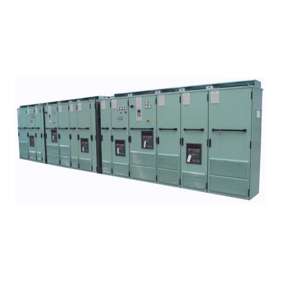
Enclosed converter
Hide thumbs
Also See for DCS800 Series:
- Service manual (158 pages) ,
- Hardware manual (134 pages) ,
- Installation and start-up manual (66 pages)
Table of Contents
Advertisement
Quick Links
Advertisement
Table of Contents

Related Manuals for ABB DCS800 Series


Summary of Contents for ABB DCS800 Series
- Page 1 DCS800 Installation Manual DCS800-A Enclosed Converters (18 to 9800 A / 19600 A)
- Page 2 DCS800 Drive Manuals Language Public. number DCS800 Quick Guide 3ADW000191 DCS800 Tools & Documentation CD 3ADW000211 DCS800 Converter module Flyer DCS800 3ADW000190 Technical Catalogue DCS800 3ADW000192 Hardware Manual DCS800 3ADW000194 Hardware Manual DCS800 update DCF503B/DCF504B 3ADW000194Z0301 Firmware Manual DCS800 3ADW000193 Installation according to EMC 3ADW000032 Technical Guide...
- Page 3 DCS800-A Enclosed Converters 18 to 9800 A / 19600 A Installation Manual Code: 3ADW000352R0101 Rev.: A DCS800-A Installation Manual e a.DOC EFFECTIVE: January 2 , 2009 SUPERSEDES: none ©2009 ABB Automation Products GmbH. All rights reserved.
-
Page 4: Safety Instructions
Safety Instructions What this chapter contains This chapter contains the safety instructions you must follow when installing, operating and servicing the drive. If ignored, physical injury or death may follow, or damage may occur to the drive, the motor or driven equipment. Read the safety instructions before you work on the unit. -
Page 5: Installation And Maintenance Work
Installation and maintenance work These warnings are intended for all who work on the drive, motor cable or motor. Ignoring the instructions can cause physical injury or death and/or damage to the equipment. WARNING! • Only qualified electricians are allowed to install and maintain the drive! •... -
Page 6: Grounding
Grounding These instructions are intended for all who are responsible for the grounding of the drive. Incorrect grounding can cause physical injury, death and/or equipment malfunction and increase electromagnetic interference. WARNING! • Ground the drive, motor and adjoining equipment to ensure personnel safety in all circumstances, and to reduce electromagnetic emission and pick-up. - Page 7 Wear a grounding wrist band when handling the boards. Do not touch the boards unnecessarily. Use grounding strip: ABB order no.: 3ADV050035P0001 WARNING! Handle the fiber optic cables with care. When unplugging optic cables, always grab the connector, not the cable itself. Do not touch the ends of the fibers with bare hands as the fiber is extremely sensitive to dirt.
-
Page 8: Mechanical Installation
Mechanical installation These notes are intended for all who install the drive. Handle the unit carefully to avoid damage and injury. WARNING! • DCS800 sizes D4 ... D7: The drive is heavy. Do not lift it alone. Do not lift the unit by the front cover. Place units D4 and D5 only on its back. -
Page 9: Operation
Operation These warnings are intended for all who plan the operation of the drive or operate the drive. Ignoring the instructions can cause physical injury or death and/or damage to the equipment. WARNING! • Before adjusting the drive and putting it into service, make sure that the motor and all driven equipment are suitable for operation throughout the speed range provided by the drive. - Page 10 Note: • When the control location is not set to Local (L not shown in the status row of the display), the stop key on the control panel will not stop the drive. To stop the drive using the control panel, press the LOC/REM key and then the stop key Safety Instructions 3ADW000352R0101 DCS800-A Installation Manual e a...
-
Page 11: Emc Standards
For more information see DCS800 Hardware Manual (3ADW000194). Conformity Procedure The conformity procedure is a matter of responsibility of the machine manufacturers or the plant builders and of ABB Automation Products corresponding to their share of the extension of the electrical equipment! EMC Standards... -
Page 12: Important Instructions For Plants With Line Filters
Important instructions for plants with line filters Filter in a grounded line (earthed TN or TT network): The filters are suitable for grounded lines only, for example in public European 400 V lines. According to EN 61800-3 filters are not needed in insulated industrial lines with own supply transformers. -
Page 13: Table Of Contents
Table of contents Safety Instructions What this chapter contains ....................4 To which products this chapter applies ................4 Usage of warnings and notes ..................4 Installation and maintenance work ..................5 Grounding ........................6 Mechanical installation ....................8 Operation.........................9 EMC Standards EMC requirements for plants and machines in the EU..........11 Conformity Procedure....................11 Important instructions for plants with line filters.............12 Introduction to this manual... - Page 14 Relay Cable........................ 45 Control Panel Cable ....................45 Optical Cables ......................45 Fieldbus Cables......................45 Connection example in accordance with EMC............46 Cross-sectional areas -Tightening torques..............48 Cable Connections ....................... 52 Mains Cable Connection .................... 52 Low Power Supply...................... 52 High Power Supply.....................
-
Page 15: Introduction To This Manual
Introduction to this manual How to use this manual This Installation Manual about DCS800-A Enclosed Converters is to be used together with the associated publications. Note: If it is not mentioned explicitly all details given in this Installation Manual will be valid for DCS800-A Enclosed Converters. -
Page 16: Inquiries
Inquiries For inquiries about the product please address your local ABB representative, quoting type code and serial number of the unit. If the local ABB representative is not available, inquiries should be addressed to ABB Automation Products GmbH, Ladenburg in Germany. -
Page 17: Mechanical Installation
Mechanical Installation This chapter provides instructions for moving shipping splits (= complete drive systems divided into parts before shipping), fastening them to the floor and joining them together. See DCS800 Technical Catalogue (3ADW000192) and DCS800 Hardware Manual (3ADW000194) for allowed operating conditions of the DC thyristor power converters. -
Page 18: Moving Of The Shipping Splits
Cabinet door opening angle Marine applications including handles and locking devices for open doors Moving of the Shipping Splits Use the steel lifting lugs attached to the top of the cabinets. Insert the lifting ropes or slings into the holes of the lifting lugs. The lifting lugs can be removed (but not mandatory) once the cabinets are in their final position. - Page 19 The center of gravity may be quite high, therefore caution should be used when transporting the shipping splits. Tilting of the cabinets must be avoided. Moving of the shipping splits only with the cabinets in upright position. Note: The shipping split has to be placed on a suitable pallet for transportation by forklift! By fork-lift Remove the bottom wooden frame which is part...
-
Page 20: Working Order Of The Mechanical Installation
The cabinets can be moved to their final position by using an iron bar and a piece of wood at the bottom edge of the cabinet. Take care and place the piece of wood properly to prevent damage the cabinet frame. Final placement of shipping split (Not allowed for marine versions) Working Order of the Mechanical Installation ①... - Page 21 ② Remove the lifting bars (if used) and the lifting lugs (only for marine applications). Refasten the 500 mm from ceiling original bolts or upper vibration dampers (only for marine applications) in order to maintain the degree of protection of the cabinet. ③...
-
Page 22: Fastening The Shipping Split To The Floor
Fastening the Shipping Split to the Floor Shipping Split to the Fastening the shipping split to the floor is especially important in installations subject to vibration or other movement. Insert the clamp into the longitudinal hole in the Fastening Clamps 3AFE 64347683: edge of the cabinet's frame body and fasten it with a bolt to the floor. -
Page 23: Holes Inside The Cabinet
Holes inside the cabinet The cabinet can be fastened to the floor using the fastening holes inside the cabinet, if they are available and accessible. Allowed maximum distance between the fastening points is 800 mm. Fastening holes inside the cabinet Side plates of the cabinet: 15 mm Back plate of the cabinet: 10 mm Small gap between the 200 mm, 400 mm, 600... - Page 24 Ø 31 Ø 18.5 Mounting and through holes Mechanical Installation 3ADW000352R0101 DCS800-A Installation Manual e a...
-
Page 25: Layout Of Bottom Plates
Layout of bottom plates Cabinet 200 mm width, 600 mm depth Mechanical Installation 3ADW000352R0101 DCS800-A Installation Manual e a... - Page 26 Cabinet 400 mm width, 600 mm depth Mechanical Installation 3ADW000352R0101 DCS800-A Installation Manual e a...
- Page 27 Cabinet and incoming 600 mm width, 600 mm depth Mechanical Installation 3ADW000352R0101 DCS800-A Installation Manual e a...
- Page 28 Cabinet and incoming 800 mm width, 600 mm depth Mechanical Installation 3ADW000352R0101 DCS800-A Installation Manual e a...
- Page 29 176.5 D6 cabinet 600 mm width, 600 mm depth Mechanical Installation 3ADW000352R0101 DCS800-A Installation Manual e a...
- Page 30 D6 / D7 cabinet 600 mm width, 600 mm depth Mechanical Installation 3ADW000352R0101 DCS800-A Installation Manual e a...
- Page 31 D6 / D7 cabinet 800 mm width, 600 mm depth Mechanical Installation 3ADW000352R0101 DCS800-A Installation Manual e a...
- Page 32 D7 cabinet 1500 mm width, 600 mm depth Mechanical Installation 3ADW000352R0101 DCS800-A Installation Manual e a...
- Page 33 Depending on the amount of cables several EMC-cable entry plates can be fastened over the cutout of the bottom plates. See also chapter Cable Connections. Note: EMC-cable entry is only required for DCS800-A, when screened cables are used. EMC-cable entry Mechanical Installation 3ADW000352R0101 DCS800-A Installation Manual e a...
-
Page 34: Cable Conduit Below The Cabinet
Cable Conduit below the Cabinet A cable conduit can be constructed below the 400 mm wide middle part of the cabinet. The cabinet weight has to be carried by the two 100 mm wide transverse sections of the floor. Top and side view Prevent the cooling air flow from the cable conduit to the cabinet by using bottom plates. -
Page 35: Vibration Dampers (Marine Versions)
Vibration Dampers (Marine Versions) The shipping split must be fastened to the floor and roof/wall in marine versions as follows: ① Fasten the shipping split to the floor with M10 or M12 bolts through the holes in the vibration damper flat bar. ②... -
Page 36: Joining The Shipping Splits
Joining the Shipping Splits Shipping splits are joined in the busbar joining cabinet. Special distance bolts (M6) for fastening the cabinets together are enclosed in a plastic bag inside a cabinet of the shipping split. The blind rivet nuts are already installed in the post. Detailed view Working order Overview... - Page 37 1. Fasten the front post of the joining section with six distance bolts to the front frame post of the next cabinet. 2. 200 mm wide joining cabinet: Remove the intermediate plate, hiding the back posts in the joining section. Partitioning plate Busbar joining cabinet...
-
Page 38: Connecting The Ac Busbar And The Pe Busbar
Connecting the AC busbar and the PE busbar The horizontal main AC busbars and the PE busbar are connected by access from the front of the 200 mm wide busbar joining cabinet. All necessary materials are located in the joining cabinet. 1. -
Page 39: Filter And Ventilation
Ventilation cov- er with mount- ing hooks Filter Door mounted filter Replacement filters and brass screens can be ordered from ABB: Cabinet width (mm) Filter (Air-Tex G-150) Brass screen 3AFE 1003 3616 3AFE 6152 5718... -
Page 40: Air Duct Outlet For Enclosed Converters With D6 / D7 Modules
Air Duct Outlet for Enclosed Converters with D6 / D7 Modules Converter modules size D6 / D7 installed in Air duct outlet cabinets DCS800-A produce a considerable amount of power loss to be removed by air Air duct cooling. In most cases the switch room is not capable to absorb the heated air. - Page 41 Air baffle plates D4 air baffle plate D7 air baffle plate Attention: Before starting the air baffle plates of the converter modules have to be mounted properly! Mechanical Installation 3ADW000352R0101 DCS800-A Installation Manual e a...
-
Page 42: Electrical Installation
Electrical Installation WARNING! The electrical installation described in this chapter should only be carried out by a qualified electrician. The Safety Instructions at the beginning of this manual must be followed. Negligence of these instructions can cause injury or death. Attention: Additional information about this chapter especially regarding EMC can be found in the manual Technical Guide (3ADW000163). -
Page 43: Cabling Instructions
Cabling Instructions Power Cables The mains and motor cables must be dimensioned according to local regulations and: 1.) to carry the DCS800-A load current. 2.) for at least 60°C (140°F). 3.) to fulfill short-circuit protection. 4.) the inductance and impedance of the cable must be rated according permissible touch voltage appearing under fault conditions (so that the fault point voltage will not rise too high when an earth fault occurs). - Page 44 Connection of a cable screen with the aid of metal clamp to the metal surface of the PCB carrier at a DCS converter Size D6, D7 Screen connection D6 / D7 grounding of cable screens A double shielded twisted pair cable (see Twisted pair cables a), e.g.
-
Page 45: Co-Axial Cables
ABB. Control Panel Cable The cable connecting the DCS800 Control Panel to the DCS800 converter module must not exceed 3 meters. The cable type tested and approved by ABB is included in the DCS800 Control Panel option kits. Optical Cables The max. -
Page 46: Connection Example In Accordance With Emc
Connection example in accordance with EMC Mounting plate Filter Field supply unit Mounting plate with PE DC motor terminals on the busbar and terminals CON-x board lower edge of the PCB carrier Armature and field A1 A2 cables with screens for "first environment"... - Page 47 Important hint: The example shows the principle structure of a DC drive and its connections. It is not a binding recommendation, and it cannot respect all conditions of a plant. Therefore each drive must be considered separately and with respect to the special application.
-
Page 48: Cross-Sectional Areas -Tightening Torques
Cross-sectional areas -Tightening torques Recommended cross-sectional area to DINVDE 0276-1000 and DINVDE 0100- 540 (PE) trefoil arrangement. Recommended cross-sectional areas for AC-connection. Unit type AC - connection (U, V, W) + PE Size Amount of single Amount of holes per phase for Size of UL as per Nema 2 (3*): cores and cross -... - Page 49 9 * 240² DCA63u-4000-0x-D 4000 12 * 240² (1*) Recommended by ABB: (2*) Tightening torque: (3*) Diameter of all holes: 14 mm - Use cable type VPE (90°C; 194°F) with 4 cores M10 = 25 Nm; 18.5 ft. - lbs.
- Page 50 Recommended cross-sectional areas for DC-connection Unit type DC - connection (U+, U-) + 2 * PE Size With DC - fuses Without DC - fuses Amount of single Amount of Size of Amount of holes for Size of UL as per Nema 2 (3*): cores and cross - holes for screws (2*)
- Page 51 11 * 185² DCS800-A0x-4000-12-D 3800 12 * 240² (1*) Recommendation by ABB: (2*) Tightening torque: (3*) Diameter of all holes: 14 mm - Use cable type VPE (90°C; 194°F) with 4 cores M10 = 25 Nm; 18.5 ft. - lbs.
-
Page 52: Cable Connections
Cable Connections WARNING! Make sure that the DCS800-A Enclosed Converter is disconnected from the mains network during installation and that the capacitors of the line filters are discharged. Mains Cable Connection This section describes the mains connections of the DCS800-A enclosed converters. - Page 53 Note: The paint should be removed to allow a good connection to the cabinet frames throughout the whole perimeter of the metal conduit (or a bus duct). The metal conduit (or the bus duct metal) should be electrically continuous throughout its complete length.
-
Page 54: Motor Cable Connection
Concentric shield High-current single-core cable connection Motor Cable Connection Motor cable connection should be performed as indicated in the manual Technical Guide (3ADW000163). Cable Tray or Bus Duct Current de-rating of the cables is required when installing the cables in a cable tray or bus duct. -
Page 55: Motor Cable Connection
Motor Cable Connection Conductive Sleeves Conductive sleeves are supplied by ABB as option to provide 360° high frequency grounding for motor cables. Follow these instructions: 1) Pull cable into the cabinet through the conductive sleeve. 2) If a rubber grommet is used, slide it over the cable. -
Page 56: Control Cable Connection
Connection example in accordance with EMC. EMC Grounding at the Cable Entry 360° high frequency grounding of the control cable screen at the cable entry is available as an option from ABB (see Conductive cushions). Side view Top view Conductive cushions... - Page 57 View from below Thinnest cable Thickest cable Lead-through plate Bottom and Top Entry Proceed as follows: 1) Loosen the lead-through plate position screws. Pull the two parts apart. 2) Bottom entry Lead the cable inside the cabinet through the conductive cushions. Top entry Lead the cable inside the cabinet through the grommet and the conductive cushions.
- Page 58 Stripped cable Conductive surface of the Stripped part covered with screen exposed copper foil Cable screen − Cut the screen at the midpoint of the bare part. Be careful not to cut the conductors. − Turn the screen inside out to expose its conductive surface. −...
-
Page 59: Routing The Cables
Routing the Cables The cables that are sources of interference have to be separated from the cables that are sensitive to interference, thus follows: Distances between different cable types 1. Route the motor cables (DC) away from all other cables. 2. - Page 60 24 VDC 115 / 230 VAC 24 VDC 115 / 230 VAC Not allowed unless the 24 VDC cable is Route 24 VAC and 115 / 230 VDC insulated for 230 VAC or insulated with control cables in separate ducts inside an insulation sleeve for 115 / 230 VAC.
- Page 61 6. Ground the cable screens also at the cable entry. L1 L2 L3 short pigtail Conductive sleeve Unpainted EMC-cable entry plateEMV Unpainted bottom plate Cable mains mot cab farad.dsf Continuity of farady cage Mains- and motor cables Twist the pairs up to the terminals Short pigtail Cable...
- Page 62 7. Avoid long parallel runs of motor cables with other cables in order to decrease electromagnetic interference caused by the rapid changes in the drive output current. 8. Where control cables must cross mains- or motor cables make sure they are arranged at an angle as near to 90 degrees as possible.
-
Page 63: Finger Protection
Finger protection The finger protection is needed to prevent commissioning and service personnel from touching high voltage parts of the drives by mistake. Finger protection DCS800-A module size D7 finger protection WARNING: Before starting the finger protection covers of the DCS800-A enclosed converter have to be mounted properly! Electrical Installation 3ADW000352R0101 DCS800-A Installation Manual e a... -
Page 64: Installation Checklist
Installation Checklist The mechanical and electrical installation of the DCS800-A should be checked before start-up. It is advisable to go through the checklist below together with another person. Study carefully the Safety Instructions at the beginning of this manual before attempting any work on, or with, the unit. Installation Checklist MECHANICAL INSTALLATION (see chapter Mechanical... - Page 65 The connections L+, L-, F+ and F- at motor and drive are OK. The control connections are OK. If pulse encoder is used, check the encoder cables and correct direction of rotation, see DCS800 Hardware Manual (3ADW000194). PT 100, PTC, Klixon cables: Check that the connections are appropriate for the type of sensor used in the motor.
-
Page 66: Preventive Maintenance
Preventive Maintenance WARNING! Before performing any maintenance the chapter Safety Instructions the beginning of this manual must be followed. Negligence of these instructions can cause injury or death. Recommended regular maintenance The DCS requires very little maintenance if installed in an appropriate environment. -
Page 67: Relays And Electrical Connections
busbars consist of 10 layers of pre-shaped sheet copper. This construction is able to compensate for small changes in length caused by temperature rise when current is flowing. The screw fixings between heatsink and flexible copper busbar have to withstand different types of mechanical stress. Therefore each fixing needs to be checked for correct torque. - Page 68 Screws to be checked: Screws to be checked: Screws to be checked: Screws to be checked (located behind the busbar): Power part of a converter module type D7 Preventive Maintenance 3ADW000352R0101 DCS800-A Installation Manual e a...
- Page 69 Preventive Maintenance 3ADW000352R0101 DCS800-A Installation Manual e a...
- Page 70 Open Rebuild Kits for nearly all existing DC drives 230 … 1,200 V tailor-made solutions for… IP00 BBC PxD BBC SZxD ASEA TYRAK other manufacturers ABB Automation Products Wallstadter Straße 59 68526 Ladenburg • Germany Tel: +49 (0) 62 03-71-0 *352R0101A9060000* Fax: +49 (0) 62 03-71-7609 www.abb.com/motors&drives *352R0101A9060000*...