Table of Contents
Advertisement
Quick Links
Download this manual
See also:
Service Manual
Advertisement
Table of Contents

Related Manuals for Yamaha HTR-6160


Summary of Contents for Yamaha HTR-6160
- Page 1 HTR-6160 AV Receiver OWNER’S MANUAL...
-
Page 2: Important Safety Instructions
IMPORTANT SAFETY INSTRUCTIONS IMPORTANT SAFETY INSTRUCTIONS CAUTION RISK OF ELECTRIC SHOCK DO NOT OPEN CAUTION: TO REDUCE THE RISK OF ELECTRIC SHOCK, DO NOT REMOVE COVER (OR BACK). NO USER-SERVICEABLE PARTS INSIDE. REFER SERVICING TO QUALIFIED SERVICE PERSONNEL. • Explanation of Graphical Symbols The lightning flash with arrowhead symbol, within an equilateral triangle, is intended to alert you to the presence of uninsulated “dangerous voltage”... - Page 3 This product, when installed as indicated in the instructions contained in this manual, meets FCC requirements. Modifications not expressly approved by Yamaha may void your authority, granted by the FCC, to use the product. 2 IMPORTANT: When connecting this product to accessories and/or another product use only high quality shielded cables.
- Page 4 12 Only voltage specified on this unit must be used. Using this unit with a higher voltage than specified is dangerous and may cause fire, damage to this unit, and/or personal injury. Yamaha will not be held responsible for any damage resulting from use of this unit with a voltage other than specified.
-
Page 5: Table Of Contents
INTRODUCTION Features ... 2 Supplied accessories ... 2 Notice ... 3 Getting started ... 4 Quick start guide ... 5 PREPARATION Connections ... 10 Optimizing the speaker setting for your listening room (YPAO) ... 32 Using AUTO SETUP ... 32 BASIC OPERATION Selecting the SCENE templates... -
Page 6: Features
(composite video ↔ S-video ↔ component video → HDMI digital video) capability for monitor out DOCK terminal ◆ DOCK terminal to connect a Yamaha iPod universal dock (such as YDS-10, sold separately) or Bluetooth adapter (such as YBA-10, sold separately). -
Page 7: Notice
– and, most importantly, without affecting your sensitive hearing. Since hearing damage from loud sounds is often undetectable until it is too late, Yamaha and the Electronic Industries Association’s Consumer Electronics Group recommend you to avoid prolonged exposure from excessive volume levels. -
Page 8: Getting Started
GETTING STARTED ■ Installing batteries in the remote control Take off the battery compartment cover. Insert the two supplied batteries (AAA, R03, UM-4) according to the polarity markings (+ and –) on the inside of the battery compartment. Snap the battery compartment cover back into place. -
Page 9: Quick Start Guide
The following steps describe the easiest way to enjoy DVD movie playback in your home theater. See pages 11 to 15 for details of the speaker placement. Front right speaker Video monitor Subwoofer Front left speaker Center speaker DVD player Surround back left Surround left speaker... -
Page 10: Setting Up Speakers
Quick start guide Step 1: Set up your speakers Place your speakers in the room and connect them to this unit. PRE OUT SUBWOOFER 1 jack AUDIO MULTI CH INPUT PRE OUT FRONT (8CH) CENTER SINGLE (PLAY) CD-R (REC) DTV/CBL SB (8CH) SURROUND WOOFER... -
Page 11: Connect Dvd Player And Other Components
• Connecting an external amplifier jack • Connecting a DVD player via analog multi-channel audio connection • Connecting a Yamaha iPod universal dock or Bluetooth adapter • Using the REMOTE IN/OUT jacks • Using the VIDEO AUX jacks on the front panel... -
Page 12: Press Scene 1 Button
SCENE button. The SCENE templates are built combinations of input sources and sound field programs. If you connect a Yamaha product that has capability of the SCENE control signals, this unit can automatically activate the component and start playback. Refer to the instruction manual of the DVD player for further information. -
Page 13: Additional Feature
■ After using this unit... Press K MAIN ZONE ON/OFF to set this unit to the standby mode. This unit is set to the standby mode and consumes a small amount of power in order to receive infrared signals from the remote control. -
Page 14: Connections
CONNECTIONS Rear panel AUDIO (PLAY) CD-R (REC) DTV/CBL DTV/CBL SIRIUS OPTICAL COAXIAL DIGITAL INPUT ANTENNA FRONT B/ZONE B/ FRONT A ZONE 2/PRESENCE EXTRA SP 75Ω UNBAL. REMOTE TRIGGER +12V 15mA MAX. Name 1 XM jack (U.S.A. and Canada models only) SIRIUS jack (U.S.A. -
Page 15: Placing Speakers
The surround back speakers supplement the surround speakers and provide more realistic front-to-back transitions. Subwoofer(s) The use of a subwoofer with a built-in amplifier, such as the Yamaha Active Servo Processing Subwoofer System, is effective not only for reinforcing bass frequencies from any or all channels, but also for reproducing the high fidelity sound of the LFE (low-frequency effect) channel included in Dolby Digital and DTS sources. - Page 16 Connections ■ 6.1-channel speaker layout See page 14 for connection information. We recommend that you also add the presence speakers for the effect sounds of the CINEMA DSP sound field program. See page 13 for details. Speaker indications FL/FR: Front left/right C: Center 30˚...
-
Page 17: Using Presence Speakers
■ Using presence speakers The presence speakers supplement the sound from the front and surround back speakers with extra ambient effects produced by the sound field programs (see page 48). You can adjust the vertical position of dialogues with using the presence speakers (see page 73). -
Page 18: Connecting Speakers
Connections Connecting speakers Be sure to connect the left channel (L), right channel (R), “+” (red) and “–” (black) properly. If the connections are faulty, this unit cannot reproduce the input sources accurately. Caution • Before connecting the speakers, make sure that the AC power plug is disconnected from the AC wall outlet. •... - Page 19 ■ For the 6.1-channel speaker setting Center speaker EXTRA SP terminals (see page 14) AUDIO (PLAY) CD-R (REC) DTV/CBL DTV/CBL OPTICAL COAXIAL DIGITAL INPUT FRONT B/ZONE B/ ZONE 2/PRESENCE FRONT A EXTRA SP TRIGGER 5mA MAX. Right Left Front speakers (FRONT A) ■...
-
Page 20: Connecting The Speaker Cable
Connections ■ Connecting the speaker cable Remove approximately 10 mm (0.4 in) of insulation from the end of each speaker cable and then twist the exposed wires of the cable together to prevent short circuits. 10 mm (0.4 in) Loosen the knob. Red: positive (+) Black: negative (–) Insert one bare wire into the hole on the side... -
Page 21: Information On Jacks And Cable Plugs
Information on jacks and cable plugs Connect one of the type of the audio jack(s) and/or video jack(s) that your input components are equipped with. Audio jacks and cable plugs AUDIO DIGITAL COAXIAL (White) (Red) (Orange) Left and right Coaxial analog audio digital audio cable plugs... -
Page 22: Information On Hdmi
Connections Information on HDMI™ ■ HDMI signal compatibility Audio signals Audio signal Audio signal types formats 2ch Linear 2ch, 32-192 kHz, 16/20/24 bit Multi-ch 8ch, 32-192 kHz, Linear PCM 16/20/24 bit 2/5.1ch, 2.8224 MHz, 1 bit Bitstream Dolby Digital, Bitstream (High Dolby TrueHD, definition audio) Dolby Digital Plus,... -
Page 23: Audio And Video Signal Flow
Audio and video signal flow ■ Audio signal flow Input HDMI AUDIO Digital output Analog output Notes • 2-channel as well as multi-channel PCM, Dolby Digital and DTS signals input at one of the HDMI IN jacks can be output at the HDMI OUT jack only when “S.AUDIO”... -
Page 24: Connecting A Tv Monitor Or Projector
Connections Connecting a TV monitor or projector Connect your TV (or projector) to the HDMI OUT jack, the COMPONENT VIDEO MONITOR OUT jacks, the S VIDEO MONITOR OUT jack or the VIDEO MONITOR OUT jack of this unit. Make sure that this unit and other components are unplugged from the AC wall outlets. -
Page 25: Connecting Other Components
Connecting other components Make sure that this unit and other components are unplugged from the AC wall outlets. Notes • When “VIDEO CONV.” is set to “OFF” (see page 97), be sure to make the same type of video connections as those made for your TV (see page 20). -
Page 26: Connecting A Dvd Recorder, Pvr Or Vcr
Connections ■ Connecting a DVD recorder, PVR or VCR AUDIO (PLAY) CD-R (REC) DTV/CBL DTV/CBL OPTICAL COAXIAL DIGITAL INPUT ANTENNA FRONT B/ZONE B/ ZONE 2/PRESENCE FRONT A ■ Connecting a set-top box Optical out Audio out AUDIO (PLAY) CD-R (REC) DTV/CBL DTV/CBL SIRIUS... -
Page 27: Connecting Audio Components
■ Connecting audio components Notes • To make a digital connection to a component other than the default component assigned to each the DIGITAL INPUT jack, select the corresponding setting for “OPTICAL IN”, or “COAXIAL IN” in “I/O ASSIGNMENT” (see page 93). •... -
Page 28: Connecting An External Amplifier
Connections ■ Connecting an external amplifier This unit has more than enough power for any home use. However, if you want to add more power to the speaker output or if you want to use another amplifier, connect an external amplifier to the PRE OUT jacks. Each PRE OUT jack outputs the same channel signals as the corresponding SPEAKERS terminals. - Page 29 Bluetooth adapter This unit is equipped with the DOCK terminal on the rear panel that allows you to connect a Yamaha iPod universal dock (such as YDS-10, sold separately) or Bluetooth adapter (such as YBA-10 sold separately). Connect a...
- Page 30 SCENE control signals of the components. • If the component connected to the REMOTE OUT jack is not the Yamaha product, set “SCENE IR” in the advanced setup menu to “OFF” (see page 109). Using the VIDEO AUX jacks on the...
- Page 31 If you experience poor reception quality, install an outdoor antenna. Consult the nearest authorized Yamaha dealer or service center about outdoor antennas. • The AM loop antenna should always be connected, even if an outdoor AM antenna is connected to this unit.
-
Page 32: Connecting The Power Cable
Connections Connecting the power cable MONITOR OUT AC OUTLETS SWITCHED 120V 80Hz 100W MAX. TOTAL 0.8A MAX. TOTAL To the AC wall outlet ■ AC OUTLETS (SWITCHED) Use these 2 outlets to supply power to any connected components. Connect the power cable of your other components to these 2 outlets. -
Page 33: Turning This Unit On And Off
Turning this unit on and off ■ Turning on this unit Press K MAIN ZONE ON/OFF (or turn on this unit. The main zone is turned on. • When you turn on this unit, there will be delay for a few seconds before this unit can reproduce sound. -
Page 34: Front Panel Display
Lights up when the adaptive dynamic range control feature is turned on (see page 89). 3 DOCK indicator • Lights up when you station your iPod in a Yamaha iPod universal dock (such as YDS-10, sold separately) connected to the DOCK terminal of this unit (see page 25) and V-AUX is selected as the input source. -
Page 35: Using The Remote Control
D SP A B indicators Light up according to the set of front speakers activated (see page 43). SP A: The FRONT A speakers are activated. SP B: The FRONT B speakers are activated. SP A B: The FRONT A and FRONT B speakers are activated. -
Page 36: Optimizing The Speaker Setting For Your Listening Room (Ypao)
OPTIMIZING THE SPEAKER SETTING FOR YOUR LISTENING ROOM (YPAO) Optimizing the speaker setting for your listening room (YPAO) This unit employs the YPAO (Yamaha Parametric Room Acoustic Optimizer) technology which lets you avoid troublesome listening-based speaker setup and achieves highly accurate sound adjustments automatically. The supplied optimizer microphone collects and this unit analyzes the sound your speakers produce in your actual listening environment. - Page 37 Press 8 l / h to select the desired setting for “EXTRA SP ASSIGN” and then press 8 n. Extra speaker assignment EXTRA SP ASSIGN Selects the function of the speakers connected to the EXTRA SP terminals. Choices: FRONT B, ZONE2, ZONE B, PRESENCE, NONE •...
- Page 38 Optimizing the speaker setting for your listening room (YPAO) Press 8 n to select “START” and then press 8 ENTER to start the setup procedure. The following message appears in the OSD. When this unit starts the automatic setup procedure, loud test tones are output at the speakers.
- Page 39 Press 8 k and then 8 ENTER to display the setup results in detail. AUTO SETUP . RESULT 3/4/0.1 DIST: 14.0/17.0ft LVL : -9.0/+6.5dB > CANCEL [ ]/[ ]:Up/Down [ENTER]:Detail RESULT WIRING FRONT L;;;;;;;OK [ ]/[ ]:Select [ENTER]:Return Press 8 l / h repeatedly to toggle between the setup result displays.
- Page 40 Optimizing the speaker setting for your listening room (YPAO) Press 8 ENTER to confirm your selection. The top “SET MENU” screen appears in the OSD. SET MENU . ;AUTO SETUP ;MANUAL SETUP .A;SIGNAL INFO [ ]/[ ]:Up/Down [ENTER]:Enter Press M MENU to exit from “SET MENU”. If you change speakers, speaker positions, or the layout of your listening environment, run “AUTO SETUP”...
-
Page 41: Selecting The Scene Templates
Selecting the SCENE templates This unit is equipped with 18 preset SCENE templates for various situations of using this unit. As the initial factory setting, the following SCENE templates are assigned to each SCENE button (see page 8): SCENE 1: DVD Viewing SCENE 2: Disc Listening SCENE 3: TV Viewing SCENE 4: Radio Listening... - Page 42 Video games Note When iPod is connected to the Yamaha iPod universal dock or a Bluetooth component is connected to the Bluetooth adapter, this unit plays back the audio sources input at the DOCK terminal. You can create your original SCENE templates by editing the preset SCENE templates. See page 40 for details.
- Page 43 Select this SCENE template when you enjoy SIRIUS Satellite Radio programs. 7ch Enhancer MUSIC ENHANCER Select this SCENE template when you play back music on your iPod stationed in a Yamaha iPod universal dock or 7ch Enhancer Bluetooth component that is connected to the Bluetooth adapter. Straight Select this SCENE template when you enjoy general programs on your TV.
-
Page 44: Creating Your Original Scene Templates
Selecting the SCENE templates Creating your original SCENE templates You can create your original SCENE templates for each SCENE button. You can refer to the preset 18 SCENE templates to create the original SCENE templates. Create an original SCENE Select the desired SCENE template Viewing SCENE template library... -
Page 45: Using The Remote Control For The Scene Feature
Using the remote control for the SCENE feature ■ Controlling the input source components in the SCENE mode You can operate both this unit and the input source component by using the remote control. You must set the appropriate remote control code for each input source in advance (see page 102). -
Page 46: Playback
PLAYBACK Caution Extreme caution should be exercised when you play back CDs encoded in DTS. If you play back a CD encoded in DTS on a DTS-incompatible CD player, you will only hear some unwanted noise that may damage your speakers. Check whether your CD player supports CDs encoded in DTS. -
Page 47: Selecting The Multi Ch Input Component
Before performing the following operations, press 5 AMP on the remote control. Selecting the MULTI CH INPUT component Use this feature to select the component connected to the MULTI CH INPUT jacks (see page 25) as the input source. Rotate the R INPUT selector to select “MULTI CH”... -
Page 48: Selecting Audio Input Jacks (Audio Select)
Playback Before performing the following operations, press 5 AMP on the remote control. Selecting audio input jacks (AUDIO SELECT) This unit comes with a variety of input jacks. Use this feature (audio input jack select) to switch between input jacks when more than one input jack is assigned to the same input source. -
Page 49: Using Your Headphones
Using your headphones Connect a pair of headphones with a stereo analog audio cable plug to the PHONES jack on the front panel. EDIT CATEGORY SPEAKERS SEARCH MODE BAND A/B/C/D/E PRESET/TUNING/CH MEMORY INFO SCENE PROGRAM INPUT PHONES TONE CONTROL STRAIGHT PURE DIRECT AUDIO SELECT STANDBY... -
Page 50: Displaying The Input Source Information
Playback Displaying the input source information You can display the audio and video information of the current input signal. Press 5 AMP and then press M MENU on the remote control. The top “SET MENU” display appears in the OSD. SET MENU . -
Page 51: Using The Sleep Timer
Using the sleep timer Use this feature to automatically set the main zone to the standby mode after a certain amount of time. The sleep timer is useful when you are going to sleep while this unit is playing or recording a source. The sleep timer also automatically turns off any external components connected to the AC OUTLETS (see page 28). -
Page 52: Sound Field Programs
This unit is equipped with a variety of precise digital decoders that allow you to enjoy multi-channel playback from almost any stereo or multi-channel sound source. This unit is also equipped with a Yamaha digital sound field processing (DSP) chip containing several sound field programs which you can use to enhance your playback experience. -
Page 53: For Various Sources
LIVE/CLUB Program This program simulates a live house with a low ceiling and homey atmosphere. A realistic, live sound Cellar Club field features powerful sound as if the listener is in a row in front of a small stage. This is the sound field of a rock music live house in Los Angeles, with approximately 460 seats. The The Roxy Theatre listener’s virtual seat is at the center left of the hall. - Page 54 Sound field programs Program This program is ideal for precisely reproducing the sound design of action and adventure movies. The sound field restrains reverberations but puts emphasis on reproducing a powerful space expanded Adventure widely to the left and right. The reproduced depth is also restrained relatively to ensure the separation between audio channels and the clarity of the sound.
-
Page 55: Enjoying Unprocessed Input Sources (Straight Decoding Mode)
■ Using sound field programs without surround speakers (Virtual CINEMA DSP) Virtual CINEMA DSP allows you to enjoy the CINEMA DSP programs without surround speakers. It creates virtual speakers to reproduce the natural sound field. When you set “SUR. L/R SP” to NONE”... -
Page 56: Using Audio Features
USING AUDIO FEATURES Before performing the following operations, press 5 AMP on the remote control. Adjusting the speaker level You can adjust the output level of each speaker while listening to a music source. This is also possible when playing sources input at the MULTI CH INPUT jacks. Note This operation will override the level adjustments made in “AUTO SETUP”... -
Page 57: Fm/Am Tuning
Overview You can use two tuning modes to tune into the desired FM/AM station: Frequency tuning mode (AUTO TUNING/MANUAL TUNING) You can search or specify the frequency of the desired FM/AM station automatically or manually (see “Basic tuning operations” on this page). Preset tuning mode (PRESET TUNING) You can preset the desired FM/AM station in advance, and then recall the station by specifying the preset group and number (see “Using station preset feature”... -
Page 58: Using Station Preset Feature
FM/AM tuning • When this unit is tuned into a station, the TUNED indicator lights up. • Hold down the button to continue searching when this unit is in the manual tuning mode. • Press G INFO (or A INFO) repeatedly to toggle the frequency information and sound field program information in the front panel. - Page 59 Before performing the following operations, press 4 TUNER on the remote control. ■ Automatic station preset You can use the automatic preset tuning feature to store up to 40 FM stations with strong signals (A1 to E8: 8 preset station numbers in each of the 5 preset station groups) in order.
-
Page 60: Exchanging Preset Stations
FM/AM tuning ■ Exchanging preset stations You can exchange the assignments of two preset stations with each other. The example below describes the procedure to exchange preset station “E1” with “A5”. Before performing the following operations, press 4 TUNER on the remote control. Select preset station “E1”... -
Page 61: Xm Satellite Radio Tuning
XM Satellite Radio tuning XM Radio offers an extraordinary variety of commercial-free music, plus the best in premier sports, news, talk radio, stand-up comedy, children’s and entertainment programming. XM is broadcast in superior digital audio quality from coast to coast. From rock to reggae, from classical to hip hop, XM has something for every music fan. XM Satellite Radio online information For U.S. -
Page 62: Activating Xm Satellite Radio
XM Satellite Radio tuning Activating XM Satellite Radio Once you have installed the XM Mini-Tuner Dock, inserted the XM Mini-Tuner, connected the XM Dock to ® your XM Ready home audio system, and installed the antenna, you are ready to subscribe and begin receiving XM programming. -
Page 63: Preset Search Mode
Before performing the following operations, press 3 XM. ■ All Channel Search mode Press B SEARCH MODE (or M SRCH MODE) repeatedly to select “ALL CH SEARCH”. Press E PRESET/TUNING/CH l / h (or 8 PRESET/CH k / n) repeatedly to search for a channel within all channels. -
Page 64: Setting The Xm Satellite Radio Preset Channels
XM Satellite Radio tuning Before performing the following operations, press 3 XM. Setting the XM Satellite Radio preset channels You can use this feature to store up to 40 XM Satellite Radio channels (A1 to E8: 8 preset channel numbers in each of the 5 preset channel groups). -
Page 65: Displaying The Xm Satellite Radio Information
Before performing the following operations, press 3 XM. Displaying the XM Satellite Radio information You can display the XM Satellite Radio information (such as channel number, channel name, category, artist name, or song title) for the currently selected channel in the front panel display or in the OSD. -
Page 66: Sirius Satellite Radio™ Tuning
SIRIUS SATELLITE RADIO™ TUNING SIRIUS Satellite Radio™ tuning SIRIUS Satellite Radio provides over 130 channels of exclusive entertainment and 100% commercial-free music. Only SIRIUS has more than 65 original music channels, from today’s hits to R&B, oldies, and classical masterpieces. From authentic country and real bluegrass to cool jazz, hot latin, reggae, rock and many more. -
Page 67: Activating Sirius Satellite Radio™ Subscription
Activating SIRIUS Satellite Radio™ subscription Before using the SIRIUS Satellite Radio feature, you need to activate your SIRIUS Satellite Radio subscription. To activate the subscription you need the Sirius ID which is uniquely assigned to the SiriusConnect tuner. Sirius ID is 12-digit number and it appears on the package of the SiriusConnect tuner, on the label of the SiriusConnect tuner, and when you tune into the SIRIUS Satellite Radio... - Page 68 SIRIUS Satellite Radio™ tuning Before performing the following operations, press K SIRIUS on the remote control. ■ All Channel Search mode Press B SEARCH MODE (or M SRCH MODE) repeatedly to select “ALL CH SEARCH”. Press E PRESET/TUNING/CH l / h (or 8 PRESET/CH k / n) repeatedly to search for a channel within all channels.
-
Page 69: Setting The Sirius Satellite Radio™ Preset Channels
Before performing the following operations, press K SIRIUS on the remote control. Setting the SIRIUS Satellite Radio™ preset channels You can use this feature to store up to 40 SIRIUS Satellite Radio channels (A1 to E8: 8 preset channel numbers in each of the 5 preset channel groups). - Page 70 SIRIUS Satellite Radio™ tuning Press 8 k / n repeatedly to select “SIRIUS” and then press 8 ENTER. The following menu screen appears. SIRIUS . INPUT RENAME VOL. TRIM;;;;;0.0dB PARENTAL LOCK [ ]/[ ]:Up/Down [ENTER]:Enter Press 8 n repeatedly to select “PARENTAL LOCK”...
-
Page 71: Displaying The Sirius Satellite Radio™ Information
Before performing the following operations, press K SIRIUS on the remote control. Displaying the SIRIUS Satellite Radio™ information You can display the SIRIUS Satellite Radio information (such as channel number, channel name, category, artist name, composer name, or song title) for the currently selected channel in the front panel display or in the OSD. -
Page 72: Using Ipod
AUDIO OUT (REC) jacks for recording. • Your iPod battery is automatically charged when your iPod is stationed in a Yamaha iPod universal dock connected to the DOCK terminal of this unit as long as this unit is turned on. You can also select whether this unit charges the battery of the stationed iPod or not when this unit is in the standby mode by selecting the “STANDBY CHARGE”... - Page 73 ■ Controlling iPod in the menu browse mode You can perform the advanced operations of your iPod using the supplied remote control with the aid of the OSD of this unit. You can browse the songs stored on your iPod in the OSD.
-
Page 74: Using Bluetooth™ Components
Using Bluetooth™ components You can connect a Yamaha Bluetooth adapter (such as YBA-10, sold separately) to the DOCK terminal of this unit and enjoy the music contents stored in your Bluetooth component (such as a portable music player) without wiring between this unit and the Bluetooth component. -
Page 75: Recording
Recording adjustments and other operations are performed from the recording components. Refer to the operating instructions for those components. Caution The DTS signal is a digital bitstream. Attempting to digitally record the DTS bitstream will result in noise being recorded. Therefore, if you want to use this unit to record sources encoded in DTS, the following considerations and adjustments need to be made. -
Page 76: Advanced Sound Configurations
ADVANCED SOUND CONFIGURATIONS Advanced sound configurations Changing sound field parameter settings You can enjoy good quality sound with the initial factory settings. Although you do not have to change the initial factory settings, you can change some of the parameters to better suit the input source or your listening room. - Page 77 ■ Basic configuration of sound field programs Each sound field program has some parameters defining the characteristics of the program. To customize the selected sound field program, adjust “DSP LEVEL” and/ or “DIALG.LIFT” first, and then try other parameters. To change sound field parameter settings, see page 72 for details. Adjusting the effect sound level of the sound field programs (DSP LEVEL) Sound field programs add effect sounds (DSP effect...
- Page 78 Advanced sound configurations ■ Sound field parameters for the advanced configurations Use the following sound field parameters to customize sound field programs in detail. To change sound field parameter settings, see page 72 for details. Sound field parameter INIT.DLY Initial delay. Presence, surround, and surround back sound field initial delay. Changes the apparent distance from the source sound by adjusting the delay between the direct sound and the P.INIT.DLY first reflection heard by the listener.
- Page 79 Sound field parameter ROOM SIZE Room size. Presence, surround, and surround back room size. Adjusts the apparent size of the surround sound field. The larger the value, the larger the surround sound field becomes. As the P.ROOM SIZE sound is repeatedly reflected around a room, the larger the hall is, the longer the time between S.ROOM SIZE the original reflected sound and the subsequent reflections.
- Page 80 Advanced sound configurations Sound field parameter REV.TIME Reverberation time. Adjusts the amount of time taken for the dense, subsequent reverberation sound to decay by 60 dB at 1 kHz. This changes the apparent size of the acoustic environment over an extremely wide range. Set a longer reverberation time for “dead” sources and listening room environments, and a shorter time for “live”...
- Page 81 Sound field parameter DIRECT 2-channel stereo direct. Bypasses the decoders and the DSP processors of this unit for pure hi-fi stereo sound when playing 2-channel analog sources. (“2ch Stereo” only) Choices: AUTO, OFF • Select “AUTO” to bypass the decoders, the DSP processors and the tone control circuitry only when “BASS”...
-
Page 82: Selecting Decoders
Advanced sound configurations Selecting decoders ■ Selecting decoders for 2-channel sources (surround decode mode) Use this feature to play back sources with selected decoders. You can play back 2-channel sources on multi- channels. Press 5 AMP and then Q SUR. DECODE repeatedly on the remote control to select the desired surround decoder. - Page 83 Decoder parameter descriptions Decoder parameter PANORAMA Pro Logic IIx Music and Pro Logic II Music panorama. Sends stereo signals to the surround speakers as well as the front speakers for a wraparound effect. (“PLIIx Music” and “PLII Music” only) Choices: OFF, ON DIMENSION Pro Logic IIx Music and Pro Logic II Music dimension.
-
Page 84: Customizing This Unit (Manual Setup)
CUSTOMIZING THIS UNIT (MANUAL SETUP) Customizing this unit (MANUAL SETUP) You can use the following parameters in “SET MENU” to adjust a variety of system settings and customize the way this unit operates. Change the initial settings (indicated in bold under each parameter) to reflect the needs of your listening environment. - Page 85 Volume menu 2 VOLUME MENU Parameter ADAPTIVE DRC Selects whether this unit automatically adjusts the dynamic range in conjunction with the volume level or not. ADAPTIVE DSP LEVEL Selects whether this unit adjusts the DSP effect level automatically in conjunction with the volume level or not.
- Page 86 (U.S.A. and Canada models only) START PAIRING Pair the connected Yamaha Bluetooth adapter (such as YBA-10, sold separately) with a Bluetooth component (see page 70). Selects the video source played back in the background of the sources input at the MULTI CH INPUT jacks.
- Page 87 Menu Parameter D)INIT. CONFIG AUDIO SELECT DECODER MODE EXTD SUR. E)HDMI SET S.AUDIO F)ZONE2 SET MAX VOL. INIT. VOL. ■ Signal information SIGNAL INFO Use this feature to check audio and video signal information (see page 46). Customizing this unit (MANUAL SETUP) Functions Designates the default audio input jack select setting for the input sources connected to the DIGITAL INPUT jacks when you turn on the...
-
Page 88: Using Set Menu
Customizing this unit (MANUAL SETUP) Using SET MENU Use the remote control to access and adjust each parameter. • You can change the “SET MENU” parameters while this unit is reproducing sound. • If you press S PARAMETER during the “SET MENU” operation, the “SET MENU”... -
Page 89: Basic Menu
1 BASIC MENU Use this feature to manually adjust the basic speaker settings. Most of the “BASIC MENU” parameters are set automatically when you run the automatic setup. 1 BASIC MENU A)SPEAKER SET B)SP LEVEL C)SP DISTANCE D)TEST TONE [ ]/[ ]: Up/Down Enter [ENTER]:... - Page 90 Customizing this unit (MANUAL SETUP) Measure for the speaker size The woofer section of a speaker is – 16 cm (6.5 in) or larger: large – smaller than 16 cm (6.5 in): small Front speakers FRONT SP A)SPEAKER SET FRONT SP SMALL >LARGE Choice Descriptions...
- Page 91 Bass cross over CROSS OVER Use this feature to select the crossover frequency of all the speakers set to “SML” (or “SMALL”) in “SPEAKER SET” (see page 85). All frequencies below the selected frequency will be sent to the subwoofer(s) or front speakers depending on the setting of “LFE/BASS OUT”...
-
Page 92: Speaker Distance
Customizing this unit (MANUAL SETUP) ■ Speaker distance C)SP DISTANCE Use this feature to manually adjust the distance of each speaker and the delay applied to the respective channel. Ideally, each speaker should be the same distance from the main listening position. However, this is not possible in most home situations. -
Page 93: Volume Menu
2 VOLUME MENU Use this menu to manually adjust the various volume settings. 2 VOLUME MENU ADAPTIVE DRC;;;;OFF ADAPTIVE DSP LEVEL;;;;OFF MUTE TYPE;;;;FULL MAX VOL.;;;;+16.5dB INIT. VOL.;;;;;;OFF Up/Down [ ]/[ ]: [p]/[[]: Select Adaptive dynamic range control ADAPTIVE DRC Use this feature to adjust the dynamic range in conjunction with the volume level. -
Page 94: Sound Menu
Customizing this unit (MANUAL SETUP) 3 SOUND MENU Use this feature to adjust the audio parameters. 3 SOUND MENU A)EQUALIZER B)LFE LEVEL C)DYNAMIC RANGE D)LIPSYNC E)EXTD SUR. Up/Down [ ]/[ ]: Enter [ENTER]: ■ Equalizer A)EQUALIZER Use this feature to select the parametric equalizer or the graphic equalizer. -
Page 95: Dynamic Range
■ Low-frequency effect level B)LFE LEVEL Use this feature to adjust the output level of the LFE (low- frequency effect) channel according to the capacity of your subwoofer or headphones. The LFE channel carries low-frequency special effects which are only added to certain scenes. - Page 96 Customizing this unit (MANUAL SETUP) ■ Audio and video synchronization (lip sync) D)LIPSYNC Use this feature to adjust the audio and video synchronization. D)LIPSYNC HDMI AUTO;;;;;;OFF AUTO;;;;;;;;;---ms (offset;;;---ms) MANUAL;;;;;;;;;0ms [ ]/[ ]: Up/Down Select [p]/[[]: HDMI automatic lip sync mode HDMI AUTO If the connected video monitor is connected to the HDMI OUT jack of this unit and compatible with the automatic audio and video synchronization function (automatic lip...
-
Page 97: Input Menu
4 INPUT MENU Use this menu to adjust the parameters of each input source. 4 INPUT MENU 4 INPUT MENU A) SIRIUS TUNER J) BLUETOOTH E) MD/CD-R M) MULTI CH G) DTV/CBL Up/Down [ ]/[ ]: [ ]/[ ]: [ENTER]: Enter [ENTER]: Input source... - Page 98 Customizing this unit (MANUAL SETUP) Input rename INPUT RENAME Use this feature to change the name of the input source that appears in the OSD and in the front panel display. INPUT RENAME DVR . [p]/[[]: Position Character [ ]/[ ]: Enter [ENTER]: [RETURN]:...
- Page 99 Start pairing START PAIRING Use this feature to start pairing the connected Yamaha Bluetooth adapter (such as YBA-10, sold separately) with your Bluetooth component. For details about the pairing, refer to “Pairing the Bluetooth™ adapter and your Bluetooth™ component” on page 70.
-
Page 100: Option Menu
Customizing this unit (MANUAL SETUP) 5 OPTION MENU Use this menu to adjust the optional system parameters. 5 OPTION MENU A)DISPLAY SET B)VIDEO SET C)MEMORY GUARD D)INIT. CONFIG E)HDMI SET F)ZONE2 SET Up/Down [ ]/[ ]: Enter [ENTER]: ■ Display settings A)DISPLAY SET Note Use “VIDEO”... - Page 101 ■ Video settings B)VIDEO SET Note Use “VIDEO” of “INIT” in “ADVANCED SETUP” to set the parameters in “VIDEO SET” to the factory presets (see page 109). B)VIDEO SET VIDEO CONV.;;;;;;ON [ ]/[ ]: Up/Down Select [p]/[[]: Video conversion VIDEO CONV. Use this feature to set whether to convert the video signals input at the VIDEO, S VIDEO, and COMPONENT VIDEO jacks.
- Page 102 “EXTD SUR.” in “SOUND MENU”. ■ HDMI set E)HDMI SET Use this feature to select the component to play back HDMI audio signals. E)HDMI SET S. AUDIO;;;;HTR-6160 Select [p]/[[]: [ENTER]: Return Support audio S.AUDIO Use this feature to select whether to play back HDMI...
- Page 103 ■ Zone 2 settings F)ZONE2 SET F)ZONE2 SET MAX VOL.;;;+16.5dB INIT. VOL.;;;;;OFF [ ]/[ ]: Up/Down Adjust [p]/[[]: Zone 2 Maximum volume MAX VOL. Use this feature to set the maximum volume level in the Zone 2. Control range: –30.0 dB to +15.0 dB, +16.5 dB Control step: 5.0 dB Notes •...
-
Page 104: Remote Control Features
REMOTE CONTROL FEATURES In addition to controlling this unit, the remote control can also operate other audiovisual components made by Yamaha and other manufacturers. To control your TV or other components, you must set up the appropriate remote control code for each input source (see page 102). -
Page 105: Controlling Other Components
■ Controlling other components Press one of the input selector buttons (4) buttons to control other components. You must set the appropriate remote control code for each input source in advance (see page 102). The following table shows the function of each control button used to control other components assigned to each input selector button. -
Page 106: Setting Remote Control Codes
TUNER Yamaha Note You may not be able to operate your Yamaha component even if a Yamaha remote control code is preset as listed above. In this case, try setting another Yamaha remote control code. While pressing and holding one of the input... -
Page 107: Using Multi-Zone Configuration
Yamaha dealer or service center about the Zone 2 connections that best meet your requirements. • Some Yamaha models are able to connect directly to the REMOTE jacks of this unit. If you own these products, you may not need to use an infrared signal emitter. -
Page 108: Controlling Zone 2
(U.S.A. and Canada models only). • Enjoying music stored on your iPod stationed in a Yamaha iPod universal dock (such as YDS-10 sold separately) connected to the DOCK terminal of this unit when “V-AUX” is selected as the input source (see page 68). - Page 109 Operate the following operations after activating the Zone 2 operation mode. Operating Zone 2 Press R INPUT l / h to select the desired input source while the ZONE2 indicator is flashing in the front panel display. • Select “TUNER” as the input source to use the TUNER features in Zone 2.
-
Page 110: Advanced Setup
ADVANCED SETUP This unit has additional menus that are displayed in the front panel display. The advanced setup menu offers additional operations to adjust and customize the way this unit operates. Change the initial settings (indicated in bold under each parameter) to reflect the needs of your listening environment. - Page 111 ■ Remote control AMP ID Use this feature to set the AMP ID of this unit for remote control recognition. This feature is useful when you operate this unit and the other Yamaha receivers/ amplifiers in the same room separately. Choices: ID1, ID2 •...
- Page 112 Advanced setup See page 106 for the operation of the advanced setup. ■ Remote control XM ID (U.S.A. and Canada models only) Use this feature to set the XM ID of this unit for remote control recognition. Choices: ID1, ID2 •...
- Page 113 SCENE mode. Choices: ON, OFF • Select “ON” when the component connected to the REMOTE OUT jack is the Yamaha component and has the capability of the SCENE control signals. This unit automatically sends the remote control signals to the component.
-
Page 114: Troubleshooting
Play a source whose signals can be reproduced by this unit. Connect HDMI components that support the HDCP copy protection standards. Set “S.AUDIO” to “HTR-6160” in “MANUAL SETUP”. Set “VIDEO CONV.” to “ON” or connect your source components in the same way as you connect your video monitor to this unit. - Page 115 Problem Only the center When playing a monaural source with a speaker outputs sound field program, the source signal is substantial sound. directed to the center channel, and the front and surround speakers output effect sounds. No sound is heard “CENTER SP”...
- Page 116 Troubleshooting Problem A source cannot be The source component is not connected to recorded by a digital the DIGITAL INPUT jacks of this unit. recording component Some components cannot record Dolby connected to the Digital or DTS sources. DIGITAL OUTPUT jack. A source cannot be The source component is not connected to recorded by an analog...
- Page 117 ■ Tuner (FM/AM) Problem FM stereo reception is The characteristics of FM stereo noisy. broadcasts may cause this problem when the transmitter is too far away or the antenna input is poor. There is distortion, and There is multi-path interference. clear reception cannot be obtained even with a good FM antenna.
-
Page 118: Xm Satellite Radio
Troubleshooting ■ XM Satellite Radio If an operation takes longer than usual or an error occurs, one of the following messages may appear in the front panel display. In this case, read the cause and follow the corresponding remedies. Status message CHECK XM TUNER The XM Mini-Tuner is not installed in the XM Mini-Tuner Dock or the XM Mini-... - Page 119 ■ SIRIUS Satellite Radio If an operation takes longer than usual or an error occurs, one of the following messages may appear in the front panel display. In this case, read the cause and follow the corresponding remedies. Status message ANTENNA ERROR The antenna is not connected to the SiriusConnect tuner properly.
- Page 120 This unit detects a problem of the connected Bluetooth adapter. Cause Turn off this unit and reconnect the Yamaha iPod universal dock to the DOCK terminal of this unit. Try resetting your iPod. Only iPod (Click and Wheel), iPod nano, and iPod mini are supported.
-
Page 121: Auto Setup
■ AUTO SETUP Before AUTO SETUP Error message Connect MIC! Optimizer microphone is not connected. Unplug HP! Headphones are connected. Memory Guard! The parameters of this unit are protected. During AUTO SETUP Error message E-1:NO FRONT SP Front L/R channel signals are not detected. E-2:NO SUR SP A surround channel signal is not detected. - Page 122 • If the “ERROR” or “WARNING” screens appears, check the cause of the problem, then run “AUTO SETUP” again. • If a warning message “W-1”, “W-2” or “W-3” appears, corrections are made, but they may not be optimal. • If an error message “E-10” occurs repeatedly, contact a qualified Yamaha service center. Cause Check the speaker connections for proper polarity (+ or –).
-
Page 123: Resetting The System
Use this feature to reset all the parameters of this unit to the initial factory settings. Notes • This procedure completely resets all the parameters of this unit including the “SET MENU” parameters. However, the advanced setup menu parameters will not be initialized. •... -
Page 124: Glossary
GLOSSARY ■ Audio and video synchronization (lip sync) Lip sync, an abbreviation for lip synchronization, is a technical term that involves both a problem and a capability of maintaining audio and video signals synchronized during post-production and transmission. Whereas the audio and video latency requires complex end-user adjustments, HDMI version 1.3 incorporates an automatic audio and video syncing capability that allows devices to perform this synchronization automatically and accurately... -
Page 125: Dolby Surround
■ Dolby Surround Dolby Surround uses a 4-channel analog recording system to reproduce realistic and dynamic sound effects: 2 front left and right channels (stereo), a center channel for dialog (monaural), and a surround channel for special sound effects (monaural). The surround channel reproduces sound within a narrow frequency range. - Page 126 Glossary ■ LFE 0.1 channel This channel reproduces low-frequency signals. The frequency range of this channel is from 20 Hz to 120 Hz. This channel is counted as 0.1 because it only enforces a low-frequency range compared to the full-range reproduced by the other 5/6 channels in Dolby Digital or DTS 5.1/6.1-channel systems.
-
Page 127: Sound Field Program Information
The acoustics in your room could be changed to those of a concert hall, a dance floor, or a room with virtually any size at all. This ability to create sound fields at will is exactly what Yamaha has done with the digital sound field processor. ■ CINEMA DSP... -
Page 128: Specifications
SPECIFICATIONS AUDIO SECTION • Minimum RMS Output Power for Front, Center, Surround, Surround back 1 kHz, 0.7% THD, 8 Ω ... 110 W • Dynamic Power (IHF) Front L/R, 8/6/4/2 Ω ... 135/165/195/240 W • Maximum Output Power [Russia model] Speaker impedance setting: 8 Ω, 1 kHz, 0.7% THD, 4 Ω... - Page 129 GENERAL • Power Supply [U.S.A. and Canada models] ... AC 120 V, 60 Hz [Russia model] ... AC 230 V, 50 Hz • Power Consumption [U.S.A. and Canada models] ... 400 W/500 VA [Russia model] ... 440 W • Standby Power Consumption [U.S.A.
-
Page 130: Index
INDEX ■ Numerics 1 BASIC MENU, Manual setup ... 80 2 VOLUME MENU, Manual setup ... 81 2ch STEREO, Sound field program ... 50 3 SOUND MENU, Manual setup ... 81 4 INPUT MENU, Manual setup ... 82 5 OPTION MENU, Manual setup ... 82 7ch Enhancer, Sound field program ... - Page 131 D)TEST TONE, Basic menu ... 88 Decoder descriptions ... 78 Decoder indicators ... 30 DECODER MODE, Initial configuration ... 98 Decoder mode, Initial configuration ... 98 DECODER MODE, Input menu ... 94 Decoder mode, Input menu ... 94 Decoder selection ... 78 DEVICE OVER, HDMI error message ...
- Page 132 Index ■ Manual delay, Lip sync ... 92 MANUAL SETUP ... 80 Manual setup ... 80 MANUAL TUNING ... 53 Manual tuning mode, FM/AM tuning ... 53 MANUAL, Lip sync ... 92 MAX VOL., Audio settings ... 89 MAX VOL., Zone 2 settings ... 99 Maximum volume ...
- Page 133 SCENE 1 ... 8 SCENE 2 ... 8 SCENE 3 ... 8 SCENE 4 ... 8 SCENE IR code setting, Advanced setup ... 109 SCENE IR, Advanced setup ... 109 SCENE template rename ... 40 Sci-Fi, Sound field program ... 49 Searching..., Bluetooth status message ...
- Page 134 Index ■ YPAO indicator ... 30 ■ Zone 2 ... 103 Zone 2 Initial volume, Zone 2 settings ... 99 Zone 2 Maximum volume, Zone 2 settings ... 99 Zone 2 settings, Option menu ... 99 Zone B ... 43 ZONE2 indicator ...
-
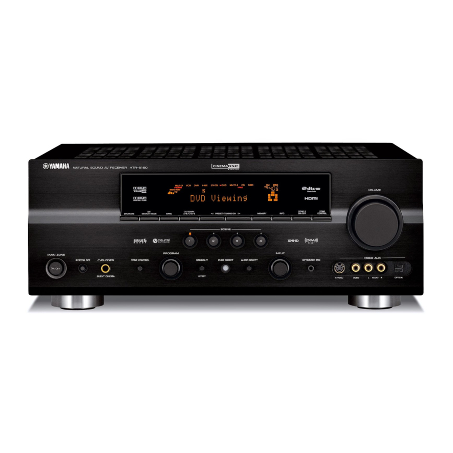
Page 135: Front Panel
■ Front panel SPEAKERS MAIN ZONE PHONES SYSTEM OFF TONE CONTROL ON/OFF SILENT CINEMA EDIT CATEGORY SEARCH MODE BAND A/B/C/D/E PRESET/TUNING/CH MEMORY SCENE PROGRAM STRAIGHT PURE DIRECT AUDIO SELECT EFFECT VOLUME ZONE 2 ZONE INFO ON/OFF CONTROL INPUT VIDEO AUX OPTIMIZER MIC S VIDEO VIDEO... -
Page 136: Remote Control
■ Remote control POWER POWER STANDBY POWER SIRIUS MUTE MD/CD-R TUNER TV CH DTV/CBL V-AUX/DOCK TV VOL TV INPUT TV MUTE SCENE BAND LEVEL SRCH MODE MENU VOLUME TITLE ENTER DISPLAY RETURN MEMORY INFO PROG h ENHANCER SUR. DECODE STRAIGHT PURE DIRECT PARAMETER MULTI CH IN AUDIO SEL SLEEP... -
Page 137: List Of Remote Control Codes
List of remote control codes Blu-ray player Medion Samsung 2137 Micromaxx Micromedia CD player Microstar Yamaha 5000, 5013 Mitsubishi Mizuda CD Recorder Mustek Yamaha 5001 Naiko Onkyo Orava Acoustic Solutions P&B 2078 Pacific Aiwa 2055, 2100 Panasonic Akai 2096 Akura... - Page 138 Akai 0059, 0065, 0127, Cascade 0129, 0130, 0200, Cathay 0204, 0208, 0209, 0213, 0217, 0218, Celebrity 0255 Centurion Akiba 0209, 0218 Century Akura 0206, 0209, 0218 Alaron 0200 Cimline Alba 0200, 0207, 0208, Citizen 0209, 0217, 0218 ALBIRAL 0212 City Allstar 0213 Clarivox...
- Page 139 Lenco 0208 Lenoir 0207, 0208 Lesa 0214 Neckermann Leyco 0206, 0213, 0217 0016, 0038, 0039, 0127, 0128, 0157, Nesco 0158, 0163, 0164, NET-TV 0166, 0188, 0189, New Tech 0200, 0201, 0207, New World 0208, 0210, 0213, Nicamagic 0214, 0215, 0217 Nikkai Liesenk 0217...
- Page 140 Tandy 0127, 0207, 0209, Weltblick 0211, 0218 Weston Tashiko 0200, 0207, 0210 White Westinghouse Tatung 0127, 0204, 0207, 0213, 0217, 0237 Yamaha 0206, 0208 Teac 0127 0207, 0208, 0214, Yamishi 0215 Yoko Techwood 0060, 0061 Teknika 0058, 0060, 0061, 0062...
- Page 141 1010, 1014 1002, 1014, 1021, Weltblick 1045 1027, 1052, 1068, White Westinghouse 1070 1013 1008 XR-1000 1004, 1005, 1006 1007, 1011, 1013, Yamaha 1000, 1001, 1007 1043 Yamishi 1050 1001, 1002, 1014, Yokan 1050 1047 Yoko 1045, 1050 1046 Zenith...
- Page 142 YAMAHA ELECTRONICS (UK) LTD. YAMAHA HOUSE, 200 RICKMANSWORTH ROAD WATFORD, HERTS WD18 7GQ, ENGLAND YAMAHA SCANDINAVIA A.B. J A WETTERGRENS GATA 1, BOX 30053, 400 43 VÄSTRA FRÖLUNDA, SWEDEN YAMAHA MUSIC AUSTRALIA PTY, LTD. 17-33 MARKET ST., SOUTH MELBOURNE, 3205 VIC., AUSTRALIA...
- Page 143 SYSTEM OFF TONE CONTROL ON/OFF SILENT CINEMA EDIT CATEGORY SEARCH MODE BAND A/B/C/D/E PRESET/TUNING/CH SCENE PROGRAM STRAIGHT PURE DIRECT AUDIO SELECT EFFECT ZONE 2 ZONE MEMORY INFO ON/OFF CONTROL INPUT VIDEO AUX OPTIMIZER MIC S VIDEO VIDEO HTR-6160 VOLUME AUDIO OPTICAL...
- Page 144 ■ Remote control POWER POWER STANDBY POWER SIRIUS MD/CD-R TUNER DTV/CBL V-AUX/DOCK TV MUTE TV INPUT SCENE BAND LEVEL SRCH MODE TITLE MENU ENTER DISPLAY RETURN MEMORY INFO PROG h ENHANCER SUR. DECODE STRAIGHT PURE DIRECT PARAMETER MULTI CH IN AUDIO SEL MUTE TV CH TV VOL...