
Related Manuals for HP ProLiant DL320 Generation 3


Summary of Contents for HP ProLiant DL320 Generation 3
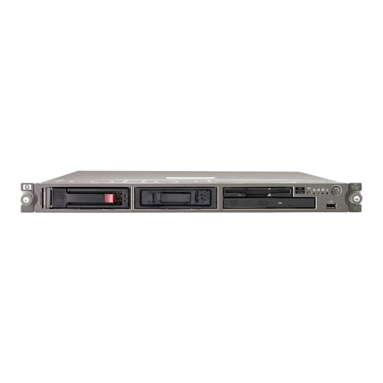
- Page 1 HP ProLiant DL320 Generation 3 Server Maintenance and Service Guide March 2005 (Second Edition) Part Number 373044-002...
- Page 2 The information contained herein is subject to change without notice. The only warranties for HP products and services are set forth in the express warranty statements accompanying such products and services. Nothing herein should be construed as constituting an additional warranty. HP shall not be liable for technical or editorial errors or omissions contained herein.
-
Page 3: Table Of Contents
SATA Hard Drives ..........................2-12 SCSI Hard Drives............................ 2-13 PCI Riser Board Assembly........................2-15 Expansion Board..........................2-16 Single Channel Wide Ultra320 SCSI Adapter.................. 2-17 Integrated SATA RAID Controller Module ..................2-17 HP ProLiant DL320 Generation 3 Server Maintenance and Service Guide... - Page 4 Power Supply .............................5-2 Memory..............................5-3 Optical CD-ROM Drive..........................5-4 Integrated Intel ICH6A SATA Controller ....................5-5 Optional Hard Drives..........................5-5 SATA Hard Drives ..........................5-5 Integrated Broadcom 10/100/1000 Gigabit Server Auto-Switching Network Interface Controller (NIC) 5-6 HP ProLiant DL320 Generation 3 Server Maintenance and Service Guide...
- Page 5 Mechanical and System Spare Parts List .................... 1-4 System Fans ............................2-19 DIMM Socket Identification......................2-26 Rear Panel Components........................4-2 Expansion Slot Component......................... 4-3 System Board Components......................... 4-4 System Switches ..........................4-5 HP ProLiant DL320 Generation 3 Server Maintenance and Service Guide...
- Page 6 SDRAM DIMM Specifications......................5-3 Optical CD-ROM Drive Specifications....................5-4 Intel ICH6A SATA Controller Specifications..................5-5 SATA Hard Drive Specifications......................5-5 Integrated NC7782 10/100/1000 Gigabit Server Auto-Switching NIC Specifications (WOL and PXE capable) ...............................5-6 HP ProLiant DL320 Generation 3 Server Maintenance and Service Guide...
-
Page 7: About This Guide
About This Guide This maintenance and service guide can be used for reference when servicing an HP ProLiant DL320 Generation 3 server. WARNING: To reduce the risk of personal injury from electric shock and hazardous energy levels, only authorized service technicians should attempt to repair this equipment. -
Page 8: Where To Go For Additional Help
For the name of the nearest HP authorized reseller: • In the United States, call 1-800-345-1518. • In Canada, call 1-800-263-5868. • In other locations, refer to the HP website. For HP technical support: viii HP ProLiant DL320 Generation 3 Server Maintenance and Service Guide... - Page 9 If you have purchased a Care Pack (service upgrade), call 1-800-633-3600. For more information about Care Packs, refer to the HP website. Outside North America, call the nearest HP Technical Support Phone Center. For telephone numbers for worldwide Technical Support Centers, refer to the HP website www.hp.com...
-
Page 10: Illustrated Parts Catalog
HP's customer self-repair program offers you the fastest service under either warranty or contract. It enables HP to ship replacement parts directly to you so that you can replace them. Using this program, you can replace parts at your own convenience. -
Page 11: Mechanical Parts Exploded View
Illustrated Parts Catalog Mechanical Parts Exploded View Figure 1-1: Mechanical parts exploded view HP ProLiant DL320 Generation 3 Server Maintenance and Service Guide... -
Page 12: System Components Exploded View
Illustrated Parts Catalog System Components Exploded View Figure 1-2: System components exploded view HP ProLiant DL320 Generation 3 Server Maintenance and Service Guide... -
Page 13: Mechanical Parts And System Components Spares List
SCSI 72-GB U320 HD 289243-001 d) SATA hard drive SATA 80-GB HD 353042-001 SATA 160-GB HD 353043-001 SATA 250-GB HD 353044-001 e) Diskette drive assembly* 390530-001 * Not shown continued HP ProLiant DL320 Generation 3 Server Maintenance and Service Guide... - Page 14 Bezel screws* d) Air baffle e) Pull tab Return kit* 378633-001 Country kit* 378675-001 Option Kit Spares Rack mounting hardware kit* 360104-001 360105-001 Cable management arm Kit* * Not shown HP ProLiant DL320 Generation 3 Server Maintenance and Service Guide...
-
Page 15: Removal And Replacement Procedures
Removal and Replacement Procedures This chapter provides subassembly and module-level removal and replacement procedures for HP ProLiant DL320 Generation 3 Servers. After completing all necessary removal and replacement procedures, run the diagnostics program to verify that all components operate properly. -
Page 16: Symbols On Equipment
The full weight of the rack rests on the leveling jacks. The stabilizers are attached to the rack, if it is a single rack installation. The racks are coupled together in multiple rack installations. HP ProLiant DL320 Generation 3 Server Maintenance and Service Guide... -
Page 17: Server Warnings And Precautions
Removal and Replacement Procedures Use the procedures in this section to perform service events on the ProLiant DL320 G3 Server. HP ProLiant DL320 Generation 3 Server Maintenance and Service Guide... -
Page 18: Powering Down The Server
WARNING: To reduce the risk of personal injury or damage to the equipment, place the server on a sturdy table or workbench whenever it is removed from the rack for device accessibility. Refer to the HP ProLiant DL320 Generation 3 Server User Guide for further information on working with racks. -
Page 19: Access Panel
Off position, auxiliary power is still connected to the PCI expansion slot and may damage the card. CAUTION: ESD can damage electronic components. Ensure proper grounding before beginning any installation procedure. HP ProLiant DL320 Generation 3 Server Maintenance and Service Guide... -
Page 20: Removing The Access Panel
3. Slide the access panel approximately 1.25 cm (0.5 in) toward the rear of the unit and lift the panel to remove it. Figure 2-1: Removing the access panel To replace the access panel, reverse steps 1 through 3. HP ProLiant DL320 Generation 3 Server Maintenance and Service Guide... -
Page 21: Drive Assembly
Reverse steps 1 through 8 to replace the drive assembly. LED/PWR Switch Board To remove the LED/PWR switch board: Power down the server. See “Powering Down the Server” in this chapter. HP ProLiant DL320 Generation 3 Server Maintenance and Service Guide... -
Page 22: Diskette Drive
4. Remove the LED/PWR switch board. See “LED/PWR Switch Board” in this chapter. 5. Remove the 4 screws holding diskette drive (1) and slide the drive out of the assembly (2). HP ProLiant DL320 Generation 3 Server Maintenance and Service Guide... -
Page 23: Optical Drive
Figure 2-4: Remove the diskette drive To replace the diskette drive, reverse steps 1 through 5. NOTE: See the HP ProLiant DL320 Generation 3 Server User Guide for instructions on installing the diskette drive. NOTE: If the diskette drive must be replaced due to failure, the diskette drive cable must be removed from the failed drive and installed on the replacement. -
Page 24: Remove The Optical Drive
Figure 2-5: Remove the Optical drive To replace the optical drive, reverse steps 1 through 4. NOTE: See the HP ProLiant DL320 Generation 3 Server User Guide for instructions on installing the optical drive. NOTE: If the drive must be replaced due to failure, the optical drive backplane must be removed from the failed drive and installed on the replacement. -
Page 25: Hard Drive Overview
The servers include two 1-inch hard drive trays. Hard drives installed in the server are labeled as Device 1 and Device 2 in Figure 2-6 for clarification. IMPORTANT: Always populate hard drive bays starting with the lowest hard drive number. HP ProLiant DL320 Generation 3 Server Maintenance and Service Guide 2-11... -
Page 26: Sata Hard Drives
2. Flip open the tray lever to release the hard drive tray (1), and then slide the tray out of the chassis (2). Figure 2-7: Removing the SATA hard drive tray from the chassis 2-12 HP ProLiant DL320 Generation 3 Server Maintenance and Service Guide... -
Page 27: Scsi Hard Drives
Loosen the thumbscrew that secures the hard drive tray to the chassis (1). Slide the tray toward the front of the server and lift the tray out of the chassis (2). HP ProLiant DL320 Generation 3 Server Maintenance and Service Guide 2-13... -
Page 28: Removing The Scsi Hard Drive Tray From The Chassis
CAUTION: When connecting the power cable to the hard drives, ensure that the connectors are installed so that the red wire faces right when viewed from the front of the server. 2-14 HP ProLiant DL320 Generation 3 Server Maintenance and Service Guide... -
Page 29: Pci Riser Board Assembly
CAUTION: Be careful to remove the large PCI expansion board, if it is present in the assembly, since it is guided and supported with a bracket at its end. When replacing an expansion board, refer to “Expansion Board” following this procedure. HP ProLiant DL320 Generation 3 Server Maintenance and Service Guide 2-15... -
Page 30: Expansion Board
IMPORTANT: Be sure that the expansion board is seated securely in the expansion slot before replacing the PCI riser board assembly and access panel. 2-16 HP ProLiant DL320 Generation 3 Server Maintenance and Service Guide... -
Page 31: Single Channel Wide Ultra320 Scsi Adapter
WARNING: To reduce the risk of personal injury from hot surfaces, allow the internal system components to cool before touching them. 4. Disconnect the fan assembly power cables (1 to 4) from the fan connectors on the system board. HP ProLiant DL320 Generation 3 Server Maintenance and Service Guide 2-17... -
Page 32: Disconnecting The Fan Assembly Power Cables (Processor Heatsink Removed For Clarity)
Reverse steps 1 through 6 to replace the fan assembly. IMPORTANT: See the server hood label or “System Board Connector,” in Chapter 4, “Connectors, Switches, and LED Indicators,” for correct fan cable connections. 2-18 HP ProLiant DL320 Generation 3 Server Maintenance and Service Guide... -
Page 33: Fans
NOTE: Fans are spared and replaced individually. Each fan listed in Table 2-1 is a separate spare. Table 2-1: System Fans Item Component Fan 1 Fan 2 Fan 3 Fan 4 HP ProLiant DL320 Generation 3 Server Maintenance and Service Guide 2-19... -
Page 34: Removing One Fan From The Fan Assembly
Loosen the screws (1) Slide the fan out of the assembly (2). Figure 2-16: Removing one fan from the fan assembly Reverse steps 1 and 2 to replace the fan. 2-20 HP ProLiant DL320 Generation 3 Server Maintenance and Service Guide... -
Page 35: Cables
The hard drive(s) (2) from the backplane c. The power cables (3) (7) d. The diskette drive (5) e. The optical drive (6) Figure 2-17: Disconnecting the SATA cables HP ProLiant DL320 Generation 3 Server Maintenance and Service Guide 2-21... -
Page 36: Disconnecting The Drive Assembly Cables
Removal and Replacement Procedures Figure 2-18: Disconnecting the drive assembly cables Reverse steps 1 through 6 to replace the cables. 2-22 HP ProLiant DL320 Generation 3 Server Maintenance and Service Guide... -
Page 37: Power Supply
Remove the four screws that secure the power supply unit to the chassis (4). Lift the power supply from the server (5). Figure 2-19: Removing the power supply Reverse steps 1 through 6 to replace the power supply. HP ProLiant DL320 Generation 3 Server Maintenance and Service Guide 2-23... -
Page 38: Battery
“PCI Riser Board Assembly” in this chapter. Press the battery release lever away from the battery (2). Lift the battery on the lever side and pull it out of the holder (3). 2-24 HP ProLiant DL320 Generation 3 Server Maintenance and Service Guide... -
Page 39: Locating And Removing The System Battery
Reverse steps 1 through 6 to replace the battery, ensuring that the new battery is installed with the positive side up. HP ProLiant DL320 Generation 3 Server Maintenance and Service Guide 2-25... -
Page 40: Memory Modules
DIMMs installed in the server must be unbuffered DDR1/400, 2.5 volts and 64-bits wide. Do not mix ECC and non-ECC DIMMs or DIMMs of different speeds. If different types of DIMMs are mixed, the system will not function properly. 2-26 HP ProLiant DL320 Generation 3 Server Maintenance and Service Guide... -
Page 41: Removing A Dimm From A Dimm Socket
Removal and Replacement Procedures If only one DIMM is installed, HP recommends installing it in slot 1A. All DIMMs installed must be of the same speed (DDR PC3200). For best performance the amount of memory in bank A should equal to the amount in bank B. -
Page 42: Installing A Dimm In A Dimm Socket
(2). Figure 2-23: Installing a DIMM in a DIMM socket CAUTION: Use only HP supplied DIMMs. DIMMs from other sources can adversely affect data integrity. Press down firmly on the DIMM while pushing the latches inward until the latches snap into place. -
Page 43: Processor
Figure 2-24: Locating the processor on the system board WARNING: To reduce the risk of personal injury from hot surfaces, allow the internal system components to cool before touching them. HP ProLiant DL320 Generation 3 Server Maintenance and Service Guide 2-29... -
Page 44: Loosening Screws On The Heatsink And Removing The Heatsink
6. Remove the heatsink from the top of the processor. 7. Lift the processor locking lever (1) and the cover (2) 8. Lift the processor from the socket (3). 2-30 HP ProLiant DL320 Generation 3 Server Maintenance and Service Guide... -
Page 45: System Board
Disconnect the SATA drive cables. See “Cables” in this chapter. Disconnect the diskette drive cable. See “Cables” in this chapter. 10. Disconnect the optical drive cable. See “Cables” in this chapter. HP ProLiant DL320 Generation 3 Server Maintenance and Service Guide 2-31... -
Page 46: Removing The System Board
13. Remove all screws that secure the system board to the chassis (1). 14. Lift the system board up and away from the standoffs (2). Figure 2-27: Removing the system board Reverse steps 1 through 14 to replace the system board. 2-32 HP ProLiant DL320 Generation 3 Server Maintenance and Service Guide... -
Page 47: Diagnostic Tools
Enabling access to the Array Configuration Utility, Array Diagnostics Utility, and Erase Utility SmartStart is included in the HP ProLiant Essentials Foundation Pack. For more information about SmartStart software, refer to the HP ProLiant Essentials Foundation Pack or the HP website (http://www.hp.com/servers/smartstart). SmartStart Scripting Toolkit The SmartStart Scripting Toolkit is a server deployment product that delivers an unattended automated installation for high-volume server deployments. -
Page 48: Hp Instant Support Enterprise Edition
Configuring memory options Language selection For more information on RBSU, refer to the HP ROM-Based Setup Utility User Guide on the Documentation CD or the HP website (http://www.hp.com/servers/smartstart). NOTE: Enable the SATA SW RAID option under the Advanced Options menu to enable RAID capability for the server. -
Page 49: Rompaq Utility
Integrates with other software maintenance, deployment, and operating system tools Automatically checks for hardware, firmware, and operating system dependencies, and installs only the correct ROM upgrades required by each target server To download the tool and for more information, refer to the HP website (http://h18000.www1.hp.com/support/files/index.html). Integrated Management Log The IML records hundreds of events and stores them in an easy-to-view form. -
Page 50: Integrated Lights-Out Technology
ASR increases server availability by restarting the server within a specified time after a system hang or shutdown. At the same time, the HP SIM console notifies you by sending a message to a designated pager number that ASR has restarted the system. You can disable ASR from the HP SIM console or through RBSU. -
Page 51: Hp Insight Diagnostics
USB device drivers. HP provides support for USB devices before the operating system is loaded through legacy USB support, which is enabled by default in the system ROM. HP hardware supports USB version 1.1 or 2.0, depending on the version of the hardware. - Page 52 Diagnostic Tools For additional security, you can individually disable the front, rear, and internal USB connectors through RBSU. Disabling the rear USB connectors in RBSU disables both rear USB ports. HP ProLiant DL320 Generation 3 Server Maintenance and Service Guide...
-
Page 53: Component Identifications
This chapter contains illustrations and tables identifying and describing components, connectors, switches, and LED indicator locations on the front panel, rear panel, system board, and hard drives for the HP ProLiant DL320 Generation 3 server. HP ProLiant DL320 Generation 3 Server Maintenance and Service Guide... -
Page 54: Rear Panel Components
T-15/T-10 Torx screwdriver PCI-X expansion slot 1, low-profile half-length 64 bit/100 MHz 3.3 V PCI-X expansion slot 2, full-length 64 bit/133 MHz 3.3 V (Optional PCI Express slot 1, x8) HP ProLiant DL320 Generation 3 Server Maintenance and Service Guide... -
Page 55: Expansion Slot Component
Figure 4-2 and Table 4-2 shows the PCI expansion board slot connector and expansion board slot cover. Figure 4-2: Expansion slot component Table 4-2: Expansion Slot Component Item Description PCI riser board assembly PCI-X slot 1 riser connector PCI-X/PCI Express slot 2 riser connector HP ProLiant DL320 Generation 3 Server Maintenance and Service Guide... -
Page 56: System Board Components
DIMM slot 4 (Bank B) NMI button (SW3) Power connector System maintenance switch (SW1) Power connector PCI-X slot 1 riser connector* Fan 1 connector * Designations if the optional PCI riser board is installed. HP ProLiant DL320 Generation 3 Server Maintenance and Service Guide... -
Page 57: System Switches
84/85 and iLO diagnostic LEDs. The use of this switch to control the multiplexer is for debug purposes only. The shipping setting also controls the multiplexer so that the iLO diagnostic LEDs will be on (see Table 4-5). HP ProLiant DL320 Generation 3 Server Maintenance and Service Guide... -
Page 58: Non-Maskable Interrupt Switch (Nmi Button/Sw3)
Front Panel Buttons and LEDs Front panel status LEDs allow constant monitoring of basic system functions while the server is operating. Figure 4-5 and Table 4-6 provide the LED locations and functions. HP ProLiant DL320 Generation 3 Server Maintenance and Service Guide... -
Page 59: Rear Panel Leds
Flashing Green = Drive activity. Off = No drive activity. NOTE: Hard drive LEDs function only when connected to an optional HP smart array PCI storage card. Rear Panel LEDs The server rear panel contains three LEDs that allow monitoring of network activity and server identification. -
Page 60: System Board Leds
The LEDs will stay latched to maintain their information when the system is powered off, with the exception of internal status LEDs. All LEDs will be cleared and restored to normal state after power cycle. HP ProLiant DL320 Generation 3 Server Maintenance and Service Guide... -
Page 61: System Board Status Leds
DIMM 2A Failure LED DIMM 4B Failure LED DIMM 3B Failure LED VRD Failure LED Processor Failure LED Over Temperature LED System Fan Single/Multi Failure LED (not install) Power Supply Power Good LED HP ProLiant DL320 Generation 3 Server Maintenance and Service Guide... -
Page 62: Specifications
Specifications This chapter provides operating and performance specifications for HP ProLiant DL320 Generation 3 server components and optional hardware. HP ProLiant DL320 Generation 3 Server Maintenance and Service Guide... -
Page 63: System Unit
Table 5-2: Power Supply Specifications Item Description Input characteristics Rated input voltage 100 VAC to 240 VAC Rated input line 110 VAC / 220 VAC Frequency range 50 to 60 Hz continued HP ProLiant DL320 Generation 3 Server Maintenance and Service Guide... -
Page 64: Memory
PC3200 ECC unbuffered DDR SDRAM DIMMs Note: DIMMs must be industry-standard 184-pin PC3200 DDR DIMMs. The DDR DIMMs must support CAS Latency 2, or greater. They must also contain the mandatory JEDEC SPD. Use HP supplied DIMMs only. HP ProLiant DL320 Generation 3 Server Maintenance and Service Guide... -
Page 65: Optical Cd-Rom Drive
Type Semiconductor Laser Wave length 795 nm Output power <0.25 mW Operating conditions 5 °C to 55 °C (41 °F to 131 °F) Temperature Humidity 10 % to 80 % HP ProLiant DL320 Generation 3 Server Maintenance and Service Guide... -
Page 66: Integrated Intel Ich6A Sata Controller
100 MBps Single track 0.8 ms Average 9.0 ms Full stroke 17.0 ms Rotational speed 7,200 rpm Bytes/sector Logical blocks 160,086,528 Operating temperature Celsius 5° to 55° Fahrenheit 41° to 131° HP ProLiant DL320 Generation 3 Server Maintenance and Service Guide... -
Page 67: Integrated Broadcom 10/100/1000 Gigabit Server Auto-Switching Network Interface Controller (Nic)
10Base-T/100Base-TX/1000Base-T Ethernet Compatibility IEEE 802.3 Data transfer method 64-bit, 100MHz PCI(X)1.0 Network transfer rate 10/100/1000 Mbps Connector RJ-45 I/O address and interrupt Plug and Play PCI Emissions standards FCC class B HP ProLiant DL320 Generation 3 Server Maintenance and Service Guide... - Page 68 2-24 part number 1-4 specifications 5-4 component-level repairs vii components expansion slot 4-3 installing 2-20 rear panel 4-2 removing 2-20 system board, location 4-4 fan assembly connectors installing 2-18 HP ProLiant DL320 Generation 3 Server Manintenance and Service Guide Index-1...
- Page 69 1-5 power supply 2-23 modes, Cable-Select 2-11 processor 2-31 SATA cables 2-22 SATA hard drives 2-13 SCSI hard drives 2-15 network interface controller (NIC) LEDs, link/activity status 4-8 Index-2 HP ProLiant DL320 Generation 3 Server Manintenance and Service Guide...
- Page 70 1-5 installing 2-17 rack weight, warnings 2-3 removing 2-17 rear panel components 4-2 SmartStart and Software Support CD 2-1 rear panel LEDs 4-7 SmartStart Autorun Menu 3-1 HP ProLiant DL320 Generation 3 Server Manintenance and Service Guide Index-3...
- Page 71 2-24 components 4-4 installing 2-32 ventilation clearances viii part number 1-4 removing 2-31 system board status LED 4-8 system components warranty viii exploded view 1-3 illustrated 1-3 Index-4 HP ProLiant DL320 Generation 3 Server Manintenance and Service Guide...