Table of Contents
Advertisement
Quick Links
Advertisement
Table of Contents

Related Manuals for Yamaha MIXING CONSOLE


Summary of Contents for Yamaha MIXING CONSOLE
- Page 1 Owner’s Manual Keep This Manual For Future Reference.
- Page 2 300 ohm ribbon lead, change the lead-in to coaxial type cable. If these corrective measures do not produce satisfactory results, please contact the local retailer authorized to distribute this type of product. If you can not locate the appropriate retailer, please contact Yamaha Corporation of America, Electronic Service Division, 6600 Orangethorpe Ave, Buena Park, CA 90620 The above statements apply ONLY to those products distributed by Yamaha Corporation of America or its subsidiaries.
-
Page 3: Important Safety Instructions
CA UT I O N RISK OF ELECTRIC SHOCK DO NOT OPEN CAUTION: TO REDUCE THE RISK OF ELECTRIC SHOCK, DO NOT REMOVE COVER (OR BACK). NO USER-SERVICEABLE PARTS INSIDE. REFER SERVICING TO QUALIFIED SERVICE PERSONNEL. The above warning is located on the rear of the unit IMPORTANT SAFETY INSTRUCTIONS Read these instructions. -
Page 4: Important Information
This unit has a slot for installing mini-YGDAI cards. For technical reasons, certain card combinations are not supported. Before installing any cards, check the Yamaha web site to if your card is compatible. Installing cards that are not endorsed by Yamaha may cause elec- trical shock, fire, or damage to the unit. - Page 5 • This unit has ventilation holes along the top, front, rear, and sides to prevent the internal temperature from rising too high. Do not block them. Blocked ventilation holes are a fire hazard. In particular, do not operate the unit while it’s on its side, is upside down, or while it’s covered with a cloth or dust sheet.
-
Page 6: Yamaha Web Site
Avid Technology, Inc. Tascam Digital Interface is a trademark and Tascam and Teac are registered trademarks of Teac Corporation. Microsoft and Windows are registered trademarks of Microsoft Corporation, Inc. Waves is a trademark of Waves, Inc. Yamaha is a trademark of Yamaha Corporation. All other trademarks are the property of their respective holders and are hereby acknowledged. -
Page 7: Conventions Used In This Manual
About this Owner’s Manual This Owner’s Manual explains how to operate the 01V96 Digital Mixing Console. The Table of Contents can help you to familiarize yourself with the manual’s organization and to locate tasks and topics. The index can help you locate specific information. -
Page 8: Table Of Contents
Contents Contents Welcome ..........11 Control Surface &... - Page 9 Setting Aux Send Levels ..........113 Viewing Aux Send Settings for Multiple Channels .
- Page 10 Contents 18 MIDI ..........211 MIDI &...
-
Page 11: Welcome
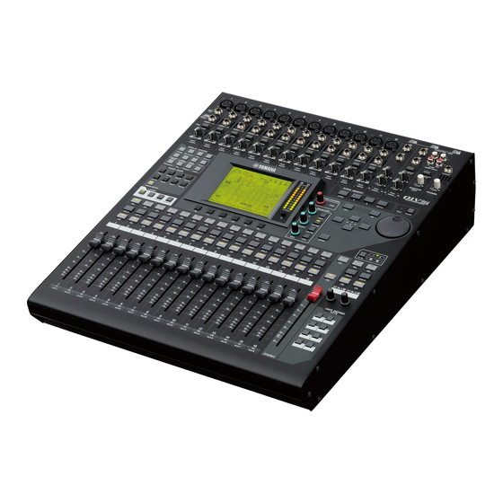
1 Welcome Thank you for choosing the Yamaha 01V96 Digital Mixing Console. The compact 01V96 Digital Console features 24-bit/96 kHz digital audio processing with- out compromise, as well as 40-channel simultaneous mixing. The 01V96 covers a broad range of needs and applications, including multi-track recording, 2-channel mixdown, and cutting-edge surround sound production. -
Page 12: Scene Memory
Chapter 1—Welcome ■ Channel Configuration • 32 Input Channels and four ST IN channels can be mixed at a time. Group multiple channels and pair channels for stereo. • Eight Bus Outs and eight Aux Sends. Bus Outs 1-8 can be routed to Stereo Buses for use as Group Buses. -
Page 13: Control Surface & Rear Panel
2 Control Surface & Rear Panel Control Surface AD Input Section (p. 14) DISPLAY ACCESS Section (p. 18) INPUT (BAL) INSERT OUT IN (UNBAL) INSERT I/O INSERT I/O INSERT I/O INSERT I/O 20dB 20dB 20dB 20dB GAIN GAIN GAIN GAIN PEAK PEAK PEAK... -
Page 14: Ad Input Section
Chapter 2—Control Surface & Rear Panel AD Input Section INPUT (BAL) INSERT OUT IN (UNBAL) INSERT I/O INSERT I/O INSERT I/O 20dB 20dB 20dB GAIN GAIN GAIN PEAK PEAK PEAK SIGNAL SIGNAL SIGNAL A INPUT connectors A/B INPUT A connectors are balanced XLR-3-31-type connectors that accept line-level and microphone signals. -
Page 15: Gain Controls
D PAD switches These switches turn on or off the 20 dB pad (attenuator) for each AD Input. E GAIN controls These controls adjust input sensitivity for each AD Input. Input sensitivity is –16 dB to –60 dB when the Pad is off, and +4 dB to –40 dB when the Pad is on. F PEAK indicators These indicators light up when the input signal level is 3 dB below clipping. - Page 16 Chapter 2—Control Surface & Rear Panel Channel Strip Section A [SEL] buttons These buttons enable you to select desired channels. The [SEL] button indicator for the cur- rently-selected channel lights up. The channel selected by each [SEL] button depends on the layer selected in the LAYER section (see page 19).
-
Page 17: Fader Mode Section
ST IN Section A [ST IN] button This button selects an ST IN channel pair (ST IN Channels 1 & 2 or 3 & 4) which you can control using the buttons and controls in the ST IN section. The indicators to the right of the button indicate the available ST IN channels. -
Page 18: Display Access Section
Chapter 2—Control Surface & Rear Panel DISPLAY ACCESS Section A [SCENE] button This button displays a Scene page, enabling you to store and recall Scenes (see page 161). B [DIO/SETUP] button This button displays a DIO/Setup page, enabling you to set up the 01V96, including digital input and output setup and remote control setup (see pgaes 72, 188). -
Page 19: Display Section
LAYER Section A [1–16]/[17–32] buttons These buttons select an Input Channel layer as the layer controlled in the Channel Strip sec- tion. When the [1–16] button is turned on, you can control Channels 1–16. When the [17–32] button is turned on, you can control Channels 17–32. (See page 31 for more infor- mation on the Input Channel layers.) B [MASTER] button This button selects the Master Layer as the layer controlled in the Channel Strip section. -
Page 20: Selected Channel Section
Chapter 2—Control Surface & Rear Panel E Left Tab Scroll [ F Right Tab Scroll [ If there are more pages available than the four whose tabs are currently displayed, use these buttons to display the additional tabs. These buttons are available only when the left or right Tab Scroll arrow appears. -
Page 21: Scene Memory Section
SCENE MEMORY Section A [STORE] button This button enables you to store the current mix settings. (See page 161 for more informa- tion on Scene Memories.) B Scene Up [ ] / Down [ ] buttons These buttons select a Scene to store or recall. Pressing the Scene Up [ ] button increments the selection;... -
Page 22: Data Entry Section
Chapter 2—Control Surface & Rear Panel Data Entry Section A Parameter wheel This control adjusts the parameter values shown on the display. Turning it clockwise increases the value; turning it counterclockwise decreases the value. This wheel also enables you to scroll a displayed list and select a character for entry (see page 30). B [ENTER] button This button activates a selected (highlighted) button on the display, and confirms the edited parameter values. -
Page 23: Rear Panel
Rear Panel PHANTOM +48V (p. 23) AD Output Section (p. 23) Power Section (p. 25) PHANTOM +48V A CH1–4 ON/OFF switch B CH5–8 ON/OFF switch C CH9–12 ON/OFF switch Each of these switches turns on or off the +48V phantom power feed to four corresponding inputs. -
Page 24: Digital I/O Section
Chapter 2—Control Surface & Rear Panel B OMNI OUT connectors 1–4 These balanced TRS phone-type con- nectors output any Bus signals or channel Direct Out signals. The nom- inal signal level is +4 dB. C STEREO OUT connectors L/R These balanced XLR-3-32-type con- nectors output the Stereo Out signals. -
Page 25: Midi/Control Section
MIDI/Control Section A MIDI IN/THRU/OUT ports These standard MIDI IN, OUT and THRU ports enable you to connect the 01V96 to other MIDI equipment. B TO HOST USB port This USB port enables you to connect a computer equipped with a USB port. SLOT Section A SLOT You can insert optional mini-YGDAI cards into this slot. -
Page 26: Installing An Optional Card
Chapter 2—Control Surface & Rear Panel Installing an Optional Card Visit the following Yamaha Pro Audio web site to ensure that the card you are installing is supported by the 01V96. <http://www.yamahaproaudio.com/>. Follow the steps below to install an optional mini-YGDAI card. -
Page 27: Operating Basics
3 Operating Basics This chapter describes basic operations on the 01V96, including how to use the display and operate the controls on the top panel. About the Display The top panel display indicates various parameters that you must set before you can operate the 01V96. -
Page 28: Selecting Display Pages
Chapter 3—Operating Basics Sampling rate indicator This indicator identifies the 01V96’s current sampling rate: 44.1 kHz (44k), 48 kHz (48k), 88.2 kHz (88k), or 96 kHz (96k). ST IN channel levels These level controls indicate the level of ST IN channels 1–4. Page title This section indicates the title of the current page. -
Page 29: Display Interface
4 Press the cursor buttons to move the cursor (a bold frame) to a button, parameter box, rotary control, or fader so that you can change the value. Tip: The 01V96 remembers the current page and parameter when you select a new page group. If you return to the previous page group, the 01V96 displays the correct page, with the same parameter selected. -
Page 30: Title Edit Window
Chapter 3—Operating Basics Confirmation Messages For certain functions, the 01V96 prompts you for confirmation before executing the func- tions, as shown here. Move the cursor to YES and press [ENTER] to execute the function, or move the cursor to NO and press [ENTER] to cancel. If you take no action for awhile, the confirmation window closes automatically and the function is not executed. -
Page 31: Selecting Layers
Selecting Layers Input Channels and Output Channels (Bus Outs & Aux Outs) are arranged into layers, as illustrated below. There are four layers altogether. Input Channel Layer 1–16 Input Channel Layer 17–32 The currently-selected layer determines the function of the channel strip, [SEL] buttons, [SOLO] buttons, [ON] buttons, and faders. -
Page 32: Selecting Channels
Chapter 3—Operating Basics Selecting Channels To select a channel on the 01V96, press the corresponding [SEL] button. To adjust the Pan and EQ settings, use the rotary controls in the SELECTED CHANNEL section. To select a channel on pages that cover multiple channels, press the corresponding [SEL] but- ton. -
Page 33: Selecting Fader Modes
Selecting Fader Modes The function of channel faders (1–16) depends on the selected Layer and Fader mode. 1 Select a layer that includes the desired channel (see page 31). 2 Press the FADER MODE buttons to select a Fader mode. The button indicators identify the following Fader modes: •... -
Page 34: Metering
Chapter 3—Operating Basics Metering This section describes how to check Input and Output Channel levels using the Meter pages. 1 Press the FADER MODE [HOME] button repeatedly until the Meter | Position page appears. This page enables you to set the metering position for Input and Output Channels. INPUT section This section enables you to select the metering position for Input Channel and ST IN Channel signals. - Page 35 - ST IN page This page displays the left and right ST IN Channel 1–4 levels separately. - Master page This section displays the Output Channel (Aux Out 1–8, Bus Out 1–8, Stereo Out) levels altogether. - Effect page This page displays the internal effects processor 1–4 input and output levels altogether. Metering 01V96—Owner’s Manual...
- Page 36 Chapter 3—Operating Basics - Stereo page This page displays the Stereo Out output level. If you selected the CH1-32 page or the Master page, use the MASTER MODE parameter to select one of the following three metering signal types: • GATE GR... The amount of gain reduction for the gate (only for CH1-32) •...
-
Page 37: Connections And Setup
4 Connections and Setup This chapter explains how to connect and set up your 01V96. Connections The following section explains three typical ways to connect the 01V96 to external equip- ment, although there are numerous others. ■ Configuring an analog 24-channel mixing system Synthesizer MUSIC PRODUCTION SYNTHESIZER Real-time External Control Surface... - Page 38 Chapter 4—Connections and Setup ■ Configuring a recording system with a hard disk recorder HDR (Hard Disk Recorder) Effects processor SLOT INPUT connector OMNI OUT connector Synthesizer MUSIC PRODUCTION SYNTHESIZER Integrated Sampling Sequencer Real-time External Control Sur face Modular Synthesis Plug-in System SONG SCENE INPUT connector INPUT connector...
- Page 39 ■ Configuring a recording system that uses a DAW (Digital Audio Workstation) MIDI interface Audio interface WORD CLOCK OUT MY-16AT etc. Effects processor SLOT INPUT connector INPUT (BAL) INSERT OUT IN (UNBAL) INSERT I/O OMNI OUT connector Synthesizer SCENE / INSERT/ DELAY MUSIC PRODUCTION SYNTHESIZER Real-time External Control Surface...
-
Page 40: Wordclock Connections And Settings
This method of distribution is not recommended for larger systems. Wordclock slave • Star Distribution In this example, a dedicated wordclock distribution box (such as a Yamaha IFU4) is used to supply wordclock signals from the wordclock master to each wordclock slave individually. Wordclock slave 01V96—Owner’s Manual... - Page 41 If the external devices do not have wordclock in and out connectors, you can use the clock information included in the digital audio signals. In this case, digital audio signals and wordclock signals are transferred via the 2TR OUT DIGITAL and 2TR IN DIGITAL jacks or via the digital I/O card installed in the rear panel slot.
- Page 42 Chapter 4—Connections and Setup The source select button indicators are explained below: A usable wordclock signal is present at this input, and it is in sync with the current 01V96 internal clock. No wordclock signal is present at this input. A usable wordclock signal is present at this input, but it is out of sync with the current 01V96 internal clock.
-
Page 43: Input And Output Patching
Input and Output Patching The 01V96 is designed to enable you to patch (assign) signals to Inputs and Outputs. This section explains how to view the signals patched to Inputs and Outputs and change the assignment. Tip: If the data from a connected instrument fails to be input, or if you are unable to monitor the signal at the desired output, check the I/O patching, as explained below: Patching Input Channels By default, the Input Channels are patched as follows:... - Page 44 Chapter 4—Connections and Setup 3 Press [ENTER] to confirm the change. Tip: To restore the default patching, recall Input Patch memory #00 (see page 174). Patching Omni Outs By default, the output connectors are patched as follows: • OMNI OUT connectors 1–4 ...Aux Out 1–4 •...
- Page 45 2 Use the cursor buttons to move the cursor to a patch parameter ( wish to change, and rotate the Parameter wheel or press the [INC]/[DEC] buttons to modify the patching. 3 Press [ENTER] to confirm the change. Tip: To restore the default patching, recall Output Patch memory #00 (see page 175). Input and Output Patching ) you 01V96—Owner’s Manual...
- Page 46 Chapter 4—Connections and Setup 01V96—Owner’s Manual...
-
Page 47: Tutorial
5 Tutorial This chapter describes how to use the 01V96 for multitrack recording and mixdown, using an example in which the 01V96 is connected to a digital multitrack recorder. A rhythm machine, guitar, bass, and keyboard are recorded. Connections and Setup 1 Connect a digital MTR, musical instruments and a microphone to the 01V96. - Page 48 Chapter 5—Tutorial Tip: • See page 40 for more information on wordclock. • See page 75 for more information on 01V96s running at higher sampling frequencies (88.2 kHz or 96 kHz). Note: • You can select the 01V96 internal clock as the wordclock source. In this case, you must set the hard disk recorder so that it will synchronize to an external clock.
-
Page 49: Initial Track Recording
4 Press the [PATCH] button repeatedly until the Patch | Out Patch page appears. On this page, make sure that the Output Patch settings remain set to default values, as shown below. By default (as shown in this example), the signals output from Bus Outs 1–8 are routed to the ADAT OUT connector (Tracks 1–8 of the hard disk recorder in this example), and to the slot output channels (Tracks 9–16 of the hard disk recorder in this example). -
Page 50: Pairing Channels
Chapter 5—Tutorial The CH1-32 page enables you to view Input Channel 1–32 levels and compressor and gate gain reduction amounts. 4 Make sure that the LEVEL button ( tion. The METER MODE section enables you to select the type of signals displayed on the meters. - Page 51 Tip: • You can still select one of the paired channels for control by pressing the corresponding [SEL] button. When you select the channel, the [SEL] button indicator lights up, and the [SEL] button for the paired partner flashes. • You can also determine how to copy the parameter settings to the paired partner by using a special window (see page 226).
- Page 52 Chapter 5—Tutorial • Using Direct Outs Each Input Channel signal is directly routed to and output from the specified output con- nectors and channels. Use this method to patch each Input Channel directly to each MTR track. The following example illustrates the signals directly output from ADAT OUT channels 1–5.
- Page 53 2 Move the cursor to the S button for the Input Channel to which the musical instrument or microphone is connected, then press [ENTER] to turn it off. By default, each Input Channel is routed to the Stereo Bus, which enables you to monitor the signals from the MONITOR OUT connectors and the PHONES jack.
- Page 54 Chapter 5—Tutorial In this example, Input Channel 9–12 signals are routed to ADAT OUT channels 5–8. 8 Press the DISPLAY ACCESS [PAN/ROUTING] button repeatedly until the Pan/Route | Rout1-16 page appears. 9 Move the cursor to the D button for the Input Channels you want to route to Direct Outs, then press [ENTER].
- Page 55 4 Make sure that the S buttons for Input Channels 17–24 are turned on and the 1–8 buttons are turned off, then use the PAN control to pan the moni- toring signal. Tip: Controlling Input Channel 17–32 Pan settings, faders, and the [ON] buttons will affect the monitoring signal, but will not affect the signal recorded to the digital MTR.
- Page 56 Chapter 5—Tutorial EQ’ing the Input Signals The 01V96’s Input Channels feature 4-band full parametric EQ. This section describes how to apply EQ to the signals before they are recorded to the tracks. 1 Press the LAYER [1–16] button. Input Channel Layer 1–16 is now available for control from the channel strip section. 2 Press the [SEL] button for the Input Channel to which you want to apply EQ.
- Page 57 • Q This parameter control specifies the Q (slope) for cut/boost of the center frequency set via the F parameter control. The setting range is between 10 and 0.10. The smaller the value, the steeper the slope becomes. This parameter control also selects the type of EQ for the LOW and HIGH band.
- Page 58 Chapter 5—Tutorial 3 Press the [DYNAMICS] button, then press the [F4] button. The Dynamics | Comp Lib page appears. This page enables you to store compressor settings (programs) to the Compressor library, and recall compressor programs from the library. This example uses one of the compressor programs 1–36 from the Compressor library. 4 Rotate the Parameter wheel to scroll the library title list, and select a pro- gram that you want to recall.
- Page 59 Tip: • The 01V96 features four types of dynamics processors: COMP (Compressor), EXPAND (Expander), COMP. (S) (Compander Soft), and COMP. (H) (Compander Hard). These processors feature different parameters. (See page 278 for the parameters for each compres- sor type.) • You cannot change the compressor type on the Comp Edit page. To change the compressor type, recall a program that uses the desired compressor type from the Compressor library, then adjust the parameters as desired.
-
Page 60: Overdubbing To Other Tracks
Chapter 5—Tutorial Tip: If the digital MTR supports MMC (MIDI Machine Control) commands, you can use the 01V96’s Machine Control function to select tracks or locate a position on the recorder from the 01V96 (see page 208). Overdubbing to Other Tracks This section describes how to overdub the musical instruments or microphone connected to the INPUT connectors 1 and 2 to the digital MTR’s Tracks 9 and 10, while listening to the performance recorded on Tracks 1–8. - Page 61 Routing Signals Follow the steps below to route the Input Channel 1 and 2 signals to Slot Channels 1 and 2 directly so that the signals will be recorded to Tracks 9 and 10 on the digital MTR. 1 Press the DISPLAY ACCESS [PATCH] button repeatedly until the Patch | Direct Out page appears.
- Page 62 Chapter 5—Tutorial 5 Press the [F1] button to display the Pan/Route | Pan page, then use the PAN parameter controls on the page to pan channel signals. 6 Press the DISPLAY ACCESS [HOME] button, then press the [F1] button to dis- play the Meter | CH1-32 page.
-
Page 63: Mixing Recorded Tracks Into Stereo (Mixdown)
Mixing Recorded Tracks into Stereo (Mixdown) “Mixdown” is the process of mixing recorded tracks into stereo and recording the stereo sig- nal to an external master recorder. This section describes how to mix signals recorded on Tracks 1–16 into a stereo signal, then apply the 01V96’s internal effects to the signal, then record it to an external master recorder. - Page 64 Chapter 5—Tutorial 3 Move the cursor to the 2L parameter box in the STEREO INPUT section, rotate the Parameter wheel or press the [INC]/[DEC] buttons to select “2TD L,” then press [ENTER]. 4 In the same way, move the cursor to the 2R parameter box in the STEREO INPUT section, then select “2TD R.”...
- Page 65 Mixing Recorded Tracks into Stereo (Mixdown) Input Channel 17–32 signals input from Tracks 1–16 of the digital MTR are now routed through the Stereo Bus, to the STEREO OUT and 2TR OUT DIGITAL connectors. 5 Use the PAN parameter controls for Input Channels 17–32 on the page to adjust the panpot for each track.
-
Page 66: Using The Internal Effects
Chapter 5—Tutorial Using the Internal Effects The 01V96 features four internal multi-effects processors that can be used via Aux Sends and Returns or by inserting them into specific channels. This section describes how to use internal Effects processor 1 via Aux Send 1, and apply reverb to the track signals. 1 Press the DISPLAY ACCESS [PATCH] button repeatedly until the Patch | Effect page appears. - Page 67 Mixing Recorded Tracks into Stereo (Mixdown) 4 Rotate the Parameter wheel and select “2. Reverb Room” For purposes of this tutorial, select this room reverb program. 5 Move the cursor to the RECALL button located to the left of the list, then press [ENTER].
- Page 68 Chapter 5—Tutorial Recording to the Master Recorder Follow the steps below to record the mixed stereo signal from the 01V96 to the connected master recorder. 1 Start recording on the master recorder, then start playing back on the digital MTR. During recording, observe the stereo meter on the right of the display and confirm that the stereo output level is not clipping.
-
Page 69: Analog I/O & Digital I/O
6 Analog I/O & Digital I/O This chapter describes the 01V96’s analog and digital input/output connectors as well as the basic operations involving the digital I/Os. Analog Inputs & Outputs Input Section The 01V96’s top panel features input connectors, which enable you to connect microphone and line-level sources. -
Page 70: Output Section
Chapter 6—Analog I/O & Digital I/O • GAIN controls GAIN PEAK SIGNAL • PEAK & SIGNAL Indicators GAIN PEAK SIGNAL • 2TR IN connectors -10dBV (UNBAL) Output Section The 01V96 top and rear panels feature output connectors that enable you to connect a mon- itoring system, master recorder, effects processors and other line-level devices. -
Page 71: Digital Inputs & Outputs
Bus Outs or Input Channel Direct outs to this output (page 123). SLOT This slot allows you to install an optional mini-YGDAI (Yamaha General Digital Audio Interface) I/O card. This card offers AD/DA conversion, and various analog I/O options and digital I/O interfaces in all the popular digital audio interconnect formats, including AES/EBU, ADAT, and Tascam. -
Page 72: Converting Sampling Rates Of Signals Received At I/O Card Inputs
2. These cards support 24-bit/96 kHz in Double Channel mode. They require 96kHz wordclock sig- nals. 3. This card is identical to the MY8-AE96, except that it features a sampling rate converter. See the Yamaha Professional Audio Web site at the following URL for up-to-date news on I/O cards: <http://www.yamahaproaudio.com/>. -
Page 73: Monitoring Digital Input Channel Status
2 Use the cursor buttons to move the cursor to any two-channel button in the SRC sections, then press [ENTER]. The sampling rate converter for the selected 2-channel input turns on or off. When on, the sampling rate of the received digital audio is converted to the 01V96’s current sampling rate. Monitoring Digital Input Channel Status You can view and monitor the Channel Status (sampling rate, emphasis, etc.) of digital audio signals connected to the 2TR Digital Inputs and Slot Inputs as follows. -
Page 74: Dithering Digital Outputs
Chapter 6—Analog I/O & Digital I/O Parameter value D.Broadcast Instruments A/D Conv A/D Conv with (C) Solid Memory Experimental Unknown Note: “AES/EBU” appears in the Category row when you are monitoring IEC958 Part 3 (AES/EBU-Professional) format signals (that do not include Category Code Bit). COPY Indicates the status of copy protection information included in the IEC958 Part2 (S/PDIF-Consumer) format signals. -
Page 75: Setting The Transfer Format For Higher Sampling Rates
(i.e., 88.2 kHz or 96 kHz). Select this mode if the devices that support the higher sampling rates transmit or receive data. Note: This mode is available only for the slot in which the optional Yamaha MY8-AE96 or MY8-AE96S Digital I/O card is installed. - Page 76 88.2 kHz. Note: • This mode is unavailable for the slot in which the optional Yamaha MY9-AE96 or MY8-AE96S Digital I/O card is installed. • You cannot select this mode unless the 01V96 is operating at a high sampling rate.
-
Page 77: Input Channels
7 Input Channels This chapter describes how to adjust the 01V96’s Input Channel parameters. About Input Channels The input Channel section enables you to adjust the level and tone of the signals input to the 01V96 (and the signals output from the internal Effects processors 1–4), and route the signals to Buses 1–8, the Stereo Bus, and Aux Sends 1–8. - Page 78 Chapter 7—Input Channels • ON (On/Off) This section enables you to turn the channel on or off. The channel is muted with the Off setting. • LEVEL This section enables you to adjust the input level of the Input Channel signal. •...
-
Page 79: Setting The Input Channels From The Display
Refer to the description of Input Channels for more information on these parameters (page 77). Tip: You can store these channel parameter settings in the Channel library. You can also store the Gate, Compressor, and EQ parameter settings to the corresponding libraries. Setting the Input Channels from the Display To set the Input Channel parameters, you can either move the cursor to the desired param- eter on the display and change the value, or operate the desired button or control on the top... -
Page 80: Delaying Input Channels
Chapter 7—Input Channels Delaying Input Channels To set the delay for each channel, press the [ the page listed below that contains the desired channels appears. - DLY 1-16 page This page enables you to set the Delay function for Input Channels 1–16. - DLY 17-32 page This page enables you to set the Delay function for Input Channels 17–32. -
Page 81: Gating Input Channels
Tip: • This function is unavailable for the ST IN Channels. • The delay time range depends on the sampling rate at which the 01V96 is operating. (For example, at 44.1 kHz, the range is 0 through 984.1 msec.) • If you select the DELAY SCALE meter or feet button, the distance value can be converted to the delay time based on sonic speeds (about 340 m/sec at 15 degrees Celsius). -
Page 82: Compressing Input Channels
Chapter 7—Input Channels Meters These meters indicate the levels of the post-gate signals and the amount of gain reduc- tion. ON/OFF The ON/OFF button turns the currently-selected Input Channel’s gate on or off. PARAMETER These controls enable you to set the gate parameters. (See page 278 for more informa- tion on the parameters.) Tip: •... -
Page 83: Attenuating Input Channels
Meters These meters indicate the levels of the post-compressor signals and the amount of gain reduction. ON/OFF The ON/OFF button turns the currently-selected Input Channel’s compressor on or off. PARAMETER section These controls enable you to set the compressor parameters. (See page 278 for more information on the parameters of each compressor type.) Tip: •... - Page 84 TYPE. TYPE Selects the type of EQ. TYPE I is the EQ type used on legacy Yamaha 02R series digital mixing consoles. TYPE II is a newly developed algorithm. Determines the amount of pre-EQ signal attenuation in dB. It is the same Attenuator parameter that appears on the EQ | ATT In page.
-
Page 85: Panning Input Channels
Tip: • The LOW-band EQ functions as a high-pass filter when the Q parameter in the LOW section is set to HPF. It functions as a shelving-type EQ when the Q parameter is set to L.SHELF. • The HIGH-band EQ functions as a low-pass filter when the Q parameter in the HIGH sec- tion is set to LPF. -
Page 86: Routing Input Channels
Chapter 7—Input Channels Tip: • You can adjust the pan setting for the ST IN Channels L & R separately. • You can also adjust the pan setting for the Input Channels using the PAN control in the SELECTED CHANNEL section. •... -
Page 87: Viewing Input Channel Settings
When this button is turned on, the currently-selected Input Channel is routed to the Stereo Bus. When this button is turned on, the currently-selected Input Channel is routed to its Direct Out. See page 125 for more information on the Direct Out. ALL STEREO This button turns on the S button for all channels on the page. - Page 88 Chapter 7—Input Channels COMP section (*) This section enables you to turn the compressor-type dynamics processor on or off and set the parameters. (See page 82 for more information.) INSERT section (*) This section enables you to turn the Insert on or off and patch the Insert In and Out. (See page 127 for more information.) EQ section This section enables you to set various EQ parameters.
- Page 89 Setting the Input Channels from the Display • ON/OFF button ...This button turns on or off the currently-selected Input Chan- nel. • Fader ...This parameter sets the fader position of the currently-selected Input Channel. The fader knob is highlighted when the fader is set to 0.0 dB.
-
Page 90: Setting The Input Channels From The Control Surface
Chapter 7—Input Channels Setting the Input Channels from the Control Surface You can use the faders, [SEL] buttons, and various buttons and controls in the SELECTED CHANNEL section on the top panel to directly control most parameters for Input Chan- nels. - Page 91 Setting the Input Channels from the Control Surface EQ’ing Input Channels 1 Press the [SEL] button or move the fader for the channel you wish to control. 2 To control EQ for the currently-selected channel, press one of the following buttons to select the band you wish to adjust: •...
-
Page 92: Pairing Input Channels
Chapter 7—Input Channels Pairing Input Channels On the 01V96, you can pair adjacent odd-even Input Channels or counterpart channels on Layer 1 and Layer 2 that share the same physical fader. Faders and most parameters of paired channels are linked for stereo operation. Paired channels’ linked parameters and non-linked parameters (that are available for independent control) are listed below: Linked parameters [SEL] buttons... - Page 93 2 Move the cursor to the desired button in the Channel Pairing window, then press [ENTER]. The following buttons are available in this window: • CANCEL Cancels the operation. • CH x ➔ y Copies the odd channel parameter values to the even channel. •...
-
Page 94: Naming Input Channels
Chapter 7—Input Channels When you switch the Pair Mode, the combinations of channel numbers displayed on the page also change. Note: • When Pair mode is switched, only the channel numbers change. The mix parameters of the paired partners do not change. •... - Page 95 2 Move the cursor to a name you wish to change, then press [ENTER]. The Title Edit window appears, enabling you to enter a name. 3 Edit the name, move the cursor to the OK button, then press [ENTER]. The new name is now effective. Tip: The edited name is stored in the Input Patch library.
- Page 96 Chapter 7—Input Channels 01V96—Owner’s Manual...
-
Page 97: Bus Outs
8 Bus Outs This chapter describes how to adjust the 01V96’s Stereo Out and Bus Out 1–8 parameters. About Stereo Out The Stereo Out section receives Input Channel and Bus Out 1–8 signals, mixes them into two channels, processes them using on-board EQ, compressor, etc., then routes them to the STEREO OUT and 2TR OUT connectors. -
Page 98: Bus Out 1-8
Chapter 8—Bus Outs • METER This section enables you to switch the metering position of signal levels that are displayed on the Meter page or by the stereo meter to the right of the screen. (See page 34 for more information on selecting the metering position.) Note: You can also patch the Stereo Out signals to other output connectors or the I/O card by using the Patch | Out Patch pages. -
Page 99: Setting The Stereo Out And Bus Out 1-8 From The Display
Setting the Stereo Out and Bus Out 1–8 from the Display Setting the Stereo Out and Bus Out 1–8 from the Display To set the Stereo Out and Bus Out 1–8 parameters, you can either move the cursor to the desired parameter on the display and change the value, or operate the desired button or control on the top panel. - Page 100 Chapter 8—Bus Outs Compressing the Stereo Out and Bus Outs To set the Stereo Out and Bus Out 1–8 compressors, press the [DYNAMICS] button, then the [F3] button to display the Dynamics | Comp Edit page, and use the [SEL] buttons to select the Stereo Out or Bus Out 1–8.
- Page 101 Setting the Stereo Out and Bus Out 1–8 from the Display Routing Bus Out 1–8 Signals to the Stereo Bus. You can patch Bus Out 1–8 signals to Outputs and Slots 1/2, as well as to the Stereo Bus. You can adjust the level and pan settings of the signals routed to the Stereo Bus for each bus.
- Page 102 Chapter 8—Bus Outs Viewing the Stereo Out and Bus Out Settings You can view and adjust parameter settings for the currently-selected Stereo Out or Bus Out on the View | Parameter and Fader pages. ■ Viewing the Compressor and EQ Settings To display the View | Parameter page, use the corresponding [SEL] button to select the desired bus, then press the DISPLAY ACCESS [VIEW] button, then press the [F1] button.
- Page 103 Setting the Stereo Out and Bus Out 1–8 from the Display Fader This fader adjusts the Stereo Out output levels, and links with the [STEREO] fader. The fader knob is highlighted when the fader is set to 0.0 dB. • Bus Out (1–8) Fader page ON/OFF This button turns the currently-selected Bus Out (1–8) on or off, and links with the [ON] (9–16) button in the Master layer.
-
Page 104: Setting The Stereo Out And Bus Out 1-8 From The Control Surface
Chapter 8—Bus Outs Setting the Stereo Out and Bus Out 1–8 from the Control Surface You can use the faders, [SEL] buttons, and various buttons and controls in the SELECTED CHANNEL section on the top panel to directly control certain parameters for the Stereo Out and Bus Out 1–8. -
Page 105: Pairing Buses Or Aux Sends
Pairing Buses or Aux Sends You can pair adjacent odd-even (in this order) buses or Aux Sends for stereo operation. Paired bus and Aux Send linked parameters and non-linked parameters (that are available for independent controls) are listed below: Linked parameters [SEL] buttons Fader Channel on/off... -
Page 106: Attenuating Output Signals
Chapter 8—Bus Outs Attenuating Output Signals To attenuate the 01V96’s output signals, display the EQ | Out Att page and adjust the Stereo Out and Bus Out 1–8 attenuators individually. If necessary, you can also select Output and I/O card channels and specify the amount of attenuation. -
Page 107: Naming The Stereo Out And Bus Outs
Naming the Stereo Out and Bus Outs You can change the default Bus names (BUS1, AUX4, STEREO, etc.). It may be convenient to name the buses “Monitor Out” or “Effect Send,” for example, so that you can easily iden- tify the signal type. 1 Press the DISPLAY ACCESS [PATCH] button repeatedly until the Patch | Out Name page appears. - Page 108 Chapter 8—Bus Outs 01V96—Owner’s Manual...
-
Page 109: Aux Outs
9 Aux Outs This chapter describes how to control Aux Out 1–8. Aux Out 1–8 The Aux Out 1–8 section mixes signals routed from the Input Channels to the correspond- ing Aux Sends, processes them using on-board EQ, compressor, etc., then routes them to the specified internal effects processors, output connectors or I/O card connectors. -
Page 110: Setting Aux Out 1-8 From The Display
Chapter 9—Aux Outs Setting Aux Out 1–8 from the Display To set Aux Out 1–8 parameters, you can either move the cursor to the desired parameter on the screen and change the value, or operate the desired button or control on the top panel. This section explains how to set the parameters on the screen. - Page 111 Comp settings To set the Aux Out 1–8 compressors, press the DISPLAY ACCESS [DYNAMICS] button, then press the [F3] button to display the Dynamics | Comp Edit page, then select the desired Aux Out 1–8 by using the corresponding [SEL] buttons. The parameters on this page (and the procedure for setting them) are the same as for Input Channels (see page 82).
-
Page 112: Viewing Aux Out Settings
Chapter 9—Aux Outs Viewing Aux Out Settings You can view and adjust the parameter settings for the currently-selected Aux Out on the View | Parameter and Fader pages. ■ Viewing the Compressor and EQ Settings To display the View | Parameter page, use the corresponding [SEL] button to select the desired Aux Out (1–8), then press the DISPLAY ACCESS [VIEW] button, then press the [F1] button. -
Page 113: Setting Aux Out 1-8 From The Control Surface
Setting Aux Out 1–8 from the Control Surface You can use the faders, [SEL] buttons, and various buttons and controls in the SELECTED CHANNEL section on the top panel to directly control certain parameters for Aux Out 1–8. Setting Levels To set Aux Out 1–8 levels, press the [MASTER] button in the LAYER section to select the Master layer, then move faders 1–8. - Page 114 Chapter 9—Aux Outs • MODE Aux Sends have two operating modes that determine how signals are sent: Fixed (Aux Send levels are fixed); and Variable (Aux Send levels are variable). • GLOBAL The GLOBAL PRE and POST buttons enable you to set all Input Channels for the selected Aux to pre-fader or post-fader simultaneously.
- Page 115 • Variable Mode In this mode, Aux Send levels are variable and the signal source point can be either pre-fader or post-fader. Channel Send level rotary controls and PRE/POST buttons appear on the screen. Tip: You can select Variable or Fixed mode individually for each of the eight Aux. Note: •...
- Page 116 Chapter 9—Aux Outs 5 If you switched to Variable mode in Step 3, the PRE/POST buttons and Send level rotary controls enable you to adjust the signal source points and Send levels. You can turn each Input Channel on or off for the currently-selected Aux Send even in Vari- able mode.
-
Page 117: Viewing Aux Send Settings For Multiple Channels
Viewing Aux Send Settings for Multiple Channels You can view and set parameters for all Aux Send 1–8, including setting levels and Pre/Post parameters. This is convenient when you wish to visually check all Aux Send settings or simultaneously adjust the levels of certain channels routed to Aux 1–8. 1 Press one of the FADER MODE [AUX 1]–[AUX 8] buttons repeatedly until the page listed below that contains the desired channels appears. - Page 118 Chapter 9—Aux Outs 3 If you selected the PRE/POST button in Step 2, move the cursor to the desired Input Channel and Aux intersection, then press the [ENTER] button to change the signal source point. Note: You can switch between Pre and Post only for Aux Sends that are set to Variable mode. The “FIX”...
-
Page 119: Panning Aux Sends
Panning Aux Sends You can pair adjacent odd-even (in this order) Aux Sends for stereo operation. This enables you to pan signals from Input Channels to paired Aux Sends. 1 Pair the desired two Aux Sends. (See page 105 for more information on pair- ing channels.) 2 Use the FADER MODE [AUX 1]–[AUX 8] buttons to select one of the paired Aux Sends. -
Page 120: Copying Channel Fader Positions To Aux Sends
Chapter 9—Aux Outs Copying Channel Fader Positions to Aux Sends While Aux Sends are in Variable mode, you can copy all Input Channel fader positions on one layer to the corresponding Aux Sends. This is convenient when you wish to send to the musicians monitor signals that have the same balance setting as the Stereo Out signals. -
Page 121: Input & Output Patching
10 Input & Output Patching This chapter describes how to patch (assign) signal paths within the 01V96 to its inputs, outputs, and slot channels Input Patching Signals input at INPUT connectors 1–16, ADAT IN connector, 2TR IN DIGITAL connec- tors, and Slot I/O card are patched to Input Channels for use. Patch example: INPUT connector 1 INPUT connector 2... - Page 122 Chapter 10—Input & Output Patching Input Patching Follow the steps below to change the Input Patch. 1 Press the DISPLAY ACCESS [PATCH] button repeatedly until the Patch | In Patch page appears. Inputs, ADAT IN channels, and slot channels that are currently assigned to Input Channels are shown in the parameter boxes ( tors are explained below: Parameter value...
-
Page 123: Output Patching
Output Patching The 01V96’s Stereo Out, Bus Out 1–8, Aux Out 1–8 signals can be patched to any outputs, ADAT OUT output channels, and slot output channels. Patch example: Aux Send 1 Aux Send 2 Aux Send 3 Aux Send 4 Aux Send 5 Aux Send 6 Aux Send 7... - Page 124 Chapter 10—Input & Output Patching Changing the Signal Path to the ADAT OUT Connector, Slot, or OMNI OUT connectors Follow the steps below to change the signal path patched to the ADAT OUT connector, the optional mini-YGDAI card installed in the slot, or the OMNI OUT connectors. 1 Press the DISPLAY ACCESS [PATCH] button repeatedly until the Patch | Out Patch page appears.
-
Page 125: Patching Direct Outs
Patching the 2TR Digital Outputs Follow the steps below to change the signal path patched to the 2TR OUT DIGITAL 1 & 2 connectors. 1 Press the DISPLAY ACCESS [PATCH] button repeatedly until the Patch | 2TR Out page appears. Signals assigned on the Out Patch page can also be assigned on this page. - Page 126 Chapter 10—Input & Output Patching • PRE EQ... Immediately before Input Channel EQ • PRE FADER ... Immediately before Input Channel fader • POST FADER ... Immediately after Input Channel fader 2 Move the cursor to a patch parameter (1–32) you want to change, then rotate the Parameter wheel or press the [INC]/[DEC] buttons to select the destination.
-
Page 127: Insert Patching
Insert Patching The 01V96’s Input Channels and Output Channels (Stereo Out, Bus Out 1–8, Aux Out 1–8) feature independent Insert Ins and Outs. Inputs, outputs, ADAT connector channels, slot channels, and internal effects processor inputs and outputs can be patched to the Output Channel Insert Ins and Outs. - Page 128 Chapter 10—Input & Output Patching INSERT section • ON/OFF ... This button turns the Insert on or off. • OUT ... This parameter enables you to select outputs, ADAT OUT • IN ... This parameter enables you to select inputs, ADAT IN chan- COMP section •...
- Page 129 Viewing and Changing Insert In Patch You can view and also change the items patched to the Insert Ins of all Input Channels (or all Output Channels). This is useful when you wish to find out if multiple channels have the same patch.
- Page 130 Chapter 10—Input & Output Patching 01V96—Owner’s Manual...
-
Page 131: Monitoring
11 Monitoring This chapter explains how to set up monitoring and use the Solo function on the 01V96. Monitor The 01V96 features the stereo signal path to feed the monitors. The monitoring signal source is patched to MONITOR OUT connectors L & R and the PHONES connector. The following diagram illustrates the monitoring signal flow. -
Page 132: Monitor And Solo Setup
Chapter 11—Monitoring Monitor and Solo Setup For monitoring and solo setup, press the DISPLAY ACCESS [DIO/SETUP] button repeat- edly until the DIO/Setup | Monitor page appears. This page contains the following parameters: SOLO This parameter turns the Solo function on or off. By default, it is set to Enabled. MODE This parameter determines how the Solo function works. -
Page 133: Using The Monitor
SOLO TRIM This parameter enables you to trim the level of the Solo signal in the range of –96 dB to +12 dB. SOLO SAFE CHANNEL For Mixdown Solo mode, Input Channels can be configured individually so that they are not muted when other Input Channels are soloed (Solo Safe function). Signals from Input Channels with the SOLO SAFE CHANNEL button turned on are always fed to the Stereo bus, regardless of the channels’... -
Page 134: Using The Solo Function
Chapter 11—Monitoring Using the Solo Function You can solo and monitor Input Channels, Aux Out 1–8, and Bus Out 1–8 using the [SOLO] buttons on the top panel. 1 Press the [DIO/SETUP] button repeatedly until the DIO/Setup | Monitor page appears. -
Page 135: Surround Pan
12 Surround Pan This chapter describes surround panning, which determines how Input Channel signals are panned within and across the stereo field. Using Surround Pan About Surround Pan The Surround Pan function places a sound image within a two-dimensional field using a multi-channel playback system, and pans the image to the front, rear, left, and right in rela- tion to the listening position. -
Page 136: Setting Up And Selecting Surround Pan Modes
Chapter 12—Surround Pan When you select one of these Surround modes, each surround channel signal is output as the Bus Out signal specified on the DIO/Setup | Surr Bus page (see page 138). The following table shows the factory-default Surround Channel to Bus Out assignment in each Surround mode. - Page 137 Setting Up and Selecting Surround Pan Modes 2 Move the cursor to the Surround mode button you want to use. When you move the cursor to one of these buttons, speaker icons appear, indicating a typ- ical listening position and the Surround Channel to Bus Out configuration. •...
- Page 138 Chapter 12—Surround Pan 6 To change the Surround Channel to Bus Out assignment, move the cursor to the SURR/BUS SETUP button, then press [ENTER]. The DIO/Setup | Surr Bus page appears. BUS1–BUS8 These parameters select channels to be assigned to the Bus Outs in 3-1, 5.1, and 6.1 Sur- round modes.
- Page 139 ■ Surround Pan Recording To record surround pan movement to a digital MTR, route the Bus Outs to the ADAT OUT channels or slot output channels that are connected to the digital MTR. The following diagram illustrates an example of recording 5.1 Surround mode signals to a digital MTR.
- Page 140 Chapter 12—Surround Pan ■ Surround Pan Monitoring To monitor surround pan movement, patch the Bus Outs to the analog outputs, to which a monitoring system is connected. The following diagram illustrates an example in which Bus Out 1 & 2 (left and right front channel) signals are output from the STEREO OUT L &...
-
Page 141: Surround Panning
Surround Panning You can set the surround pan parameters for each Input Channel. 1 Make sure that the 01V96 is in any Surround mode except Stereo, then press the [SEL] button of the channel for which you want to set surround pan. 2 Press the DISPLAY ACCESS [PAN/ROUTING] button repeatedly until the Pan/Route | Ch Edit page appears. - Page 142 Chapter 12—Surround Pan This parameter control sets the level of the LFE (Low Frequency Effects) Channel signal routed to the subwoofer, and appears only in 5.1 and 6.1 Surround modes. In 6.1 Surround mode, F and R parameter controls appear. The F parameter control determines how the Front Center signal is fed to the Left and Right channels, and the R parameter control determines how the rear surround signal is fed to the Left and Right surround channels.
- Page 143 • ... The sound image moves between front and rear. • ... The sound image moves from front left to rear right. With this pattern, you can also fine-tune the trajectory by using the WIDTH, DEPTH, OFFSET ( • ... The sound image moves from front right to rear left. With this pattern, you can also fine-tune the trajectory using the WIDTH, DEPTH, OFFSET ( •...
- Page 144 Chapter 12—Surround Pan • ... The sound image moves between front and rear while tracing an arc. • ... The sound image moves while tracing a circle or oval. With this pat- 4 If necessary, fine-tune the trajectory by editing the WIDTH, DEPTH, OFFSET ), and OFFSET ( 5 To move the sound image, move the cursor to anywhere outside the param- eter boxes, then rotate the Parameter wheel.
- Page 145 The following table shows how the sound images on two linked channels move when dif- ferent trajectory patterns and stereo link patterns are combined. A solid line indicates the movement of the selected channel, and a dotted line indicates the movement of the linked partner.
- Page 146 Chapter 12—Surround Pan parameter box This parameter box enables you to move the surround pan setting of the selected chan- nel left and right. parameter box This parameter box enables you to move the surround pan setting of the selected chan- nel front and rear.
-
Page 147: Grouping Channels & Linking Parameters
13 Grouping Channels & Linking Parameters This chapter describes how to group faders or [ON] buttons for multiple channels and link the EQ or compressor parameters for simultaneous operation. Grouping & Linking On the 01V96, you can group faders or [ON] buttons for multiple Input Channels (Input Channels 1–32, ST IN Channels 1–4) or multiple Output Channels (Bus Outs 1–8, Aux Outs 1–8, Stereo Out) and link the EQ or compressor parameters. -
Page 148: Using Fader Groups And Mute Groups
Chapter 13—Grouping Channels & Linking Parameters Using Fader Groups and Mute Groups Follow the steps below to group faders or [ON] buttons for Input Channels or Output Channels. 1 Press the DISPLAY ACCESS [PAIR/GROUP] button repeatedly until one of the pages that contains the desired group and channels appears. - Page 149 2 Press the up ( ) or down ( ) button to select a group. 3 Press the [SEL] button for a channel you wish to add to the group. The selected channel is marked with “ Example: Input Channels 1–4, 7, 8, and 15, 16 have been added to Fader group C.
-
Page 150: Linking Eq And Compressor Parameters
Chapter 13—Grouping Channels & Linking Parameters Linking EQ and Compressor Parameters Follow the steps below to link EQ or compressor parameters for Input Channels or Output Channels. This function enables you to set EQ or compressor parameters for multiple chan- nels to the same values simultaneously. - Page 151 - In Comp page This page enables you to set Compressor links (i–l) for Input Channels 1–32. - Out Comp page This page enables you to set Compressor links (m–p) for Bus Outs (1–8), Aux Outs (1–8) and Stereo Out. 2 Press the up ( ) or down ( ) cursor button to select a link to which you want to add channels.
- Page 152 Chapter 13—Grouping Channels & Linking Parameters 3 Press the [SEL] button for a channel you wish to add to the EQ or Compressor link. The selected channel is marked with “ Tip: • If you add one channel from a pair to a link, the pair partner is automatically added to the link.
-
Page 153: Internal Effects
14 Internal Effects This chapter describes how to use the 01V96’s internal effects processors. About the Internal Effects The 01V96 features four internal multi-effects processors. These effects processors offer numerous types of effects, including reverbs, delays, modulation-based effects, and com- bination effects designed especially for use with surround sound. -
Page 154: Using Effects Processors Via Aux Sends
Chapter 14—Internal Effects Using Effects Processors via Aux Sends You can use effects processors via Aux Sends by patching effects processor inputs to Aux Outs, and effects processor outputs to ST IN Channels. 1 Recall an effect program you wish to use. Refer to page 175 for more information on recalling effect programs. - Page 155 Tip: • You can patch a signal to multiple effect inputs. • Move the cursor to an IN parameter box and press the [ENTER] button. The Patch Select window appears. This window enables you to select the input source quickly. 4 To patch a signal output from the effects processor, move the cursor to the desired OUT parameter box, select the signal destination from the following options, then press [ENTER].
-
Page 156: Inserting The Internal Effects Into Channels
Chapter 14—Internal Effects Inserting the Internal Effects into Channels You can insert the internal effects into certain Input Channels or Output Channels (Bus 1–8, Aux Bus 1–8, or the Stereo Bus). Note: • You cannot use Insert In and Out for ST IN Channels. •... -
Page 157: Editing Effects
Tip: • After inserting effects to channels, adjust the MIX BALANCE parameter for the effects, according to the purpose and effects type. • Move the cursor to an empty IN or OUT parameter box and press the [ENTER] button. The Patch Select window appears, which enables you to quickly select available signal paths. Editing Effects To edit effect programs recalled to the internal Effects processors 1–4, press the DISPLAY ACCESS [EFFECT] button repeatedly until the Edit page for the effects processor you wish... - Page 158 Chapter 14—Internal Effects TEMPO This section enables you to set the tempo and interval of the selected effects, and displays certain parameters only when certain effect types are selected. Use the parameter control on the left side of this section to adjust the value between 25BPM and 300BPM. When the MIDI CLK button is on, the 01V96 updates the TEMPO data (BPM) based on the MIDI Clock information received at the MIDI IN port.
-
Page 159: About Plug-Ins
For details on using plug-ins, refer to the owner’s manual that came with the plug-in card. As of February 2003, the 01V96 supports the following plug-in cards. Visit the Yamaha web site (http://www.yamahaproaudio.com/) for the latest information on compatible plug-in cards. - Page 160 Chapter 14—Internal Effects 01V96—Owner’s Manual...
-
Page 161: Scene Memories
15 Scene Memories This chapter describes Scene memories, which store 01V96 mix and effects settings. About Scene Memories Scene memories enable you to store a snapshot of 01V96 channel mix settings and internal effects processor settings as a “Scene” in a special memory area. There are 99 Scene memories, and you can recall any Scene using the display pages or the controls on the top panel. -
Page 162: About Scene Numbers
Chapter 15—Scene Memories About Scene Numbers Scene memories are numbered with #U or from #00 through #99. You can store Scenes in Scene memories #01–99. When you recall a Scene, the Scene memory number appears at the top of the display page. Scene memory #00 is a special read-only memory that contains the default settings of all mix parameters. -
Page 163: Storing & Recalling Scenes
Storing and Recalling Scenes You can store and recall Scenes by pressing the buttons on the top panel or using the dedi- cated Scene memory page on the display. Note: • When you store Scenes, make sure that there are no settings in the Edit Buffer that you do not want to store. - Page 164 Chapter 15—Scene Memories Storing and Recalling Scenes Using the Scene Memory Page On the Scene Memory page, you can store, recall, write-protect, delete, and edit the titles of Scenes. 1 Adjust the mix parameters on the 01V96 to the conditions you wish to store as a Scene.
-
Page 165: Auto Scene Memory Update
PATCH LINK INPUT PATCH LINK OUTPUT These parameters indicate the Input and Output Patch library numbers selected at the time the Scenes were stored. When you recall a Scene, the linked Input or Output patch is recalled as well. You can also move the cursor to the parameter boxes and change the library numbers. -
Page 166: Fading Scenes
Chapter 15—Scene Memories Fading Scenes You can specify the time it takes the Input and Output Channel faders (or level controls) to move to their new positions when a Scene is recalled. This is called Fade Time, and it can be set for each channel in the range of 00.0 through 30.0 seconds (in 0.1 second steps). - Page 167 Fading Output Channels To set the Fade Time for the Output Channels (Stereo Out, Bus Outs 1–8, Aux Outs 1–8), press the DISPLAY ACCESS [SCENE] button repeatedly until the Scene | Out Fade page appears. The basic operation is the same as on the In Fade page. BUS1–8 These parameters enable you to set the Fade Time for each Bus Out (1–8) in the range of 00.0 through 30.0 seconds.
-
Page 168: Recalling Scenes Safely
Chapter 15—Scene Memories Recalling Scenes Safely When a Scene is recalled, all mix parameters are set accordingly. However, in some situa- tions, you can retain the current settings of certain parameters on certain channels by using the Recall Safe function. Recall Safe settings are stored in Scene memories. To set the Recall Safe function, press the DISPLAY ACCESS [SCENE] button repeatedly until the Scene | Rcl Safe page appears. -
Page 169: Sorting Scenes
Sorting Scenes You can sort Scenes in Scene memories. 1 Press the DISPLAY ACCESS [SCENE] button repeatedly until the Scene | Sort page appears. 2 Move the cursor to the SOURCE list ( Parameter wheel or press the [INC]/[DEC] buttons to select the Scene mem- ory you wish to move. - Page 170 Chapter 15—Scene Memories 01V96—Owner’s Manual...
-
Page 171: Libraries
16 Libraries This chapter describes the 01V96’s various libraries. About the Libraries The 01V96 features seven libraries that enable you to store Channel, Input Patch, Output Patch, Effects, and other data. You can also quickly recall this data from the libraries to restore previous parameter values. - Page 172 Chapter 16—Libraries 2 Rotate the Parameter wheel or press the [INC]/[DEC] buttons to select the desired memory. The selected memory appears inside the dotted box. 3 Move the cursor to one of the following function buttons, then press [ENTER]. TITLE EDIT This button displays the Title Edit window, which enables you to edit the title of the selected memory.
-
Page 173: Using Libraries
Using Libraries Channel Library Channel library enables you to store and recall Input Channel and Output Channel param- eter settings. The library contains two preset memories and 127 user (readable & writable) memories. You can recall only the settings for the currently-selected channels from the Channel library. For example, you cannot recall Input Channel 1–32 settings to ST IN Channels 1–4, Bus Outs 1–8, Aux Outs 1–8, or Stereo Out, with the exception that memories #0 and #1 can be recalled to any channels. -
Page 174: Input Patch Library
Chapter 16—Libraries The alarm indicators also appear when the Surround mode, Aux pair, and other non-chan- nel parameter settings originally stored in the memory do not match those for the destina- tion channel. However, if the channel type of the memory and that of the destination channel match, you can recall the settings even with the alarm indicators displayed. -
Page 175: Output Patch Library
Output Patch Library The Output Patch library enables you to store and recall all Output Patch settings. The library contains one preset memory and 32 user (readable & writable) memories. To access the Output Patch library, press the DISPLAY ACCESS [PATCH] button repeatedly until the Patch | Out LIB page appears. - Page 176 Chapter 16—Libraries EFFECT NAME This parameter displays the name of the Effects program currently selected by the Effects processor. TYPE This parameter displays the effects type currently used by the Effects processor. The number of input and output channels for the currently-used effects appears below the TYPE parameter.
- Page 177 3-tap (left, center, right) delay Stereo delay with crossed left/right feedback Description Chorus Flanger Proprietary Yamaha effect that produces a richer and more complex modulation than normal chorus 16-stage stereo phase shifter Auto-panner Tremolo Mono pitch shifter, producing stable results...
- Page 178 Chapter 16—Libraries • Combination Effects Preset Name Rev+Chorus Rev->Chorus Rev+Flange Rev->Flange Rev+Sympho. Rev->Sympho. Rev->Pan Delay+ER. Delay->ER. Delay+Rev Delay->Rev Dist->Delay • Others Preset Name Multi.Filter Freeze Stereo Reverb M.Band Dyna. 01V96—Owner’s Manual Type REV+CHORUS Reverb and chorus in parallel REV->CHORUS Reverb and chorus in series REV+FLANGE Reverb and flanger in parallel REV->FLANGE...
-
Page 179: Gate Library
Gate Library The Gate library enables you to store and recall Input Channel gate settings. The library contains four preset memories and 124 user (readable & writable) memories. Follow the steps below to use the Gate library. 1 Press the DISPLAY ACCESS [DYNAMICS] button, then press the [F2] button. The Dynamics | Gate Lib page appears. - Page 180 Chapter 16—Libraries Compressor Library This library enables you to store and recall settings for the compressors on Input Channels, Bus Outs 1–8, Aux Outs 1–8, and Stereo Out. The library contains 36 preset memories and 92 user (readable & writable) memories. Follow the steps below to use the Compressor library.
- Page 181 The following table lists the preset memories in the Compressor library: Preset Name Type Comp COMP Expand EXPAND Compander (H) COMPAND-H Compander (S) COMPAND-S A. Dr. BD COMP A. Dr. BD COMPAND-H A. Dr. SN COMP A. Dr. SN EXPAND A.
- Page 182 Chapter 16—Libraries Preset Name Click Erase Announcer Limiter1 Limiter2 Total Comp1 Total Comp2 EQ Library This library enables you to store and recall EQ settings for Input Channels, Bus Outs 1–8, Aux Outs 1–8, and Stereo Out. The library contains 40 preset memories and 160 user (read- able &...
- Page 183 The following table lists the preset memories in the EQ library: Preset Name Emphasizes the low range of a bass drum and the attack created by the Bass Drum 1 beater. Bass Drum 2 Creates a peak around 80 Hz, producing a tight, stiff sound. Snare Drum 1 Emphasizes “snappy”...
- Page 184 Chapter 16—Libraries 01V96—Owner’s Manual...
-
Page 185: Remote Control
17 Remote Control This chapter describes the Remote function, which enables you to control external equip- ment directly from the 01V96 top panel. About Remote Function The 01V96’s Remote function enables you to control external DAW (Digital Audio Work- station) equipment, MIDI devices, recorders, etc. There are two types of Remote functions (Remote and Machine Control): ■... -
Page 186: Pro Tools Remote Layer
Chapter 17—Remote Control Pro Tools Remote Layer The 01V96 features Remote Layer target especially designed for controlling Pro Tools. Connections and Configuring Pro Tools Follow the steps below to connect the 01V96 to your computer via the USB port so that you can control Pro Tools from the 01V96. - Page 187 5 Choose OMS Studio Setup from the Setups menu, and configure OMS as nec- essary. Refer to the documentation that came with OMS for more information on configuring the OMS Studio Setup menu. OMS recognizes the 01V96 as a USB MIDI interface that fea- tures eight ports.
- Page 188 Chapter 17—Remote Control Configuring the 01V96 Follow the steps below to set up the 01V96 so that you can remotely control Pro Tools from the 01V96 Remote Layer. 1 Press the DISPLAY ACCESS [DIO/SETUP] button repeatedly until the DIO/Setup | MIDI/Host page appears. 2 Move the cursor to the first DAW parameter box in the SPECIAL FUNCTIONS section, then rotate the Parameter wheel to select USB as the port.
- Page 189 7 Press the LAYER [REMOTE] button. The Remote Layer is now available for control, enabling you to remotely control Pro Tools. Note: When the Pro Tools Remote layer is selected, the 01V96’s top panel faders and other channel buttons are available for remote control. To control the 01V96, you need to select an Input Channel Layer or the Master Layer.
- Page 190 Chapter 17—Remote Control • If no check boxes are selected:...Pro Tools timecode format is set to “Min- SELECT ASSIGN This parameter indicates the current parameter, which can be adjusted via the parame- ter controls on the page. For example, Pan, PanR, SndA, SndB, SndC, SndD, or SndE (see page 192).
- Page 191 ■ Channel Display mode ( [F3] button) Press the [F3] button to select this display mode, in which the parameter controls for tracks 1–16 are displayed. • Parameter controls 1–16 ... Channel parameter controls, such as channel ■ Meter Display mode ( [F4] button) Press the [F4] button to select this display mode, in which the level meters for tracks 1–16 are displayed.
-
Page 192: Control Surface Operation
Chapter 17—Remote Control Control Surface Operation When the Pro Tools Remote layer is selected, the 01V96 controls on the top panel engage the following functions: ■ Channel Strip section • [SEL] buttons These buttons select Pro Tools channels, inserts, and Automation mode. •... - Page 193 ■ DISPLAY ACCESS section • [PAIR/GROUP] button Press this button while a Channel Display mode or Meter Display mode page is selected to display a Group ID to which each channel belongs. • [EFFECT] button Press this button to display or hide the Insert window in Pro Tools. ■...
- Page 194 Chapter 17—Remote Control Parameter DAW PRE DAW IN DAW OUT DAW POST DAW RTZ DAW END DAW ONLINE DAW LOOP DAW QUICKPUNCH DAW AUTO FADER DAW AUTO MUTE DAW AUTO PAN DAW AUTO SEND DAW AUTO PLUGIN DAW AUTO SENDMUTE DAW AUTO READ DAW AUTO TOUCH DAW AUTO LATCH...
-
Page 195: Setting Channel Levels
Parameter DAW SHIFT/ADD Functions in the same way as Macintosh keyboard keys (Shift, Option, Con- DAW OPTION/ALL trol, and Alt). Pressing one of the buttons (to which these functions are assigned) along with another button enables you to execute various com- DAW CTRL/CLUCH mands. -
Page 196: Muting Channels
Chapter 17—Remote Control Muting Channels To mute Pro Tools channels, press the [ON] buttons. The [ON] button indicators of muted channels turn off. Grouped channels are muted together. Press the [ON] buttons again to unmute channels. The [ON] button indicators of unmuted channels light up. -
Page 197: Setting Send Levels
2 Press the FADER MODE [AUX 1]–[AUX 5] buttons to select the desired Sends (A–E). 3 To toggle between pre and post, move the cursor to the parameter control on the display, then press [ENTER]. Pressing [ENTER] repeatedly toggles between pre and post. Setting Send Levels You can adjust Pro Tools Send (A–E) send levels as follows. - Page 198 Chapter 17—Remote Control Assigning Plug-ins to Pro Tools Channels You can assign plug-ins to five inserts available for Pro Tools channel strips as follows. 1 Press the [F2] button to select Insert Display mode. 2 Press the FADER MODE [AUX 8] button. The [AUX 8] button indicator flashes.
- Page 199 8 In the same way, assign plug-ins to other channels. 9 When you finish assigning plug-ins, press the [AUX 8] button. The button indicator turns off. Editing Plug-ins You can edit plug-ins inserted in the channel strips as follows: 1 Press the [F2] button to select Insert Display mode. 2 Press the corresponding [SEL] button to select the channel that was assigned the plug-in you want to edit.
-
Page 200: Scrub & Shuttle
Chapter 17—Remote Control 6 Move the cursor to a parameter control, then rotate the Parameter wheel or press the [ENTER] button to adjust the value. One or two parameters are assigned to a single parameter control. To turn the parameter setting on or off, press [ENTER]. - Page 201 5 Rotate the Parameter wheel. Rotate the Parameter wheel clockwise to scrub or shuttle forwards. Turn it counterclock- wise to scrub or shuttle backwards. The minimum scrub playback step varies depending on the zoom setting in the Pro Tools Edit window. 6 To cancel the Scrub or Shuttle function, press the User Defined button or DAW SHUTTLE to which you assigned the DAW SCRUB parameter in Step 1.
-
Page 202: Nuendo Remote Layer
Chapter 17—Remote Control Nuendo Remote Layer You can remotely control Nuendo using the Remote Layer. ■ Configuring Computers 1 Connect the 01V96 to your computer using a USB cable, and install the required USB driver included on the 01V96 CD-ROM. Refer to the Studio Manager installation guide for more information on installing the driver. -
Page 203: Midi Remote Layer
MIDI Remote Layer If you select USER DEFINED as the target for the Remote Layer, you can remotely control the parameters of external MIDI devices (such as synthesizers and tone generators) by oper- ating the channel [ON] buttons, and faders to output various MIDI messages. (This is called MIDI Remote function.) You can store MIDI messages assigned to the channel controls in four banks. - Page 204 Chapter 17—Remote Control 2 Press the DISPLAY ACCESS [DIO/SETUP] button repeatedly until the DIO/Setup | MIDI/Host page appears. 3 Move the cursor to the REMOTE parameter box ( TIONS section, rotate the Parameter wheel to select MIDI, then press [ENTER]. If the MIDI port is already in use, a window confirming the assignment change appears.
- Page 205 ID, SHORT, LONG These parameters display the channel names. The ID parameter displays the channel ID (RM01–RM16) for the currently-controlled MIDI device. ON section This section displays the type of MIDI messages (in hexadecimal or alphabet) assigned to the [ON] buttons for the currently-selected channels (RM01–RM16). •...
- Page 206 Chapter 17—Remote Control 2 Press the DISPLAY ACCESS [DIO/SETUP] button repeatedly until the DIO/Setup | Remote page appears, then set the TARGET parameter to USER DEFINED. You can now use the MIDI Remote function. Refer to the previous section for more infor- mation on using the MIDI Remote function.
- Page 207 changing values in the range of 00 to 7F (0–127 in decimal) are output. Tip: If “SW” is not assigned in the DATA parameter boxes of the ON section, the current MIDI messages are output. Note: Be sure to set one of the DATA parameter boxes of the FADER section to “FAD.” If no “FAD”...
-
Page 208: Machine Control Function
Chapter 17—Remote Control 10 To change the channel name, move the cursor to the ID LONG parameter box, then press [ENTER] to display the Title Edit window. Refer to page 30 for more information on editing names. Tip: • Move the cursor to the INITIALIZE button, then press [ENTER]. A window is displayed that enables you to reset the parameter settings in the currently-selected bank. - Page 209 3 Move the cursor to the PORT parameter box in the MACHINE CONTROL sec- tion ( ), then rotate the Parameter wheel to select the MMC destination. The following ports and slot are available as the MMC destination. • MIDI ...MIDI port •...
-
Page 210: Transport Section
Chapter 17—Remote Control TRANSPORT section This section enables you to control the transport functions on external machines. • REW... This button starts rewind on external machines. • FF ... This button starts fast forward on external machines. • STOP... This button stops external machines. •... -
Page 211: Midi
18 MIDI This chapter describes the 01V96’s MIDI-related functions. MIDI & the 01V96 Using Control Changes, Program Changes, and other MIDI messages enables you to recall Scenes and edit parameters on the 01V96, and store 01V96 internal data on external MIDI devices. -
Page 212: Midi Port Setup
Chapter 18—MIDI • SLOT If an optional “MY8-mLAN” I/O card is installed in the slot, MIDI data transfer to and from an external MIDI device is available via the MY8-mLAN card. Up to eight-port MIDI data (16 channels x 8 ports) can be transmitted and received. MIDI Port Setup Selecting a Port for MIDI Message Transfer To configure MIDI ports for MIDI message transfer, press the DISPLAY ACCESS... - Page 213 • DEVICE ID ...Specify the 01V96’s MMC Device ID. MMC Device IDs iden- tify connected devices, enabling recognition during MMC transmission and reception. SPECIAL FUNCTIONS section This section enables you to specify ports for various special functions. • Studio Manager...In the left parameter box, select MIDI or USB as the port used by the included Studio Manager software.
- Page 214 Chapter 18—MIDI Selecting MIDI Messages for Transmission and Reception You can select MIDI messages to be transmitted or received at a specified port. To do so, press the DISPLAY ACCESS [MIDI] button, then press the [F1] button to display the MIDI | Setup page. Select MIDI channels for transmission and reception in the CHANNEL row, and turn the transmission and reception of each MIDI message on or off using the buttons in the param- eter rows from PROGRAM CHANGE to OTHER COMMANDS.
-
Page 215: Assigning Scenes To Program Changes For Remote Recall
Assigning Scenes to Program Changes for Remote Recall • Tx ON/OFF...Transmission of Parameter Change messages is enabled or dis- • Rx ON/OFF ... Reception of Parameter Change messages is enabled or disabled. • ECHO ON/OFF...This button determines whether Parameter Change messages BULK This parameter row enables or disables reception of Bulk Dump data. -
Page 216: Assigning Parameters To Control Changes For Real-Time Control
Chapter 18—MIDI 4 Move the cursor to a parameter box in the PGM CHG column, and rotate the Parameter wheel or press the [INC]/[DEC] buttons to select the Program Change numbers to which you want to assign Scenes. 5 Press the cursor button [ SCENE NO./TITLE column, then rotate the Parameter wheel or press the [INC]/[DEC] buttons to select Scenes. - Page 217 Assigning Parameters to Control Changes for Real-time Control Tip: See page 293 for information on the default Parameter to Control Change assignments. 4 Move the cursor to the MODE parameter’s TABLE button ( [ENTER]. The MODE parameter determines which MIDI messages are transmitted when 01V96 parameters are adjusted.
- Page 218 Chapter 18—MIDI HIGH PHASE INSERT ON PRE/POST IN DELAY OUT DELAY 01V96—Owner’s Manual CHANNEL INPUT1–32/ST IN1–4 MASTER BUS1–8/AUX1–8/STEREO AUX1 SEND AUX2 SEND AUX3 SEND AUX4 SEND INPUT1–32/ST IN1–4 AUX5 SEND AUX6 SEND AUX7 SEND AUX8 SEND BUS TO ST BUS1–8 CHANNEL INPUT1–32/ST IN1L–4R CHANNEL...
- Page 219 Assigning Parameters to Control Changes for Real-time Control HIGH Q LOW F LOW G LOW H G LOW L Q LO-MID F LO-MID G LO-MID H G LO-MID L Q HI-MID F HI-MID G HI-MID H G HI-MID L Q HIGH F HIGH G HIGH H G HIGH L...
- Page 220 Chapter 18—MIDI HIGH SURROUND EFFECT Parameters that feature a setting range of more than 128 steps (such as Fader and Delay Time parameters) require two or more Control Change messages to specify the values. For example, if you wish to control Fader parameters on certain channels using Control Changes, you must assign the same channel to two Control Change numbers, and select “FADER H”...
-
Page 221: Controlling Parameters By Using Parameter Changes
Controlling Parameters by Using Parameter Changes Controlling Parameters by Using Parameter Changes You can control 01V96 parameters in real time by using Parameter Change messages that are System Exclusive messages, instead of using MIDI Control Changes. See “MIDI Data Format” at the end of this Manual for detailed information on available Parameter Changes. -
Page 222: Transmitting Parameter Settings Via Midi (Bulk Dump)
Chapter 18—MIDI Transmitting Parameter Settings via MIDI (Bulk Dump) You can back up data stored in the 01V96, such as libraries and Scenes, to an external MIDI device by using MIDI Bulk Dump. In this way, you can later restore previous 01V96 settings by transmitting this MIDI data back to the 01V96. - Page 223 Transmitting Parameter Settings via MIDI (Bulk Dump) The following options are available: • ALL...This button selects all data available for bulk dump. When this button is turned on, all other buttons in this section are turned off. • SCENEMEM ...This button selects Scene memories. You can select Scenes you wish to transmit in the parameter box next to the button.
- Page 224 Chapter 18—MIDI 01V96—Owner’s Manual...
-
Page 225: Other Functions
19 Other Functions This chapter describes the 01V96’s miscellaneous functions. Changing the Input and Output Channel Names You can change the default name of the input channels (Input Channels 1–32, ST IN Chan- nels 1–4) and output channels (Aux Outs 1–8, Bus Outs 1–8, Stereo Out), if you desire. Changing the Input Channel Names 1 Press the DISPLAY ACCESS [PATCH] button repeatedly until the Patch| In Name page appears. -
Page 226: Setting Preferences
Chapter 19—Other Functions When the Name Input Auto Copy check box ( newly-entered Long name are automatically copied to the Short name. On the other hand, a newly-entered Short name is automatically added to the beginning of the Long name. You can reset all port names to their default names by moving the cursor to the INITIALIZE button, then pressing [ENTER]. - Page 227 This page contains the following parameters. (These parameters are explained in the order from the top of the left column to the bottom of the right column.) • Auto PAN Display If this check box is on, the Pan/Route pages appear automatically when you operate the [PAN] control in the SELECTED CHANNEL section.
-
Page 228: Prefer2 Page
Chapter 19—Other Functions • Initial Data Nominal If this check box is on, Input Channel faders and ST IN Channel level controls are set to nominal (0 dB) when you recall Scene #0. (If this check box is off, they are set to –∞.) •... -
Page 229: Creating A Custom Layer By Combining Channels (User Assignable Layer)
Creating a Custom Layer by Combining Channels (User Assignable Layer) • EQ...Copies the EQ parameter values. Display Brightness This parameter sets the brightness of the LED indicators in the range of 1 through 4. Creating a Custom Layer by Combining Channels (User Assignable Layer) If you set the Remote Layer target to “USER ASSIGNABLE,”... -
Page 230: Using The Oscillator
Chapter 19—Other Functions Using the Oscillator The 01V96 features an Oscillator you can use for sound checks. Follow the steps below to use the Oscillator: 1 Press the DISPLAY ACCESS [UTILITY] button repeatedly until the Utility | Oscillator page appears. This page contains the following parameters: OSCILLATOR ON This parameter button turns the Oscillator on or off. -
Page 231: Using The User Defined Keys
6 Move the cursor to the parameter control in the LEVEL section, then rotate the Parameter wheel to raise the Oscillator level. You can view the current Oscillator level on the LEVEL meter. Using the User Defined Keys You can assign any of more than 160 functions to the USER DEFINED KEYS [1]–[8] USER DEFINED KEYS buttons. - Page 232 Chapter 19—Other Functions 3 Move the cursor to one of the 1–8 parameter boxes, then press [ENTER]. The 01V96 displays the User Define Select window, which enables you to assign functions to the selected buttons. 4 Move the cursor to the left column, then rotate the Parameter wheel or press the [INC]/[DEC] buttons to select a function you wish to assign.
-
Page 233: Using Operation Lock
Using Operation Lock The 01V96 features an Operation Lock function that prevents unintentional edits and restricts access to panel operation with a password. To use the Operation Lock function, press the [UTILITY] button repeatedly to display the Utility | Lock page. This page contains the following parameters: OPERATION LOCK This button enables or cancels Operation Lock. -
Page 234: Cascading Consoles
Chapter 19—Other Functions PASSWORD This button enables you to change the current password. Move the cursor to the PASS- WORD button, then press [ENTER]. The Set Password window appears, enabling you to change the password. Enter the current password in the PASSWORD field, and a new password in the NEW PASSWORD field. - Page 235 The following paragraphs explain how to make a cascade connection using two 01V96s and the inputs and outputs of the digital I/O card installed in the slot of each 01V96. 1 Install digital I/O cards into the slot on each of two 01V96s. 2 Connect two 01V96s as follows: •...
- Page 236 Chapter 19—Other Functions The following display page is an example of integrating Bus 1–8, Aux Send 1–4, Stereo Bus, and Solo Bus signals via the ADAT IN and OUT connectors and two 8-channel digital I/O cards (such as MY8-AT). Tip: Patching may vary depending on the type and number of buses used for the cascade con- nection.
- Page 237 8 Press the DISPLAY ACCESS [DIO/SETUP] button repeatedly to display the DIO/Setup | MIDI/Host page, then set the Cascade Link parameter to “MIDI.” 9 Repeat Step 8 for the master unit. After Steps 8 and 9, the slave unit will be able to transmit and receive MIDI messages. 10 To match the parameters of both 01V96s, locate the DIO/Setup | MIDI/Host page on the copy source unit.
-
Page 238: Checking The Battery And The System Version
If the Status is “Okay,” the battery has sufficient voltage for operation. If the Status is “Voltage Low!,” ask your Yamaha dealer or authorized Yamaha service center to replace the battery as soon as possible. Failure to replace a low battery may result in data loss. -
Page 239: Initializing The 01V96
Initializing the 01V96 You can delete all currently-recorded settings and restore the factory-preset values, and reset the Operation Lock password to its initial setting. Follow the steps below. Note: • If you initialize the 01V96 to the factory-preset values, all Scene, library and other data you stored previously will be erased. -
Page 240: Calibrating The Faders
Chapter 19—Other Functions Calibrating the Faders The 01V96 motorized fader positions may shift over time depending on the operating con- ditions and environment. You can correct the shifted faders using the Calibration function. 1 Make sure that the power to the 01V96 is turned off. 2 While holding down the [ENTER] button, turn on the POWER ON/OFF switch. -
Page 241: Appendix A: Parameter Lists
Appendix A: Parameter Lists USER DEFINED KEYS Function No Assign Scene MEM. Recall +1 Scene MEM. Recall –1 Scene MEM. Recall No. XX Effect-1 Lib. Recall +1 Effect-1 Lib. Recall –1 Effect-1 Lib. Recall No.XX Effect-2 Lib. Recall +1 Effect-2 Lib. Recall –1 Effect-2 Lib. - Page 242 Appendix A: Parameter Lists Function Track Arming 9 Track Arming 10 Track Arming 11 100 Track Arming 12 101 Track Arming 13 102 Track Arming 14 103 Track Arming 15 104 Track Arming 16 105 Track Arming 17 106 Track Arming 18 107 Track Arming 19 108 Track Arming 20 109 Track Arming 21...
-
Page 243: User Defined Keys Initial Assignments
USER DEFINED KEYS Initial Assignments BANK A BANK B Group TITLE Scene Recall Enable IN Fader Scene 1 Recall Group A IN Mute Scene 2 Recall Group I IN Fader Scene 3 Recall Group B IN Mute Scene 4 Recall Group J IN Fader Scene 5 Recall... - Page 244 Appendix A: Parameter Lists INPUT Port ID Description Port ID SL-07 Slot CH7 IN SL-07 SL-08 Slot CH8 IN SL-08 SL-09 Slot CH9 IN SL-09 SL-10 Slot CH10 IN SL-10 SL-11 Slot CH11 IN SL-11 SL-12 Slot CH12 IN SL-12 SL-13 Slot CH13 IN SL-13...
-
Page 245: Initial Input Patch Settings
Initial Input Patch Settings CHANNEL AD10 AD11 AD12 AD13 AD14 AD15 AD16 ADAT1 ADAT2 ADAT3 ADAT4 ADAT5 ADAT6 ADAT7 ADAT8 STI1L FX1-1 STI1R FX1-2 STI2L FX2-1 STI2R FX2-2 STI3L FX3-1 STI3R FX3-2 STI4L FX4-1 STI4R FX4-2 Initial Input Patch Settings EFFECT IN PATCH AUX1 NONE... - Page 246 Appendix A: Parameter Lists CHANNEL NAME CHANNEL ID SHORT CH10 CH10 CH10 CH11 CH11 CH11 CH12 CH12 CH12 CH13 CH13 CH13 CH14 CH14 CH14 CH15 CH15 CH15 CH16 CH16 CH16 CH17 CH17 CH17 CH18 CH18 CH18 CH19 CH19 CH19 CH20 CH20 CH20 CH21...
-
Page 247: Output Patch Parameters
Output Patch Parameters SLOT, ADAT, OMNI Source Description Source – NONE – BUS1 BUS1 BUS2 BUS2 BUS3 BUS3 BUS4 BUS4 BUS5 BUS5 BUS6 BUS6 BUS7 BUS7 BUS8 BUS8 AUX1 AUX1 AUX2 AUX2 AD10 AUX3 AUX3 AD11 AUX4 AUX4 AD12 AUX5 AUX5 AD13 AUX6... - Page 248 Appendix A: Parameter Lists SLOT, ADAT, OMNI Source Description Source INS BUS1 InsertOut-BUS1 — INS BUS2 InsertOut-BUS2 — INS BUS3 InsertOut-BUS3 — INS BUS4 InsertOut-BUS4 — INS BUS5 InsertOut-BUS5 — INS BUS6 InsertOut-BUS6 — INS BUS7 InsertOut-BUS7 — INS BUS8 InsertOut-BUS8 —...
-
Page 249: Initial Output Patch Settings
Initial Output Patch Settings SLOT SLOT1-1 BUS1 SLOT1-2 BUS2 SLOT1-3 BUS3 SLOT1-4 BUS4 SLOT1-5 BUS5 SLOT1-6 BUS6 SLOT1-7 BUS7 SLOT1-8 BUS8 SLOT1-9 BUS1 SLOT1-10 BUS2 SLOT1-11 BUS3 SLOT1-12 BUS4 SLOT1-13 BUS5 SLOT1-14 BUS6 SLOT1-15 BUS7 SLOT1-16 BUS8 ADAT OUT BUS1 BUS2 BUS3 BUS4... -
Page 250: User Defined Remote Layer Initial Bank Settings
Appendix A: Parameter Lists User Defined Remote Layer Initial Bank Settings Bank 1 (GM Vol & Pan) Name Controller Short Long RM01 GM01 GM-CH01 VOL&PAN FADER RM02 GM02 GM-CH02 VOL&PAN FADER RM03 GM03 GM-CH03 VOL&PAN FADER RM04 GM04 GM-CH04 VOL&PAN FADER RM05 GM05 GM-CH05 VOL&PAN FADER... - Page 251 Bank 2 (GM Vol & Effect 1) Name Controller Short Long RM01 GM01 GM-CH01 VOL&EFF1 FADER RM02 GM02 GM-CH02 VOL&EFF1 FADER RM03 GM03 GM-CH03 VOL&EFF1 FADER RM04 GM04 GM-CH04 VOL&EFF1 FADER RM05 GM05 GM-CH05 VOL&EFF1 FADER RM06 GM06 GM-CH06 VOL&EFF1 FADER RM07 GM07 GM-CH07 VOL&EFF1 FADER...
- Page 252 Appendix A: Parameter Lists Bank 3 (XG Vol & Pan) Name Controller Short Long RM01 XG01 XG-CH01 VOL&PAN FADER RM02 XG02 XG-CH02 VOL&PAN FADER RM03 XG03 XG-CH03 VOL&PAN FADER RM04 XG04 XG-CH04 VOL&PAN FADER RM05 XG05 XG-CH05 VOL&PAN FADER RM06 XG06 XG-CH06 VOL&PAN FADER RM07 XG07 XG-CH07 VOL&PAN FADER...
- Page 253 Bank 4 (Nuendo VST Mixer) Name Controller Short Long RM01 CH1 VST MIXER CH1 FADER RM02 CH2 VST MIXER CH2 FADER RM03 CH3 VST MIXER CH3 FADER RM04 CH4 VST MIXER CH4 FADER RM05 CH5 VST MIXER CH5 FADER RM06 CH6 VST MIXER CH6 FADER RM07 CH7...
-
Page 254: Effects Parameters
Appendix A: Parameter Lists Effects Parameters REVERB HALL, REVERB ROOM, REVERB STAGE, REVERB PLATE One input, two output hall, room, stage, and plate reverb simulations, all with gates. Parameter REV TIME 0.3–99.0 s INI. DLY 0.0–500.0 ms HI. RATIO 0.1–1.0 LO. -
Page 255: Mono Delay
GATE REVERB, REVERSE GATE One input, two output early reflections with gate, and early reflections with reverse gate. Parameter Range TYPE Type-A, Type-B ROOMSIZE 0.1–20.0 LIVENESS 0–10 INI. DLY 0.0–500.0 ms DIFF. 0–10 DENSITY 0–100% HI. RATIO 0.1–1.0 ER NUM. 1–19 FB.GAIN –99 to +99%... - Page 256 Appendix A: Parameter Lists MOD. DELAY One input, two output basic repeat delay with modulation. Parameter DELAY 0.0–2725.0 ms FB. GAIN –99 to +99% HI. RATIO 0.1–1.0 FREQ. 0.05–40.00 Hz DEPTH 0–100% WAVE Sine, Tri THRU, 21.2 Hz–8.00 kHz High-pass filter cutoff frequency 50.0 Hz–16.0 kHz, THRU Low-pass filter cutoff frequency SYNC OFF, ON...
- Page 257 ECHO Two input, two output stereo delay with crossed feedback loop. Parameter Range DELAY L 0.0–1350.0 ms DELAY R 0.0–1350.0 ms FB.DLY L 0.0–1350.0 ms FB.DLY R 0.0–1350.0 ms FB. G L –99 to +99% FB. G R –99 to +99% L->R FBG –99 to +99% R->L FBG...
- Page 258 Appendix A: Parameter Lists FLANGE Two input, two output flange effect. Parameter FREQ. 0.05–40.00 Hz DEPTH 0–100% MOD. DLY 0.0–500.0 ms FB. GAIN –99 to +99% WAVE Sine, Tri LSH F 21.2 Hz–8.00 kHz LSH G –12.0 to +12.0 dB EQ F 100 Hz–8.00 kHz EQ G...
-
Page 259: Auto Pan
PHASER Two input, two output 16-stage phaser. Parameter Range FREQ. 0.05–40.00 Hz DEPTH 0–100% FB. GAIN –99 to +99% OFFSET 0–100 PHASE 0.00–354.38 degrees STAGE 2, 4, 6, 8, 10, 12, 14, 16 Number of phase shift stages LSH F 21.2 Hz–8.00 kHz LSH G –12.0 to +12.0 dB... - Page 260 Appendix A: Parameter Lists TREMOLO Two input, two output tremolo effect Parameter FREQ. 0.05–40.00 Hz DEPTH 0–100% WAVE Sine, Tri, Square LSH F 21.2 Hz–8.00 kHz LSH G –12.0 to +12.0 dB EQ F 100 Hz–8.00 kHz EQ G –12.0 to +12.0 dB EQ Q 10.0–0.10 HSH F...
- Page 261 DUAL PITCH Two input, two output pitch shifter. Parameter Range PITCH 1 –24 to +24 semitones FINE 1 –50 to +50 cents LEVEL 1 –100 to +100% PAN 1 L63 to R63 DELAY 1 0.0–1000.0 ms FB. G 1 –99 to +99% PITCH 2 –24 to +24 semitones FINE 2...
-
Page 262: Ring Mod
Appendix A: Parameter Lists RING MOD. Two input, two output ring modulator. Parameter SOURCE OSC, SELF OSC FREQ 0.0–5000.0 Hz FM FREQ. 0.05–40.00 Hz FM DEPTH 0–100% SYNC OFF, ON NOTE FM MOD. FILTER Two input, two output modulation filter. Parameter FREQ. - Page 263 AMP SIMULATE One input, two output guitar amp simulator. Parameter Range AMP TYPE DST1, DST2, OVD1, DST TYPE OVD2, CRUNCH DRIVE 0–100 MASTER 0–100 BASS 0–100 MIDDLE 0–100 TREBLE 0–100 CAB DEP 0–100% EQ F 100–8.00 kHz EQ G –12.0 to +12.0 dB EQ Q 10.0–0.10 N.
- Page 264 Appendix A: Parameter Lists DYNA. FLANGE Two input, two output dynamically controlled flanger. Parameter SOURCE INPUT, MIDI SENSE 0–100 DIR. UP, DOWN DECAY OFFSET 0–100 FB.GAIN –99 to +99% LSH F 21.2 Hz–8.00 kHz LSH G –12.0 to +12.0 dB EQ F 100 Hz–8.00 kHz EQ G...
- Page 265 REV+CHORUS One input, two output reverb and chorus effects in parallel. Parameter Range REV TIME 0.3–99.0 s INI. DLY 0.0–500.0 ms HI. RATIO 0.1–1.0 DIFF. 0–10 DENSITY 0–100% THRU, 21.2 Hz–8.00 kHz High-pass filter cutoff frequency 50.0 Hz–16.0 kHz, THRU Low-pass filter cutoff frequency REV/CHO 0–100% FREQ.
- Page 266 Appendix A: Parameter Lists REV+FLANGE One input, two output reverb and flanger effects in parallel. Parameter REV TIME 0.3–99.0 s INI. DLY 0.0–500.0 ms HI. RATIO 0.1–1.0 DIFF. 0–10 DENSITY 0–100% THRU, 21.2 Hz–8.00 kHz High-pass filter cutoff frequency 50.0 Hz–16.0 kHz, THRU Low-pass filter cutoff frequency REV/FLG 0–100% FREQ.
- Page 267 REV+SYMPHO. One input, two output reverb and symphonic effects in parallel. Parameter Range REV TIME 0.3–99.0 s INI. DLY 0.0–500.0 ms HI. RATIO 0.1–1.0 DIFF. 0–10 DENSITY 0–100% THRU, 21.2 Hz–8.00 kHz High-pass filter cutoff frequency 50.0 Hz–16.0 kHz, THRU Low-pass filter cutoff frequency REV/SYM 0–100% FREQ.
- Page 268 Appendix A: Parameter Lists REV->PAN One input, two output reverb and autopan effects in parallel. Parameter REV TIME 0.3–99.0 s INI. DLY 0.0–500.0 ms HI. RATIO 0.1–1.0 DIFF. 0–10 DENSITY 0–100% THRU, 21.2 Hz–8.00 kHz High-pass filter cutoff frequency 50.0 Hz–16.0 kHz, THRU Low-pass filter cutoff frequency REV.BAL 0–100% FREQ.
- Page 269 DELAY->ER. One input, two output delay and early reflections effects in series. Parameter Range DELAY L 0.0–1000.0 ms DELAY R 0.0–1000.0 ms FB. DLY 0.0–1000.0 ms FB. GAIN –99 to +99% HI. RATIO 0.1–1.0 THRU, 21.2 Hz–8.00 kHz High-pass filter cutoff frequency 50.0 Hz–16.0 kHz, THRU Low-pass filter cutoff frequency DLY.BAL 0–100%...
- Page 270 Appendix A: Parameter Lists DELAY+REV One input, two output delay and reverb effects in parallel. Parameter DELAY L 0.0–1000.0 ms DELAY R 0.0–1000.0 ms FB. DLY 0.0–1000.0 ms FB. GAIN –99 to +99% DELAY HI 0.1–1.0 THRU, 21.2 Hz–8.00 kHz High-pass filter cutoff frequency 50.0 Hz–16.0 kHz, THRU Low-pass filter cutoff frequency DLY.BAL 0–100%...
- Page 271 DIST->DELAY One input, two output distortion and delay effects in series. Parameter Range DST1, DST2, OVD1, DST TYPE OVD2, CRUNCH DRIVE 0–100 MASTER 0–100 TONE –10 to +10 N. GATE 0–20 DELAY 0.0–2725.0 ms FB. GAIN –99 to +99% HI. RATIO 0.1–1.0 FREQ.
- Page 272 Appendix A: Parameter Lists FREEZE One input, one output basic sampler. Parameter REC MODE MANUAL, INPUT REC DLY –1000 to +1000 ms TRG LVL TRG MASK 0–1000 ms MOMENT, CONTI., PLY MODE INPUT START LOOP LOOP NUM 0–100 START [SAMPLE] [SAMPLE] LOOP [SAMPLE]...
- Page 273 M.BAND DYNA. Two input, two output 3-band dynamics processor, with individual solo and gain reduction metering for each band. Parameter Range LOW GAIN –96.0 to +12.0 dB MID GAIN –96.0 to +12.0 dB HI. GAIN –96.0 to +12.0 dB PRESENCE –10 to +10 CMP.
-
Page 274: Preset Eq Parameters
Appendix A: Parameter Lists Preset EQ Parameters Title Bass Drum 1 Bass Drum 2 Snare Drum 1 Snare Drum 2 Tom-tom 1 Cymbal High Hat Percussion E. Bass 1 E. Bass 2 01V96—Owner’s Manual Parameter L-MID PEAKING PEAKING +3.5 dB –3.5 dB 100 Hz 265 Hz... - Page 275 Title Syn. Bass 1 Syn. Bass 2 Piano 1 Piano 2 E. G. Clean E. G. Crunch 1 E. G. Crunch 2 E. G. Dist. 1 E. G. Dist. 2 A. G. Stroke 1 A. G. Stroke 2 Parameter L-MID PEAKING PEAKING +3.5 dB...
- Page 276 Appendix A: Parameter Lists Title A. G. Arpeg. 1 A. G. Arpeg. 2 Brass Sec. Male Vocal 1 Male Vocal 2 Female Vo. 1 Female Vo. 2 Chorus & Harmo Total EQ 1 Total EQ 2 Total EQ 3 01V96—Owner’s Manual Parameter L-MID L.SHELF...
- Page 277 Title Bass Drum 3 Snare Drum 3 Tom-tom 2 Piano 3 Piano Low Piano High Fine-EQ Cass Narrator Parameter L-MID PEAKING PEAKING +3.5 dB –10.0 dB 118 Hz 315 Hz L.SHELF PEAKING 0.0 dB +2.0 dB 224 Hz 560 Hz —...
-
Page 278: Preset Gate Parameters (Fs = 44.1 Khz)
Appendix A: Parameter Lists Preset Gate Parameters Title Gate GATE Ducking DUCKING A. Dr. BD GATE A. Dr. SN GATE Preset Compressor Parameters Title Comp COMP Expand EXPAND Compander (H) COMPAND-H Compander (S) COMPAND-S 01V96—Owner’s Manual (fs = 44.1 kHz) Type Parameter Threshold (dB) - Page 279 Title A. Dr. BD COMP A. Dr. BD COMPAND-H A. Dr. SN COMP A. Dr. SN EXPAND A. Dr. SN COMPAND-S A. Dr. Tom EXPAND A. Dr. OverTop COMPAND-S E. B. Finger COMP Preset Compressor Parameters (fs = 44.1 kHz) Type Parameter Threshold (dB)
- Page 280 Appendix A: Parameter Lists Title E. B. Slap COMP Syn. Bass COMP Piano1 COMP Piano2 COMP E. Guitar COMP A. Guitar COMP Strings1 COMP Strings2 COMP 01V96—Owner’s Manual Type Parameter Threshold (dB) Ratio ( :1) Attack (ms) Out gain (dB) Knee Release (ms) Threshold (dB)
- Page 281 Title Strings3 COMP BrassSection COMP Syn. Pad COMP SamplingPerc COMPAND-S Sampling BD COMP Sampling SN COMP Hip Comp COMPAND-S Solo Vocal1 COMP Preset Compressor Parameters (fs = 44.1 kHz) Type Parameter Threshold (dB) Ratio ( :1) Attack (ms) Out gain (dB) Knee Release (ms) Threshold (dB)
- Page 282 Appendix A: Parameter Lists Title Solo Vocal2 COMP Chorus COMP Click Erase EXPAND Announcer COMPAND-H Limiter1 COMPAND-S Limiter2 COMP Total Comp1 COMP Total Comp2 COMP 01V96—Owner’s Manual Type Parameter Threshold (dB) Ratio ( :1) Attack (ms) Out gain (dB) Knee Release (ms) Threshold (dB) Ratio ( :1)
-
Page 283: Appendix B: Specifications
Appendix B: Specifications General Spec Number of scene memories Internal Sampling Frequency External fs=48 kHz Signal Delay fs=96 kHz Fader Fader Resolution fs=48 kHz Total Harmonic Distortion (CH INPUT to STEREO OUT) (Input Gain=Min.) fs=96 kHz fs=48 kHz Frequency Response (CH INPUT to STEREO OUT) fs=96 kHz Dynamic Range... - Page 284 Appendix B: Specifications Digital Input (2TR IN DIGITAL, ADAT input) Option Input (SLOT) Available cards Input patch Phase Gate-type Comp-type Attenuator Delay On/off Input Channel CH1–32 Fader Aux send Solo Surround pan LFE level Routing Direct out Metering Input patch (L/R) — Phase (L/R) Attenuator (L/R) –96.0 to +12.0 dB (0.1 dB step) Equalizer...
- Page 285 MONITOR OUT DA converter Output patch OMNI OUT 1–4 DA converter Dither 2TR OUT DIGITAL Output patch Dither ADAT Output Output patch Available card Dither Option Output (SLOT) Output patch Comp-type Attenuator On/off STEREO Fader Balance Delay Metering Comp-type Attenuator On/off BUS1–8 Fader...
- Page 286 Appendix B: Specifications Comp-type Attenuator AUX1–8 On/off Fader Delay Metering Number of effects Bypass INTERNAL EFFECTS (EFFECT 1–4) In/out Effect-in from Effect-out to U.S./Canada Power Requirements Other Dimensions (H x D x W) Net weight Operating free-air temperature range Storage temperature range Supplied Accessories Options 1.
- Page 287 Gate Parameters Threshold Range Attack Hold Gate Decay Threshold Range Attack Hold Ducking Decay Comp Parameters Threshold Ratio (x :1) Out gain Knee Compressor Attack Release Threshold Ratio (x :1) Out gain Knee Expander Attack Release –54 dB–0 dB (0.1 dB step) –70 dB–0 dB (1 dB step) 0 ms–120 ms (1 ms step) 0.02 ms–1.96 s (216 points) @ 48 kHz...
-
Page 288: Libraries
Appendix B: Specifications Threshold Ratio (x :1) Out gain Width Compander H Attack Release Threshold Ratio (x :1) Out gain Width Compander S Attack Release Libraries Effect library (EFFECT 1–4) Compressor library Gate library EQ library Channel library Input patch library Output patch library 01V96—Owner’s Manual –54 dB to 0 dB (0.1 dB step) -
Page 289: Analog Input Spec
Analog Input Spec Actual Load Input GAIN Impedance –60 dB INPUT A/B 1–12 –16 dB –26 dB INPUT 13–16 — +4 dB CH INSERT IN — 1–12 2TR IN [L, R] — 1. Sensitivity is the lowest level that will produce an output of +4 dB (1.23 V) or the nominal output level when the unit is set to maximum gain. -
Page 290: Digital Input Spec
Each I/O SLOT accepts a Digital interface card. SLOT1 has a serial interface. Maker Model Function INPUT MY8-AT MY16-AT MY8-TD Digital I/O MY8-AE MY8-AE96S MY8-AE96 Yamaha MY4-AD MY8-AD ANALOG IN MY8-AD24 MY8-AD96 MY4-DA — ANALOG OUT MY8-DA96 — MY8-mLAN mLAN Interface... -
Page 291: Control I/O Spec
Specifications and descriptions in this owner’s manual are for information purposes only. Yamaha Corp. reserves the right to change or modify products or specifications at any time without prior notice. Since specifications, equipment or options may not be the same in every locale, please check with your Yamaha dealer. -
Page 292: Appendix C: Midi
Appendix C: MIDI Appendix C: MIDI Scene Memory to Program Change Table Program Initial User Change # Scene # Scene # 01V96—Owner’s Manual Program Initial User Change # Scene # Scene # Program Initial User Change# Scene # Scene # —... -
Page 293: Initial Parameter To Control Change Table
Initial Parameter to Control Change Table CHANNEL1 High NO ASSIGN FADER H CHANNEL FADER H CHANNEL FADER H CHANNEL FADER H CHANNEL FADER H CHANNEL FADER H CHANNEL FADER H CHANNEL FADER H CHANNEL FADER H CHANNEL FADER H CHANNEL FADER H CHANNEL FADER H... - Page 294 Appendix C: MIDI CHANNEL2 High NO ASSIGN FADER H CHANNEL FADER H CHANNEL FADER H CHANNEL FADER H CHANNEL FADER H CHANNEL FADER H CHANNEL FADER H CHANNEL FADER H CHANNEL FADER H CHANNEL FADER H CHANNEL FADER H CHANNEL FADER H CHANNEL FADER H...
- Page 295 CHANNEL3 High NO ASSIGN G LOW H G LOW H G LOW H G LOW H G LOW H G LOW H G LOW H G LOW H G LOW H G LOW H G LOW H G LOW H G LOW H G LOW H G LOW H...
- Page 296 Appendix C: MIDI CHANNEL4 High NO ASSIGN G LOW H G LOW H G LOW H G LOW H G LOW H G LOW H G LOW H G LOW H G LOW H G LOW H G LOW H G LOW H NO ASSIGN NO ASSIGN...
- Page 297 CHANNEL5 High NO ASSIGN G LO-MID H G LO-MID H G LO-MID H G LO-MID H G LO-MID H G LO-MID H G LO-MID H G LO-MID H G LO-MID H G LO-MID H G LO-MID H G LO-MID H G LO-MID H G LO-MID H G LO-MID H...
- Page 298 Appendix C: MIDI CHANNEL6 High NO ASSIGN G LO-MID H G LO-MID H G LO-MID H G LO-MID H G LO-MID H G LO-MID H G LO-MID H G LO-MID H G LO-MID H G LO-MID H G LO-MID H G LO-MID H NO ASSIGN NO ASSIGN...
- Page 299 CHANNEL7 High NO ASSIGN G HI-MID H G HI-MID H G HI-MID H G HI-MID H G HI-MID H G HI-MID H G HI-MID H G HI-MID H G HI-MID H G HI-MID H G HI-MID H G HI-MID H G HI-MID H G HI-MID H G HI-MID H...
- Page 300 Appendix C: MIDI CHANNEL8 High NO ASSIGN G HI-MID H G HI-MID H G HI-MID H G HI-MID H G HI-MID H G HI-MID H G HI-MID H G HI-MID H G HI-MID H G HI-MID H G HI-MID H G HI-MID H NO ASSIGN NO ASSIGN...
- Page 301 CHANNEL9 High NO ASSIGN G HIGH H G HIGH H G HIGH H G HIGH H G HIGH H G HIGH H G HIGH H G HIGH H G HIGH H G HIGH H G HIGH H G HIGH H G HIGH H G HIGH H G HIGH H...
- Page 302 Appendix C: MIDI CHANNEL10 High NO ASSIGN G HIGH H G HIGH H G HIGH H G HIGH H G HIGH H G HIGH H G HIGH H G HIGH H G HIGH H G HIGH H G HIGH H G HIGH H NO ASSIGN NO ASSIGN...
- Page 303 CHANNEL11 High NO ASSIGN ATT H ATT H ATT H ATT H ATT H ATT H ATT H ATT H ATT H ATT H ATT H ATT H ATT H ATT H ATT H ATT H ATT H ATT H ATT H ATT H ATT H...
- Page 304 Appendix C: MIDI CHANNEL12 High NO ASSIGN ATT H ATT H ATT H ATT H ATT H ATT H ATT H ATT H ATT H ATT H ATT H ATT H ATT H ATT H ATT H ATT H NO ASSIGN NO ASSIGN NO ASSIGN NO ASSIGN...
- Page 305 CHANNEL13 High NO ASSIGN SURROUND LFE H SURROUND LFE H SURROUND LFE H SURROUND LFE H SURROUND LFE H SURROUND LFE H SURROUND LFE H SURROUND LFE H SURROUND LFE H SURROUND LFE H SURROUND LFE H SURROUND LFE H SURROUND LFE H SURROUND...
- Page 306 Appendix C: MIDI CHANNEL14 High NO ASSIGN SURROUND LFE H SURROUND LFE H SURROUND LFE H SURROUND LFE H SURROUND LFE H SURROUND LFE H SURROUND LFE H SURROUND LFE H SURROUND LFE H SURROUND LFE H SURROUND LFE H SURROUND LFE H SURROUND...
- Page 307 CHANNEL15 High NO ASSIGN SURROUND SURROUND SURROUND SURROUND SURROUND SURROUND SURROUND SURROUND SURROUND SURROUND SURROUND SURROUND SURROUND SURROUND SURROUND SURROUND SURROUND SURROUND SURROUND SURROUND SURROUND SURROUND SURROUND SURROUND NO ASSIGN NO ASSIGN NO ASSIGN NO ASSIGN NO ASSIGN NO ASSIGN NO ASSIGN NO ASSIGN SURROUND...
- Page 308 Appendix C: MIDI CHANNEL16 High NO ASSIGN SURROUND SURROUND SURROUND SURROUND SURROUND SURROUND SURROUND SURROUND SURROUND SURROUND SURROUND SURROUND SURROUND SURROUND SURROUND SURROUND NO ASSIGN NO ASSIGN NO ASSIGN NO ASSIGN NO ASSIGN NO ASSIGN NO ASSIGN NO ASSIGN NO ASSIGN NO ASSIGN NO ASSIGN NO ASSIGN...
-
Page 309: Midi Data Format
MIDI Data Format 1. DATA FORMAT 1.1 CHANNEL MESSAGE Command rx/tx 8n NOTE OFF Control the internal effects 9n NOTE ON Control the internal effects Bn CONTROL CHANGE rx/tx Control parameters Cn PROGRAM CHANGE rx/tx Switch scene memories 1.2 SYSTEM COMMON MESSAGE Command rx/tx F1 MIDI TIME CODE QUARTER... -
Page 310: Program Change
Model ID DATA TYPE DATA NUMBER CHECK SUM System exclusive message Manufacture’s ID number (YAMAHA) n=0-15 (Device number=MIDI Channel) Universal bulk dump data count = ch * 128 + cl ‘L’ ‘M’ ‘ ’... - Page 311 If this is 256, the data of the Edit Buffer will be bulk-dumped. If this is 8192, the data of the Undo Buffer will be bulk-dumped. System exclusive message STATUS 11110000 F0 Manufacture’s ID number (YAMAHA) ID No. 01000011 43 n=0-15 (Device number=MIDI Channel) SUB STATUS 0010nnnn 2n Universal bulk dump FORMAT No.
- Page 312 Be aware that the state of the transmission destination will (in some cases) change if the same bank is being used. System exclusive message STATUS 11110000 F0 Manufacture’s ID number (YAMAHA) ID No. 01000011 43 n=0-15 (Device number=MIDI Channel) SUB STATUS 0000nnnn 0n Universal bulk dump FORMAT No.
- Page 313 2.8.2.13 Program change table bulk dump format System exclusive message STATUS 11110000 F0 Manufacture’s ID number (YAMAHA) ID No. 01000011 43 n=0-15 (Device number=MIDI Channel) SUB STATUS 0000nnnn 0n Universal bulk dump FORMAT No. 01111110 7E data count = ch * 128 + cl...
- Page 314 The second and third bytes of the DATA NAME indicate the bank number. (See above) System exclusive message STATUS 11110000 F0 Manufacture’s ID number (YAMAHA) ID No. 01000011 43 n=0-15 (Device number=MIDI Channel) SUB STATUS 0010nnnn 2n Universal bulk dump FORMAT No.
- Page 315 The second and third bytes of the DATA NAME indicate the bank number. (See above) System exclusive message STATUS 11110000 F0 Manufacture’s ID number (YAMAHA) ID No. 01000011 43 n=0-15 (Device number=MIDI Channel) SUB STATUS 0010nnnn 2n Universal bulk dump FORMAT No.
- Page 316 The data is not transmitted if a valid plug-in effect card is not installed. System exclusive message STATUS 11110000 F0 Manufacture’s ID number (YAMAHA) ID No. 01000011 43 n=0-15 (Device number=MIDI Channel) SUB STATUS 0000nnnn 0n Universal bulk dump FORMAT No.
- Page 317 2.8.3.1.5 Parameter Address Consult your dealer for parameter address details. 2.8.3.2 Parameter change System exclusive message STATUS 11110000 F0 Manufacture’s ID number (YAMAHA) ID No. 01000011 43 n=0-15 (Device number=MIDI Channel) SUB STATUS 0001nnnn 1n MODEL ID (digital mixer) GROUP ID...
- Page 318 When this is received, the value of the specified parameter will be transmitted as a Parameter response. System exclusive message STATUS 11110000 F0 Manufacture’s ID number (YAMAHA) ID No. 01000011 43 n=0-15 (Device number=MIDI Channel) SUB STATUS 0011nnnn 3n MODEL ID (digital mixer)
- Page 319 [Rx CH]. Refer to the above table for the Functions and Numbers. System exclusive message STATUS 11110000 F0 Manufacture’s ID number (YAMAHA) ID No. 01000011 43 n=0-15 (Device number=MIDI Channel) SUB STATUS 0011nnnn 3n MODEL ID (digital mixer)
- Page 320 When this is received, a Parameter Change message will be transmitted on the [Rx CH]. Refer to the above table for the Functions and Numbers. System exclusive message STATUS 11110000 F0 Manufacture’s ID number (YAMAHA) ID No. 01000011 43 n=0-15 (Device number=MIDI Channel) SUB STATUS 0011nnnn 3n MODEL ID (digital mixer)
- Page 321 When this is received, the corresponding effect’s function activates (depending on the effect type). System exclusive message STATUS 11110000 F0 Manufacture’s ID number (YAMAHA) ID No. 01000011 43 n=0-15 (Device number=MIDI Channel) SUB STATUS 0001nnnn 1n MODEL ID (digital mixer)
- Page 322 Transmission If [Parameter Change ECHO] is ON, this message is retransmitted without change. System exclusive message STATUS 11110000 F0 Manufacture’s ID number (YAMAHA) ID No. 01000011 43 n=0-15 (Device number=MIDI Channel) SUB STATUS 0011nnnn 3n MODEL ID (digital mixer) GROUP ID...
-
Page 323: Appendix D: Options
Appendix D: Options Rack Mounting the 01V96 Using RK1 Rack Mount Kit You can rack mount the 01V96 using an optional RK1 Rack Mount Kit. Hold one of the brackets against one side of the 01V96 so that the bracket ear projects to the side, and align three holes on the bracket with the holes on the side of the 01V96, as shown in the illustration below. -
Page 324: Index
Index Index Symbols ø/INS/DLY | DLY 1-16 page ... 80 ø/INS/DLY | DLY 17-32 page ... 80 ø/INS/DLY | Insert page ...127 ø/INS/DLY | Out Dly page ... 99 ø/INS/DLY | Phase page ... 79 ø/INSERT/DELAY button ... 18 +48V ON/OFF switches ... 23 Numerics 1–16/17–32 buttons ... - Page 325 INT 44.1k, INT 48k, INT 88.2, INT 96k ...42 Internal effects Aux sends ...154 Editing ...157 Effects processors 1–4 ...153 Inserting into channels ...156 Meters ...158 MIX BALANCE ...157 TEMPO ...158 Internet, yamaha web site ... vi INV GANG ...85 KEYIN SOURCE ...81 01V96—Owner’s Manual...
- Page 326 Index L/R Nominal Pan preference ... 227 LAST SOLO ... 132 LATCH ... 207 LAYER section ... 19 Layers ... 31 Initial bank settings ... 250 LEARN button ... 206 Level controls ... 17 Levels ...104 LFE ... 142 Libraries ... 171 Channel library ...
- Page 327 GANG ...85 INDIVIDUAL ...85 INV GANG ...85 PAN buttons ...86 Parameter boxes ...29 Parameter changes ...221 Parameter lists ...241 Parameter wheel ...22 Patch | 2TR Out page ...125 Patch | Cascade In page ...236 Patch | Direct Out page ...125 Patch | Effect page ...66 Patch | IN LIB page ...174 Patch | IN Name page ...94...
- Page 328 User Define Select ...232 WORD CLOCK IN connector ...24 WORD CLOCK OUT connector ...24 Wordclock ...40 About wordclock ...40 Connections ...40 Daisy chain distribution ...40 Source ...42 Specifying source ...41 Star distribution ...40 WC IN ...42 Y56K ...159 Yamaha web site ...vi...
- Page 329 Index 01V96—Owner’s Manual...
-
Page 330: Midi Implementation Chart
YAMAHA [Digital Mixing Console-Internal Parameters] Model: 01V96 Function... Basic Default Channel Changed Default Mode Messages Altered Note True Voice Number Note On Velocity Note Off Key’s After Ch’s Pitch Bend Control 0-95,102-119 Change Prog Change :True# System Exclusive :Song Pos... - Page 331 01V96 Block Diagram x 12 +48V INPUT PATCH (each 4ch ) INPUT (1...32) [INPUT] (1-12) (Gain Reduction) METER PEAK (Out Meter) METER SIGNAL GAIN [INSERT I/O] -60~ -16 (1-12) GATE AD1-12 Keyin PEAK 12ch Group (1-12,13-24...) SIGNAL AUX 1-8 [INPUT] AD13-14 (13-14) GAIN...
- Page 332 01V96 Level Diagram Analog Digital Analog Digital INPUT GAIN INSERT PATCH dBFS Max. Input [+24dBu] [+18dBu] –10 [+4dBu] –20 Nominal [-2dBu] Input –2 –30 GAIN MIN., –10 PAD ON –40 –20 –50 –30 Max. –60 Input [-40dBu] –40 –70 –50 Nominal –80 Input...
- Page 333 For details of products, please contact your nearest Yamaha representative or the authorized distributor listed below. Pour plus de détails sur les produits, veuillez-vous adresser à Yamaha ou au distributeur le plus proche de vous figurant dans la liste suivante.
- Page 334 Yamaha Manual Library http://www2.yamaha.co.jp/manual/english/ This document is printed on recycled U.R.G., Pro Audio & Digital Musical Instrument Division, Yamaha Corporation chlorine free (ECF) paper with soy ink. © 2003 Yamaha Corporation WA84540 310IPAP2.3-03C0 Printed in Japan...