Yamaha A3000 Owner's Manual
Yamaha professional sampler owner's manual a3000
Hide thumbs
Also See for A3000:
- Owner's manual (41 pages) ,
- Upgrade manual (50 pages) ,
- Quick manual (37 pages)

Related Manuals for Yamaha A3000


Summary of Contents for Yamaha A3000
- Page 1 Owner's Manual...
-
Page 2: Special Message Section
SPECIFICATIONS SUBJECT TO CHANGE: The information contained in this manual is believed to be correct at the time of printing. However, Yamaha reserves the right to change or modify any of the specifications without notice or obligation to update existing units. - Page 3 * Consult your Yamaha dealer if you have any questions regarding installation procedures for options boards, hard disks, SIMMs, or other optional devices. * If SIMM memory, hard disk, or other optional component fails to work properly, consult the item's dealer for advice.
-
Page 4: List Of Accessories
A3000 for realtime output. Your A3000 package includes the following accessories. Make sure that all of these accessories are included. • CD-ROM • Power cord •... - Page 5 MIDI keyboards, and other MIDI devices in a wide variety of musical applications. This owner’s manual will help you get the most from your A3000’s many advanced fea- tures. Please read through the essential parts of the manual carefully before beginning work with your sampler, and refer back to the manual for additional information as necessary.
-
Page 6: Table Of Contents
Handling the Floppy Disk Drive(FDD) and Floppy Disk ... 16 Chapter 1 Setting Up Setting Up ... 20 Connecting the Power ... 21 Connecting the A3000 Outputs ... 22 Connecting the Audio Inputs ... 25 MIDI Connections ... 27 Power ON/OFF ... 30 Sound Check ... - Page 7 EG - PEGMode (PEG Mode Settings) ... 201 LFO Function ... 203 LFO - Common ... 203 LFO - FltrMod (Filter Modulation) ... 205 LFO - PtchMod (Pitch Modulation)... 206 LFO - AmpMod (Amplitude Modulation) ... 207 MIDI/CTRL Function ... 208 MIDI/CTRL - RCh&Alt (Receive Channel and Alternate ...
-
Page 8: Using The Manual
MIDI devices. Please read through this chapter before you start to work with the A3000. Chapter 2 Trying It Out This chapter guides you through a trial run with the A3000. Going through these proce- dures will help you get a good feel for basic A3000 operations. Chapter 3 Basics The chapter introduces basic concepts, terminology, and operating procedures. - Page 9 Finding the Information You Need You can use any of the following methods to locate information within this manual. Use the Contents . Check the Contents on pages 4 to 6. Use the Index. Refer to the Index on pages 363 to 367. Refer to Panel and Connector Arrangement .
-
Page 10: Panel And Connector Arrangement
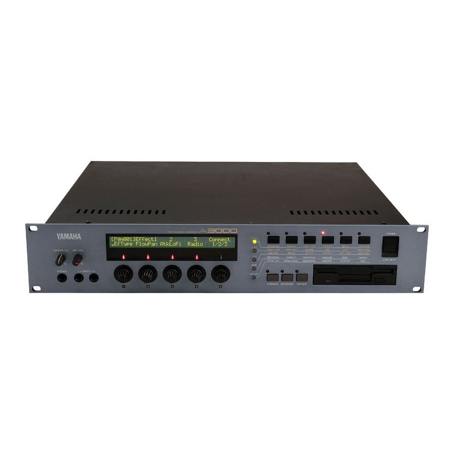
Panel and Connector Arrangement Panel and Connector Arrangement Front Panel (Left Side) MASTER VOL REC VOL PHONES (1) MASTER VOL (Master Volume) Adjusts the output level at the STEREO OUT connectors only. This knob does not affect the output level at the ASSIGNABLE OUT connectors, or at the various connectors provided on the optional I/O expansion board (AIEB1 board). - Page 11 A3000 outputs for realtime output (“A/D In” feature). This knob does not affect the input level to the DIGITAL IN and OPTICAL IN connectors on the optional I/O expansion board (AIEB1 board).
- Page 12 (The A3000 also uses the button lamps to let you know that it is receiving MIDI data. Each lamp corresponds to a different MIDI data type, and will continue to blink while the A3000 is receiving MIDI data of that type.
- Page 13 Press once to switch the power on. Press again to turn the power off. Important The A3000 stores all new data into main memory only, and will lose all of this data when you switch off the power. You must therefore be sure to save all important data to disk before turning the A3000 off.
-
Page 14: Rear Panel
Panel and Connector Arrangement Rear Panel (1) AC inlet Connects to the AC power cord supplied with the A3000. (Please do not use any other power cord with this unit.) (2) MIDI connectors These connectors link the A3000 to external MIDI devices. The MIDI IN connector re- ceives MIDI signals, while the MIDI OUT connector transmits MIDI data generated by the A3000. - Page 15 Additional analog output jacks. Each pair (1&2, 3&4, 5&6) operates independently of all other outputs on the A3000. You can use these jacks to output the sound of one or more selected samples, or to output the signal supplied through the front panel’s analog in- put connectors ( 134, 176).
-
Page 16: A3000 Options
(1) additional memory, and (2) the AIEB1 board (I/O expansion board). Expansion Memory (SIMMs) The A3000 stores all active data in main memory. To play a sample back, you must first load it into main memory. And whenever you record a sample, you must record it into main memory. - Page 17 A3000 Options The I/O Expansion Board (AIEB1 Board) In its standard configuration, the A3000 supports analog I/O only. Although it stores all internal data in digital form, it does not provide direct digital I/O connectors. You can add digital I/O capacity by installing an AIEB1 board. The board offers two different digital connector types: optical connectors, and coaxial connectors.
-
Page 18: Handling The Floppy Disk Drive(Fdd) And Floppy Disk
Be sure to handle floppy disks and treat the disk drive with care. Follow the important precautions below. Disk Type The A3000 disk drive accepts 2HD-type and 2DD-type 3.5" floppy disks. Inserting/Ejecting Floppy Disks To insert a floppy disk into the disk drive: Hold the disk so that the label of the disk is facing upward and the sliding shutter is facing forward, towards the disk slot. - Page 19 • To maintain the disk drive in optimum working order Yamaha recommends that you use a commercially-available dry-type head cleaning disk to clean the head about once a month.
- Page 21 Chapter 1 Setting Up...
-
Page 22: Chapter 1 Setting Up Setting Up
If you have purchased SIMM expansion memory, the AIEB1 expansion board, or an in- ternal hard disk for your A3000, or if you need to connect up an external SCSI disk, please be sure to install this equipment before going through the procedures given in this manual. -
Page 23: Connecting The Power
This page shows you how to connect up the power cord that comes with the A3000. Important • Be sure that the A3000’s power switch is OFF before you attach the cord. (The switch is OFF when it is all the way out.) •... -
Page 24: Connecting The A3000 Outputs
This section explains how to connect the A3000 audio outputs to external devices. Important • Be sure that power to the A3000 and to peripheral devices is OFF before making these • Digital I/O connections are available only if the optional AIEB1 board is installed. - Page 25 ASSIGNABLE OUT STEREO OUT (It is not necessary, of course, to connect up all of the outputs on the expansion board. Connect only the outputs you need to use.) Connecting the A3000 Outputs Amp, mixer, etc. INPUT L/MONO Amp, mixer, etc.
- Page 26 Connecting the A3000 Outputs Connecting the Digital Outputs You can add digital I/O capacity to the A3000 by installing the optional I/O expansion board (AIEB1 board). The board enables direct digital output of A3000 playback and digital through-put. For purposes of compatibility, the AIEB1 board includes two different output types: OPTICAL OUT (optical fiber) and DIGITAL OUT (coaxial cable).
-
Page 27: Connecting The Audio Inputs
This section explains how to connect the A3000 to a microphone, cassette recorder, or other sound source. Important • Be sure that power to the A3000 and to peripheral devices is OFF before making these connections. Connecting devices while power is ON may result in damage to amps or speakers. - Page 28 Coaxial input connection Chapter 1 Setting Up Microphone, etc. Tape recorder, synth, etc. OUTPUT OPTICAL OUTPUT Digital device DIGITAL OUTPUT Digital device A3000 Front Panel INPUT A3000 Front Panel INPUT OPTICAL DIGITAL A3000 Rear Panel OPTICAL DIGITAL A3000 Rear Panel...
-
Page 29: Midi Connections
This section explains how to connect the A3000 to MIDI devices. Important Be sure that power to the A3000 and to peripheral devices is OFF before making MIDI connections. Connecting devices while power is ON may result in MIDI processing er- rors or unexpected and continuous sound output. - Page 30 Pitchbend: Bulk data: MIDI Connection Configurations You can use MIDI connections to control the A3000 from an external keyboard, sequencer, or computer, or to transfer A3000 data to an external MIDI device. Connecting to keyboard or MIDI controller: Connecting to keyboard/controller and external tone generator:...
- Page 31 OUT THRU A wide variety of MIDI connection configurations are available. Design your setup to suit your device and performance requirements. MIDI interface (or tone generator with built-in interface) A3000 Rear Panel MIDI MIDI OUT THRU OUT THRU A3000 Rear Panel...
-
Page 32: Power On/Off
Switch on power to speakers and other audio devices. Power OFF Important • Like other samplers, the A3000 stores all new data into main memory only, and will • Speakers or amplifiers should be switched off first to protect against unexpected sound Chapter 1... - Page 33 Procedure Switch off the amplifiers or speakers. Switch off the power to the A3000. (Press the POWER switch on the front panel.) Switch off external MIDI and SCSI devices. Power ON/OFF Chapter 1 Setting Up...
-
Page 34: Sound Check
Adjust the volume of the speakers or amplifiers. Set the Transmit Channel of your controlling MIDI keyboard to “1”. The A3000’s “Basic Receive Channel” is set to “1” at time of shipping. This means that the A3000 is set to receive data over MIDI Channel 1. - Page 35 Play some keys on your MIDI keyboard. The A3000 should produce a “sine wave” sound when you play the keys. If you hear this sound, the check is successful and you can proceed to Step 9.
- Page 36 Chapter 1 Setting Up...
-
Page 37: Chapter 2 Trying It Out
Chapter 2 Trying It Out... -
Page 38: Introduction
This chapter takes you through a mini-tutorial that will help you become familiar with basic operating methods and give you some initial hands-on experience with your A3000. The practice provided here should help you gain rapid mastery of A3000 operating procedures. - Page 39 Important • Set the “MIDI Transmit Channel” on your MIDI device to “1”. • Descriptions in this chapter assume that you have not changed A3000 settings from their factory default values. Operation may not match the descriptions if settings have been changed.
-
Page 40: Starting Out
Procedure Switch on power to the A3000 and connected devices. Be sure to switch on your devices in the correct sequence. For information about the appropriate power-on sequence, refer to Chapter 1. ( 30) Select REC mode, SETUP function. - Page 41 Turn Knob 2 to select the input. The Input setting selects the input to be recorded. The A3000 records only the signal carried through the connector(s) that you select here. • If you are recording from a monaural microphone connected to the “L” input on the front panel, select AD L.
- Page 42 The StartBy setting selects the trigger that will start the recording. The ManOnly setting means that the A3000 will not begin recording until you push the >START knob. If you set the value to SrcIn, the A3000 will begin recording immediately when the input level reaches some preset trigger level.
- Page 43 Press the third function key. The Meter screen appears. Chant a continuous ahhhh sound into microphone while adjusting the REC VOL knob (on the left side of the front panel) and watching the movement of the meter bar. Adjust so that the bar approaches but stays within the outlined limits.
- Page 44 Striking the key should cause your sample to play back. If you did not hear anything, check the speaker and MIDI connections. You may also need to adjust the MASTER VOL on the A3000 (the far left dial on the front panel), or the output level on your speakers. Memo Notice that you play a program, rather than a specific sample.
- Page 45 Deleting and Redoing If the recording results are not satisfactory, please use the following procedure to delete the recorded sample. Then record the sample again as described in the previous section. Procedure Select PLAY mode, and then select the SAMPLE function (second function button).
- Page 46 Starting Out Press Knob 1 (>DELETE). Press Knob 5 (>YES) to execute the deletion. The new sample is now deleted. You can record it again as described above. Memo In practice, it is not necessary to manually delete the sample as described here in order to replace it with a new one.
-
Page 47: Next Step
In this section we record two more samples, a continuous eeeee sound and a continuous ohhhh sound. We will then assign a name, an original key, and a key range to each of these samples. Finally, we will try out the split keyboard feature. More Recording We begin by recording an eeeee and an ohhhh sample. - Page 48 • If you want to redo only one of the two new samples, delete the bad sample using the Memo Each time you record a sample under an already existing sample name, the A3000 appends a se- quential number to the end of the name. Since you have used the default name for all samples, the...
- Page 49 Changing the Sample Names The A3000 has set non-descriptive default names for your new samples: _NewSample, _NewSample 1, and _NewSample 2. We will now change the names to Voice AH, Voice EE, and Voice OH, respectively. Procedure Select PLAY mode, SAMPLE function.
- Page 50 Next Step Press Knob 3 as many times as necessary to delete all of the characters in the name. Turn Knob 2 to select V. Press Knob 2 (<ENTER>) to enter the new character and move the cursor one space to the right. Repeat steps 7 to 8 in order to enter the rest of the name.
- Page 51 Turn Knob 3 to select <PASTE>. Press Knob 3 (<PASTE>). The name that you just entered (Voice AH) is “pasted” into the name field. Memo Use the paste function to simplify the work of entering names. This feature lets you reinput a previ- ous character string with a single press on the knob.
- Page 52 Next Step Setting the Original Key and the Key Range Notice that striking a key on your MIDI keyboard will replay all three of your samples at the same time. For our first “sample edit” session, we will now set the samples so that keyboard keys from C2 to B2 produce Voice AH, while keys C3 to B3 produce Voice EE, and keys C4 to B4 produce Voice OH.
- Page 53 Turn Knob 2 to set the OrigKey (original key) value to C2. Then turn Knob 3 to set Low to C2, and turn Knob 4 to set High to B2. As you can see, the “original key” is now set to C2, while the key range is C2 to B2. Press Knob 1, and then turn Knob 2 or Knob 3 to select Voice EE for editing.
-
Page 54: Sample Editing
Sample Editing In this section we will try out further editing on your ahhhh, eeeee, and ohhhh samples. Using Loops We will now set up a loop for the ahhhh sample. The sample will then play out continu- ously when you hold down an appropriate key at the MIDI keyboard. Procedure Select EDIT mode, and then select the TRIM/LOOP function. - Page 55 Memo Notice that you can use the AUDITION key in place of the MIDI keyboard to play out the sound of your samples. Turn Knob 1 to select the Config (Configure) screen. Then turn Knob 3 to set Zero to on. The zero feature (also known as automatic zeroing) eliminates the cracking sound that may occur when playback jumps from the loop endpoint to the loop start point.
- Page 56 Now play a key between C3 and B3 at your keyboard. Memo The A3000 offers a variety of filter types. You can select from among two high-pass filters (HiPass1, HiPass2), two low-pass filters (LowPass1, LowPass2), a band-pass filter (BandPass), and a band- eliminate filter (BandElim).
- Page 57 • The A3000 also provides a filter EG (“FEG”) and pitch EG (“PEG”). You use these features to select how filtering and pitch develop over time while the key is held down.
- Page 58 Sample Editing Using the LFO We will now set the LFO (low-frequency oscillator) to create a vibrato in the ahhhh sample. Procedure Select EDIT mode, LFO function. Press Knob 1, and then turn Knob 2 or Knob 3 to select the Voice AH sample for editing.
-
Page 59: Program Editing
The screen should now look like this. Memo The A3000 allows you to assign up to three effects (Effect1, Effect2, and Effect3) to each program. You can then apply any one of these effects to each of the samples used by the program. The MainOut setting determines which of the effects is applied to the sample. - Page 60 ProgramEditing Select PLAY mode, EFFECT function. Turn Knob 1 to select the EfType (effect type) screen. Then turn Knob 2 to set Effect1 to FlngPan (flanging pan). Now play a key between C3 and B3 at your keyboard. Notice how the flange effect pans back and forth from right to left. Editing a Different Program Now we will see how to set up and edit another program.
- Page 61 Turn Knob 2 or Knob 3 to set Program to 002:“Pgm 002”. The screen should now look like this. Try playing at the keyboard to see what happens. Nothing happens. Program 002 is still empty, since we have not yet assigned any sam- ples to it.
- Page 62 ProgramEditing Memo • Notice that there was no need to go through this procedure for Program 001, which was ready to • Notice also that the keyboard ranges for all three samples are the same for both programs. This is Next, let’s try dropping the pitch of Voice AH by one octave, and then raising the pitch of Voice OH by the same amount.
- Page 63 Turn Knob 4 or Knob 5 to set the value to -12. Press Knob 1, then turn Knob 2 or Knob 3 to select Voice OH for easy editing. Then press Knob 1 again. Turn Knob 4 or Knob 5 to set the coarse tune value to +12. Try playing at the keyboard.
-
Page 64: Sequence Play
In this section you will learn how to record and play a sequence. Recording the Sequence Here we will record a sequence that makes use of Program 001. Note that a sequence is a stream of MIDI performance data that you record from your keyboard into the A3000 for later playback. Procedure Select PLAY mode, PROGRAM function. - Page 65 Knob 5 (>STOP). Playing the Sequence Now let’s play back the sequence that you just recorded. Procedure Press Knob 5 (>PLAY). The A3000 starts replay of the recorded sequence. Press Knob 5 (>STOP). The replay stops. Sequence Play Chapter 2...
-
Page 66: Saving And Reloading Your Data
Saving and Reloading Your Data Like other samplers, the A3000 stores all new data into main memory only, and will lose all of this data when you switch off the power. You must therefore be sure to save all important data to disk before turning the A3000 off. -
Page 67: Saving Your Data
Press Knob 1 (>FD_FMT). The following confirmation prompt appears. Press Knob 5 (>YES). The A3000 starts to format the disk. Please wait until the original screen returns, indicating that the format is finished. Saving Your Data The next procedure shows how to save all of your new data to floppy disk. - Page 68 PANEL PLAY SEQUENCE UTILITY The screen should now look like this. The following confirmation prompt appears. The A3000 starts to save the data. Please wait until the original screen returns, indi- cating that the save is finished. EFFECT SETUP CONTROL...
-
Page 69: Loading Data From Disk
Loading Data from Disk The section shows you to reload the saved disk data back into the A3000. Procedure Select DISK mode, DISK function. If necessary, turn Knob 1 to select the Disk page. PLAY EDIT DISK UTILITY The screen now looks like this. -
Page 70: Accompanying Disks
Track 1 of the CD-ROM contains A3000-format data (non-audio data) that can be loaded directly into the A3000. To load this data, you will need to insert the disk into a SCSI CD-ROM drive connected to the A3000’s SCSI connector. -
Page 71: Chapter 3 Basics
Chapter 3 Basics... -
Page 72: Samples And Programs
Despite their differences, samples and programs both meet this definition, and may both be referred to as objects. When playing sounds from the A3000, you play the programs rather than the individual samples. As an example, assume that you have created three samples in A3000 memory: a “piano”... - Page 73 Select Digital data representing an acoustic sound wave. You generally create this data by recording sound at the A3000, using input from a microphone or some external audio device. Note that the process of recording acoustic sound in digital form is known as sampling.
- Page 74 • An A3000 sample may be either stereo or monaural. A stereo sample contains two • The amount of available memory determines the length and number of samples that • The A3000 offers a special object type, referred to as a sample bank. The sample bank Programs A program is a playable collection of samples and other data.
- Page 75 Memory Sample A Wave data Sample parameters Program 001 ToPgm switch Program Parameters Easy-edit parameters Program 002 ToPgm switch Program Parameters Easy-edit parameters Program 128 ToPgm switch Program Parameters Easy-edit parameters Program Setup Example 1 We can now set up some programs by plugging in values for the various data types indicated above.
- Page 76 Samples and Programs Selection of Program 1 causes the A3000 to play a piano sound (Sample A) each time any key on the keyboard is hit. (Note that the key range is set from C-2 to G8, covering the entire keyboard.) A reverb effect is applied to the sound.
- Page 77 The above adjustment removes the overlap. Program 2 will now play the bass sample over keyboard range C2 to B3, and the sax sample over range C4 to B5. Program Setup Example 2 In this example, we assign a different MIDI Receive Channel to each sample. Sample A: Piano.
- Page 78 Once you have produced these samples, you will want to keep them together and treat them as a group. The A3000 therefore lets you handle the entire group of samples as a single unit, called a sample bank.
- Page 79 • Multiple samples can be grouped into a single sample bank. You can then treat the sample bank as a single “virtual” sample. • When playing sound from the A3000, you do not select and play at the sample level. Instead, you create programs that utilize the samples, and then play the programs.
-
Page 80: Sample Output Destinations And Effects
Sample Output Destinations and Effects Each sample includes output parameters that select the sample’s output destination and effects usage. The A3000 provides a double-output system (main output and assignable output) and a triple effect system (three independent effect circuits). Double Output System You can output each sample to two different output systems: a main output and an assignable output. - Page 81 Triple Effect System The A3000 allows each program to use up to three effects. The three effects are imple- mented as independent, parallel circuits. It is also possible, however, to “rewire” any or all of these circuits into a serial configuration ( 121).
-
Page 82: Data Configuration And Handling
Data Configuration and Handling The A3000 main memory loses all data at power off. It is therefore essential that you save all important data to disk before you switch off the power. Of course, you must also reload the data you wish to use each time you switch the power back on. - Page 83 Disks and Volumes The A3000 includes a built-in floppy disk drive. You may also connect the A3000 to an external SCSI drive, or install an internal SCSI drive (provided that you also install the optional ASIB1 expansion board). Disks You can store data to floppy disk, or (if an ASIB1 is installed) to hard disk, MO disk, or any other type of SCSI disk medium.
-
Page 84: Chapter 3 Basics
The point to remember here is that each disk volume corresponds exactly to a full set of main-memory data. As the next illustration shows, the A3000 saves all main-memory data into a single volume. When you reload the volume, you restore the main memory to its exact state at the time of the data save. - Page 85 The use of a “volume save” makes it easy to save the entire main-memory content before switching the A3000 off, so that you can then restore the identical environment the next time you switch the power back on. You can resume work exactly where you left off, with all of your samples and programs intact.
-
Page 86: Modes And Functions
Modes and Functions Modes and Functions The A3000 provides five operating modes: PLAY, EDIT, RECORDING, DISK, and UTILITY. Each mode is subdivided into six functions. Modes PLAY mode Use this mode to select, play, and edit your programs. The mode lets you access and edit all program parameters, set up programs for playback, and carry out playback. -
Page 87: Edit Functions
UTILITY mode: Set system-wide parameters; record and replay sequences. Memory System Parameters Sequence Data Program 001 PLAY mode: Edit any Program Parameters program. Program 002 Program Parameters Program 128 Program Parameters Functions Each mode offers six different functions. The functions for each mode are as follows. PLAY functions PROGRAM, SAMPLE, EASY EDIT, EFFECT, SETUP, CONTROL EDIT functions... -
Page 88: Basic Operation
The following Filter screen will then appear. Selecting the Screen When you select a function as described above, the A3000 displays a corresponding screen that you can use to change various settings or execute an operation. Most func- tions, however, contain too many selections for a single screen — and therefore offer you multiple screens, each with a different group of settings or operations. -
Page 89: Changing The Settings
Changing the Page with Knob 1 As mentioned above, you can switch from one page to another (within the same func- tion) by turning Knob 1. Turn the knob one click to the right to advance to the next page, or one click to the left to move back one page. Assume that you have just selected the EDIT mode’s FILTER function and are looking at the first page (Filter page). -
Page 90: Executing An Operation
Entering a Character You use Knob 2 to enter a character at the cursor position. Rotate the knob until the desired alphanumeric appears. Note that the A3000 supports both uppercase and lowercase letters. Chapter 3 Basics... - Page 91 Replacing with Most Recent Name (“Pasting”) This A3000 stores the most recently entered name into a special “paste” buffer. When you are ready to enter another name, you can insert the buffer content by turning Knob 3 to select <PASTE>, and then pressing Knob 3 to execute.
- Page 92 The blinking indication means that the A3000 is ready to set the value in accordance with the input received at the MIDI IN connector. You can now make the setting by striking the appropriate key at the key- board.
-
Page 93: Other Keys And Operations
This type of direct sample playback is available only with the AUDITION key. If you press this key when working with a sample bank, the A3000 plays out each sample in the bank, one after the other. -
Page 94: Midi Indicator
You can set this feature up using the PLAY mode SETUP function. ( 132) MIDI Indicator The A3000 lets you know that it is currently receiving MIDI data by blinking one of the lamps on its five mode buttons. The blinking lamp indicates the type of data that com- ing in, as follows. - Page 95 Chapter 4 PLAY Mode...
-
Page 96: Chapter 4 Play Mode Play Mode
Play Mode You use PLAY mode to edit, arrange, and play A3000 programs. PLAY-Mode Functions PLAY mode consists of the six functions described below. PROGRAM You use the PROGRAM function to select programs for replay or editing, to save edited programs to disk, and to carry out normal playback. -
Page 97: Program & Sample Selection Screen
Program & Sample Selection Screen The A3000 includes a special selection screen that you can access at almost any time by pushing Knob 1. You can then use the screen to select a sample or program for playback or editing, and to set a number of other features as described below. - Page 98 Program & Sample Selection Screen Knob 1 Program • Turn the knob to select a program. • Push the knob to return to the previous screen. Knobs 2, 3 Sample Turn the knob to select a sample. The name of the selected sample appears on the sec- ond line of the screen.
- Page 99 — but it is not possible for you to designate which of these is selected. • If you strike a key that plays a sample that exists within a sample bank, the A3000 selects the entire sample bank, rather than the individual sample. An exception, how- ever, is noted directly below.
-
Page 100: Command Pages
• Turn the knob to change to a different command page. • Push the knob when you are ready to execute the save. The A3000 returns a confir- • If a name conflict occurs (if the selected object in main memory has the same name... - Page 101 AllPgm(wp) Edited AllSmp Destination Type = Dsk, Vol, Pgm Knob 3 Use this knob together with Knob 4 or 5 to select the destination for the save. As an example, suppose that you want to save the currently selected program into Pro- gram Number 005 on Volume “B”...
- Page 102 • If you select One, the A3000 will display the above-shown command page each time • If you select All, the A3000 will apply your instructions to all same-name samples that Note that the One/All selection has no meaning if you are saving a single sample only, or if you are saving a sequence.
-
Page 103: Init (Program Initialization)
• Turn the knob to change to a different command page. • Push the knob to execute program initialization. The A3000 then returns a confirma- tion screen. Push Knob 5 (>YES) to complete the initialization, or Knob 4 (>NO) to cancel. -
Page 104: Copy
Turn action Push action Use this page to copy (replicate) a program. The A3000 copies all data from the selected memory-resident program into the destination memory-resident program. Following the copy, the two programs will have identical data but different program numbers. -
Page 105: Pgmdump (Program Dump)
• If you select off, the A3000 transmits program data only. • If you select on, the A3000 transmits the program data together with all data from all samples used by the program. (Sample data is transmitted in A3000 proprietary for- mat.) -
Page 106: Setinit (Set Program's Initial Conditions)
FECT] (Knob 2) to on, and then push Knob 1 to execute. Important • The settings that you make here are stored in nonvolatile memory, and are not lost at • The A3000 accepts initial settings only for the program’s EFFECT, SETUP, and CON- Knob 1 Change Page •... -
Page 107: Newbank (Create A Sample Bank)
Change Page • Turn the knob to change to a different command page. • Push the knob to execute. The A3000 returns a confirmation screen. Push Knob 5 (>YES) to create the bank, or Knob 4 (>NO) to cancel. Knobs 4, 5 If you wish to change the name, push either knob to proceed to the name editing screen. -
Page 108: Delete
• Turn the knob to change to a different command page. • Push the knob to delete the sample(s). The A3000 returns a confirmation screen. • If you select a sample bank for deletion, the A3000 screen will ask whether you want Type of Deletion = Smp, AllSmp, FreeSmp... -
Page 109: Dupl (Duplicate)
• If you duplicate a sample bank, the A3000 duplicates both the bank and all of the samples within the bank. (The name for each new sample becomes: original name + “*”.) -
Page 110: Smpdump (Sample Dump)
Knob 1 Change Page • Turn the knob to change to a different command page. • Push the knob to execute the sample dump. The A3000 returns a confirmation screen. Sample Knobs 2, 3 • Turn either knob to select the sample or sample bank that you want to dump. - Page 111 Set the value to on if you want to include the sample data, or off if you want to send the bank data only. (If you set the value to on, the A3000 dumps the component samples in A3000 proprietary format.) COMMAND Pages...
-
Page 112: Program Function
PROGRAM Function PROGRAM Function This section describes the PLAY-mode PROGRAM function. You use this function to select programs for replay or editing, to save edited programs to disk, and to carry out normal playback. PROGRAM - PgmSel (Select Program) Selects program for playback or editing, or saves data to disk PLAY PROGRAM SAMPLE... - Page 113 ( 266), and always to the same program number. (For example, if you are saving Pro- gram 005 from main memory, the A3000 will save the data into Program 005 on disk.) If you wish to save to a different volume or program number, do not use this screen. Use the SAVE command page instead (press the COMMAND key and go to the >SAVE com-...
-
Page 114: Sample Function
SAMPLE Function This section describes the PLAY-mode SAMPLE function. You can use this function to assign samples to programs, to save samples to disk, and to build sample banks. SAMPLE - SmpSel (Select Sample) Selects sample (or sample bank) for playback or editing, or saves data to disk. PLAY PROGRAM SAMPLE... - Page 115 (or 2 stereo samples). Knob 5 • Push this knob to save the selected sample or sample bank. The A3000 then returns a confirmation screen. Push Knob 5 (>YES) to execute the save, or Knob 4 (>NO) to cancel.
-
Page 116: Sample - Smpbnk (Select Sample From Sample Bank)
SAMPLE Function SAMPLE - SmpBnk (Select Sample from Sample Bank) Selects a sample from a sample bank. PLAY PROGRAM SAMPLE EASY EDIT EDIT TRIM / LOOP MAP / OUT RECORD SETUP DISK PROGRAM SAMPLE SEQUENCE UTILITY TOTAL EQ PANEL PLAY SEQUENCE Turn action Push action... -
Page 117: Sample - Tobank (Assign Sample To Bank)
SAMPLE - ToBank (Assign Sample to Bank) Places a sample into a sample bank. PLAY PROGRAM SAMPLE EASY EDIT EFFECT EDIT TRIM / LOOP MAP / OUT FILTER RECORD SETUP METER EFFECT DISK PROGRAM SAMPLE SEQUENCE VOLUME UTILITY TOTAL EQ PANEL PLAY SEQUENCE MASTER... - Page 118 Chapter 4 PLAY Mode to a program. If you select a sample that is already assigned, therefore, the A3000 will display a Duplicate & Add? prompt screen — giving you a chance to generate a new copy of the sample for inclusion into the selected bank.
-
Page 119: Sample - Smpsort (Sort Samples)
SAMPLE - SmpSort (Sort Samples) Sorts the order in which sample names appear on the screen. PLAY PROGRAM SAMPLE EASY EDIT EFFECT EDIT TRIM / LOOP MAP / OUT FILTER RECORD SETUP METER EFFECT DISK PROGRAM SAMPLE SEQUENCE VOLUME UTILITY TOTAL EQ PANEL PLAY SEQUENCE... -
Page 120: Easy Edit Function
EASY EDIT Function EASY EDIT Function This section describes the PLAY-mode EASY EDIT function. You use easy-editing to adjust the sound of the samples used by the selected program. Important • These adjustments are applied by the program, and do not alter the settings stored •... -
Page 121: Easy Edit - Easyed
EASY EDIT - EasyEd Adjust the sound of samples used within the program. PLAY PROGRAM SAMPLE EASY EDIT EFFECT EDIT TRIM / LOOP MAP / OUT FILTER RECORD SETUP METER EFFECT DISK PROGRAM SAMPLE SEQUENCE VOLUME UTILITY TOTAL EQ PANEL PLAY SEQUENCE MASTER Knob 1... - Page 122 EASY EDIT Function Poly/Mono Poramento AlternateGrp Main Output Main Out level Assign Output Assign Out Lvl MIDI ReceiveCH MIDI Control * You can use these settings only to reduce the sample’s internally-set key range. Set- † You can use these settings only to reduce the sample’s internally-set velocity range. ‡...
-
Page 123: Effect Function
• The sample’s “main output” destination determines the effect that the sample re- ceives. In particular, the A3000 does not apply any effect to samples whose main output is set to off or to Stereo. To apply an effect to a sample, make sure that the sample’s main output is set to Effect1, Effect2, or Effect3. - Page 124 Samples whose main output destination is to Effect1 move through the Effect-1 block only (receive Effect 1 only) and then pass the A3000’s stereo outputs. Similarly, samples with main output destination set to Effect2 or Effect3 move through the corresponding block only and then pass to the stereo outputs.
- Page 125 1/2/3 Samples set to Main Output=Effect1 Samples set to Main Output=Effect2 Samples set to Main Output=Effect3 1 2/3 Samples set to Main Output=Effect1 Samples set to Main Output=Effect2 Samples set to Main Output=Effect3 1 2 3 Samples set to Main Output=Effect1 Samples set to Main Output=Effect2 Samples set to Main Output=Effect3 EFFECT Function...
-
Page 126: Effect - Efct1
EFFECT Function EFFECT - Efct1,...,Efct3 (Edit the Effects) Use this page to edit the effects selected for the current program. The page’s appearance and operation varies according to whether “EffectEditType” value is set to “full” or “favorite” ( 127). If “EffectEditType” is set to “full”, the page appears as follows. Sets parameters for the selected effect (Effect 1, 2, or 3). - Page 127 If “EffectEditType” is set to “favorite”, the page looks like this. Sets parameters for the selected effect (Effect 1, 2, or 3). PLAY PROGRAM SAMPLE EASY EDIT EFFECT EDIT TRIM / LOOP MAP / OUT FILTER RECORD SETUP METER EFFECT DISK PROGRAM SAMPLE...
-
Page 128: Effect - In&Out (Input/Output Levels And Pan)
EFFECT Function EFFECT - In&Out (Input/output levels and pan) Sets input level, output level, and pan for each effect (Effects 1, 2, and 3). PLAY PROGRAM SAMPLE EASY EDIT EDIT TRIM / LOOP MAP / OUT RECORD SETUP DISK PROGRAM SAMPLE SEQUENCE UTILITY... -
Page 129: Effect - Edtype (Effect Edit Type)
EFFECT - EdType (Effect Edit Type) Selects the effect-edit method: either “full” or “favorite.” PLAY PROGRAM SAMPLE EASY EDIT EFFECT EDIT TRIM / LOOP MAP / OUT FILTER RECORD SETUP METER EFFECT DISK PROGRAM SAMPLE SEQUENCE VOLUME UTILITY TOTAL EQ PANEL PLAY SEQUENCE MASTER... -
Page 130: Setup Function
SETUP Function The PLAY-mode SETUP function lets you set each program’s general output level, trans- position, portamento, and A/D-input. SETUP - PgmMstr (Program’s Master Settings) Sets the program’s output level, transposition, and LFO “sample & hold” speed. PLAY PROGRAM SAMPLE EASY EDIT EDIT TRIM / LOOP... - Page 131 S/H. Specifically, the setting determines the “sample and hold” rate used for random LFO modulation. (Note that the term “sample” in “sample & hold” refers to sampling rate, and is unrelated to A3000 sound samples.) This setting has meaning only if the program uses at least one sample for which Wave=S/H.
-
Page 132: Setup - Portmnt (Portamento)
• The “rate” settings select a fixed-rate slide, while the “time” settings select a fixed- • If you select a “fingered” portamento, the A3000 applies a slide between two consecu- • Note that the “fingered” setting is effective only on samples that are set for one-note-... - Page 133 time(fingered) time(fulltime) Rate/Time Knob 4 This value sets the pitch slide rate or slide time. The setting determines the slide rate (if the mode is set to “rate”) or the slide time (if the mode is set to “time”). SETUP Function Slides one note into the next only if the first note (key) is still held when the next note is struck.
-
Page 134: Setup - Adsetup (A/D-In Setup)
The A/D-input feature lets you feed an acoustic signal from an external device (typically a microphone) through the A3000. You can set the signal to receive any one of the program’s three effects, or you can relay the signal through the A3000 without change. - Page 135 SETUP Function = -63,...,+63 Knob 4 This value sets the pan (stereo positioning) for the output from the A/D-input signal. Positive values set pan to the right; negative values set pan to the left. If Source is set to L/R, higher absolute pan settings will narrow the stereo feeling while noticeably shifting the sound position.
-
Page 136: Setup - Adout (Output Setup For A/D-Input Signal)
SETUP Function SETUP - ADOut (Output Setup for A/D-Input Signal) Selects the output destinations for the A/D-in signal, and sets the output levels. PLAY PROGRAM SAMPLE EASY EDIT EDIT TRIM / LOOP MAP / OUT RECORD SETUP DISK PROGRAM SAMPLE SEQUENCE UTILITY TOTAL EQ... - Page 137 • Set this value to off if you do not want to output the signal to any assignable output. Set the value to ASL&R if you want to output the signal to the A3000’s standard assignable-output pair. The other settings are meaningful only if you have installed the optional I/O expansion board (AIEB1 board);...
-
Page 138: Control Function
SYSTEM MIDI Knob 1 Knob 2 Knob 3 Selects a controller. Selects the controlled Matrix No. parameter. Matrix# Device Function Knob 4 Knob 5 Determines how the A3000 converts the received controller values. Sets the maximum control range. Type Range... - Page 139 Use this setting to select the external physical controller that you want to set for opera- tion with the A3000. The setting selects one of the controllers on your external MIDI device. You can then use Knob 4 (and also the PgmCtl2 page) to determine how this controller affects the playback of this program.
- Page 140 CONTROL Function Function Knobs 4, 5 Use this setting to select the parameter to be controlled by the controller selected by Knob 2. Choices are listed below. For more information, refer to the indicated pages. Function Portament R/T S/H Speed AD Pan AD Level Program level...
-
Page 141: Control - Pgmctl2 (Program Controller Setup 2)
The transmitted values always range from 0 to 127. Upon receiving the value, the A3000 converts it as specified here, and then applies it to the parameter selected by the Function entry ( 138). The conversion determines how strongly (and in which direction) the parameter changes in response to the controller’s... - Page 142 • A negative setting reverses the controller’s normal direction. For example, moving a Chapter 4 PLAY Mode The A3000 converts the received value (0 to 127) to a corre- sponding value in the range {0 to range}, and adds the result to the target parameter. Notice that the resulting offset is therefore always positive (or always negative, depending on the Range sign;...
-
Page 143: Control - Reset (Controller Reset)
CONTROL - Reset (Controller Reset) Selects whether controllers initialize when you switch into this program. PLAY PROGRAM SAMPLE EASY EDIT EFFECT EDIT TRIM / LOOP MAP / OUT FILTER RECORD SETUP METER EFFECT DISK PROGRAM SAMPLE SEQUENCE VOLUME UTILITY TOTAL EQ PANEL PLAY SEQUENCE MASTER... - Page 144 Sample A. Finally, assume that you now switch to Program 002, using either the A3000 panel or a program-change message from your MIDI keyboard. The behavior of Sample B when you first switch into Program 002 depends on whether or not the controller value is reset.
- Page 145 Chapter 5 EDIT Mode...
-
Page 146: Chapter 5 Edit Mode Edit Mode
EDIT Mode You use EDIT mode to edit your samples and sample banks. EDIT-Mode Functions EDIT mode comprises the six functions described below. TRIM/LOOP Use this function to select the playback area on the waveform (the playback “start” and “end” points), to trim off extraneous waveform data, and to set up the playback direction (forward or backward) and loop characteristics (loop range and type). - Page 147 If you like, you can select a specific value for the parameter by rotating the corresponding knob. If you do this, the A3000 will apply the value you select to all of the samples in the bank, temporarily overriding their local settings. If you wish to cancel the bank-level setting and return the samples to their original values, turn the knob to reselect the “----”.
- Page 148 EDIT mode. To switch to a different sample, push Knob 1 on the edit screen you are working at. If switching is supported, the A3000 will now display the Program/Sample selection screen. Turn Knob 2 or 3 to select the next sample you want to edit. Then press Knob 1 again to return to the previous edit screen, with the new sample now selected.
-
Page 149: Command Pages
• Turn the knob to change to a different command page. • Push the knob when you are ready to execute the save. The A3000 returns a confir- mation prompt. Push Knob 5 (>YES) to proceed with the save, or Knob 4 (>NO) to cancel. - Page 150 Saves all samples into the destination volume. Saves the currently selected sample (or sample bank) to the des- tination volume. If a sample bank is selected, the A3000 also saves all of the samples used in the bank. Use this to view or change the destination-disk setting. When you select Dsk, the identity of the currently selected disk appears above Knobs 4 and 5.
-
Page 151: Revert
Change Page • Turn the knob to change to a different command page. • Push the knob to execute the reversion. The A3000 returns a confirmation screen. Push Knob 5 (>YES) to proceed, or Knob 4 (>NO) to cancel. SETUP... -
Page 152: Norm (Normalize)
This command does not operate on sample banks. Knob 1 Change Page • Turn the knob to change to a different command page. • Push the knob to execute the normalization. The A3000 returns a confirmation screen. Chapter 5 EDIT Mode EFFECT... -
Page 153: Resmpl - Tmstrch (Resampling - Time Stretch)
Change Page • Turn the knob to change to a different command page. • Push the knob to execute the time conversion. The A3000 returns a confirmation screen. Push Knob 5 (>YES) to proceed, or Knob 4 (>NO) to cancel. - Page 154 COMMAND Pages Length Knobs 3, 4 Turn either knob to set the time adjustment. Values above 100% lengthen the sample, while values below 100% compress it. Accuracy Knob 5 Time-stretch conversion does not produce perfect results, and involves a tradeoff be- tween sound and rhythm quality.
-
Page 155: Resmpl - Ptchcnv (Resampling - Pitch Conversion)
Change Page • Turn the knob to change to a different command page. • Push the knob to execute the pitch conversion. The A3000 returns a confirmation screen. Push Knob 5 (>YES) to proceed, or Knob 4 (>NO) to cancel. - Page 156 COMMAND Pages Fine Knob 4 Use this knob to raise or lower the pitch in increments of 1.171875 cents. (Note: 100 cents = 1 semitone.) Accuracy Knob 5 Time-fixed pitch adjustment does not produce perfect results, and involves a tradeoff between sound and rhythm quality.
-
Page 157: Fade
Knob 1 Change Page • Turn the knob to change to a different command page. • Push the knob to execute processing. The A3000 returns a confirmation screen. Push Knob 5 (>YES) to proceed, or Knob 4 (>NO) to cancel. In/Out Knob 2 Turn the knob to select whether the sample uses fade-in or fade-out. - Page 158 COMMAND Pages Curve Knob 3 This setting selects the curve type for the fade. Three types are available, as illustrated below. Length Knob 4 Turn the knob to set the length for the fade, in “address” units. The minimum length is 0 (no fade).
-
Page 159: Revers (Reverse)
Change Page • Turn the knob to change to a different command page. • Push the knob to execute the reversal. The A3000 returns a confirmation screen. Push Knob 5 (>YES) to proceed, or Knob 4 (>NO) to cancel. SETUP... -
Page 160: Loopxfd (Loop Crossfade)
Knob 1 Change Page • Turn the knob to change to a different command page. • Push the knob to register the crossfade. The A3000 returns a confirmation screen. Width Knob 2: Sets the length of the crossfade area, as a percentage of the total loop length. - Page 161 Processing if Area = sustain: Start Address Loop Start Address Step 1: Copy waveform piece from end of segment A-B into a buffer. Extract piece of equal length from the end of C-D, and copy into another buffer. The length of these pieces is determined by the Width setting. Step 2: Apply fade-in processing to the A-B piece, and fade-out processing to the C-D piece.
-
Page 162: Setinit (Register Initial Parameter Values)
The initial settings are stored in nonvolatile memory, and are not lost at power-off. Knob 1 Change Page • Turn the knob to change to a different command page. • Push the knob to register the new initial values. The A3000 returns a confirmation Chapter 5 EDIT Mode EFFECT... -
Page 163: Trim/Loop Function
TRIM/LOOP Function This section describes the EDIT mode’s TRIM/LOOP function. You use this function to change the playback area on the waveform (the playback “start” and “end” points), to trim off extraneous waveform data, to set the playback direction (forward or backward) and loop characteristics (loop range and type), and to make various other related set- tings. - Page 164 TRIM/LOOP Function Length Knob 2 This option lets you lock in the waveform’s play length (the distance between the wave start and wave end addresses) and loop length (the distance between the loop-start and loop-end addresses). You enable this option by setting it to lock. If you do this, any change you make to any of these addresses will generate an equal change in the corresponding address —...
- Page 165 Snap Knob 4 The “automatic snap” option is useful when you are editing loop start and loop end addresses. If you enable this option, then you will only be able to change a loop address to those points on the waveform that have the same level as the opposing loop address; the address you are editing will jump from one such point to the next as you turn the knob.
-
Page 166: Trim/Loop - Wave (Edit Waveform)
TRIM/LOOP Function TRIM/LOOP - Wave (Edit Waveform) Sets start and end addresses, and “trims” the waveform. PLAY PROGRAM SAMPLE EASY EDIT EDIT TRIM / LOOP MAP / OUT RECORD SETUP DISK PROGRAM SAMPLE SEQUENCE UTILITY TOTAL EQ PANEL PLAY SEQUENCE Turn action Push action Use this page to select the playback start and end points on the waveform. - Page 167 Start Address When you push the knob, the A3000 returns a confirmation screen. Push Knob 5 (>YES) to proceed, or Knob 4 (>NO) to cancel. Note that the deleted waveform area cannot be recovered (unless you have already saved the data to disk.)
-
Page 168: Trim/Loop - Loop (Edit Loop Addresses)
TRIM/LOOP Function TRIM/LOOP - Loop (Edit Loop Addresses) Sets loop start and loop end addresses. PLAY PROGRAM SAMPLE EASY EDIT EDIT TRIM / LOOP MAP / OUT RECORD SETUP DISK PROGRAM SAMPLE SEQUENCE UTILITY TOTAL EQ PANEL PLAY SEQUENCE Turn action Push action Use this page to select the start and end points for the playback loop. - Page 169 If you set the value to -500ms and then press the knob, for example, the A3000 begins replay from a point 1/2 second before the loop start. (This lead-in is played only once, and does not recur after the loop is entered.)
-
Page 170: Trim/Loop - Wvmode (Set Wave Mode)
TRIM/LOOP Function TRIM/LOOP - WvMode (Set Wave Mode) Sets the loop mode and the start-address velocity sensitivity. PLAY PROGRAM SAMPLE EASY EDIT EDIT TRIM / LOOP MAP / OUT RECORD SETUP DISK PROGRAM SAMPLE SEQUENCE UTILITY TOTAL EQ PANEL PLAY SEQUENCE Turn action Push action... - Page 171 Address Settings Loop Loop Start Address Address Start Address Loop Mode = “ ” (Forward, No Loop): Loop Mode = “ ” (Forward Loop, No Exit): Loop Mode = “ ” (Forward Loop, Exit at Note-Off) Loop Mode = “ ”...
-
Page 172: Map/Out Function
= C-2,...,G8 sample’s inherent pitch. indicator begins blinking, indicating that the A3000 is ready to receive MIDI input. Transmit the appropriate note value, then lock the setting in by pressing the knob again (or else press a different MIDI IN knob, or change to a different screen). - Page 173 Knob 3 • Turn the knob to set the low end for the sample’s key range. • Push the knob if you want to set the value using MIDI input. Be sure that the knob indicator is blinking, then transmit the note from your MIDI device. Then press the same knob again, or else press a different MIDI IN knob or change to a different screen.
-
Page 174: Map/Out - Velrnge (Velocity Range)
= 0,..., High velocity sample. (But refer also to the explanation for Knob 4, below.) indicator begins blinking, indicating that the A3000 is ready to receive MIDI input. Now transmit any note, taking care to use the appropriate velocity (key-strike force). - Page 175 Positive values causes output level to increase with increasing velocity, while nega- tive settings have the opposite effect. • You can use the UTILITY | MIDI Adjust page to set the adjustment that the A3000 applies to received velocity values before transmitting them to the internal tone gen- erator.
-
Page 176: Map/Out - Lvl&Mode
MAP/OUT Function MAP/OUT - Lvl&Mode Sets the sample’s level, pan, portamento, and poly/mono switch. PLAY PROGRAM SAMPLE EASY EDIT EDIT TRIM / LOOP MAP / OUT RECORD SETUP DISK PROGRAM SAMPLE SEQUENCE UTILITY TOTAL EQ PANEL PLAY SEQUENCE Turn action Push action Use this page to set the sample’s level, pan, portamento, and poly/mono switch. - Page 177 If sample is monaural: Pan = -63 If sample is stereo: Pan = -63 Pan = -32 Poly/Mono Knob 4 Select Mono if you want to limit playback of this sample to one note at a time. Select Poly to enable simultaneous playback of multiple notes. Porta Knob 5 •...
-
Page 178: Map/Out - Output
MAP/OUT Function MAP/OUT - Output Sets the sample’s output destinations and output levels. PLAY PROGRAM SAMPLE EASY EDIT EDIT TRIM / LOOP MAP / OUT RECORD SETUP DISK PROGRAM SAMPLE SEQUENCE UTILITY TOTAL EQ PANEL PLAY SEQUENCE Turn action Push action Use this page to set the sample’s main and assignable output destinations, and the out- put level to each. - Page 179 • Set this value to off if you do not want to output the signal to any assignable output. Set the value to ASL&R if you want to output the signal to the A3000’s standard assignable-output pair. The other settings are meaningful only if you have installed the optional I/O expansion board (AIEB1 board);...
-
Page 180: Map/Out - Pitch
MAP/OUT Function MAP/OUT - Pitch Sets the sample’s pitch characteristics. PLAY PROGRAM SAMPLE EASY EDIT EDIT TRIM / LOOP MAP / OUT RECORD SETUP DISK PROGRAM SAMPLE SEQUENCE UTILITY TOTAL EQ PANEL PLAY SEQUENCE Turn action Push action Use this page to set the sample’s tuning and pitch characteristics. Knob 1 Change Page •... -
Page 181: Map/Out - Expand
MAP/OUT - Expand Sets the sound’s expansion characteristics. PLAY PROGRAM SAMPLE EASY EDIT EFFECT EDIT TRIM / LOOP MAP / OUT FILTER RECORD SETUP METER EFFECT DISK PROGRAM SAMPLE SEQUENCE VOLUME UTILITY TOTAL EQ PANEL PLAY SEQUENCE MASTER Knob 1 Turn action Push action Use this page to create a more expansive sound for the sample. -
Page 182: Map/Out - Lvlscale (Level Scaling)
MAP/OUT Function MAP/OUT - LvlScale (Level Scaling) Sets the relation between output level and keyboard location. PLAY PROGRAM SAMPLE EASY EDIT EDIT TRIM / LOOP MAP / OUT RECORD SETUP DISK PROGRAM SAMPLE SEQUENCE UTILITY TOTAL EQ PANEL PLAY SEQUENCE Turn action Push action This page determines how the sample’s output level varies across the keyboard. - Page 183 • Push the knob if you want to set the value using an external MIDI device. The knob indicator begins blinking, indicating that the A3000 is ready to receive MIDI input. Transmit the appropriate note value, then lock the setting in by pressing the knob again (or else press a different MIDI IN knob, or change to a different screen).
-
Page 184: Filter Function
FILTER Function You use this function to set the sample’s filter type, filter characteristics, and equaliza- tion. You can also set the way that filter strength varies with respect to velocity and keyboard location. • You can use filter-EG settings and LFO settings to create variations in filter cutoff •... - Page 185 LowPass2 HiPass1 HiPass2 BandPass BandElim Low Pass Level These frequencies pass. Band Pass Level These frequencies are cut. Cutoff Knob 3 Use this knob to set the filter’s cutoff frequency. FltGain Knob 4 • Use this knob to set the filter’s output level. •...
-
Page 186: Filter - Fltsens (Filter Sensitivity)
FILTER Function FILTER - FltSens (Filter Sensitivity) Selects the filter’s velocity sensitivity. PLAY PROGRAM SAMPLE EASY EDIT EDIT TRIM / LOOP MAP / OUT RECORD SETUP DISK PROGRAM SAMPLE SEQUENCE UTILITY TOTAL EQ PANEL PLAY SEQUENCE Turn action Push action This page determines how velocity affects the filter’s cutoff frequency and Q/Width value. -
Page 187: Filter - Fltscale (Filter Scaling)
FILTER - FltScale (Filter Scaling) Sets the relation between cutoff frequency and keyboard location. PLAY PROGRAM SAMPLE EASY EDIT EFFECT EDIT TRIM / LOOP MAP / OUT FILTER RECORD SETUP METER EFFECT DISK PROGRAM SAMPLE SEQUENCE VOLUME UTILITY TOTAL EQ PANEL PLAY SEQUENCE MASTER... - Page 188 = -127,...,127 = C-2,...,( BP2 - 1 semitone ) indicator begins blinking, indicating that the A3000 is ready to receive MIDI input. Transmit the appropriate note value, then lock the setting in by pressing the knob again (or else press a different MIDI IN knob, or change to a different screen).
-
Page 189: Filter - Eq (Equalization)
FILTER - EQ (Equalization) Sets the sample’s equalization. PLAY PROGRAM SAMPLE EASY EDIT EFFECT EDIT TRIM / LOOP MAP / OUT FILTER RECORD SETUP METER EFFECT DISK PROGRAM SAMPLE SEQUENCE VOLUME UTILITY TOTAL EQ PANEL PLAY SEQUENCE MASTER Knob 1 Turn action Push action This page sets up the sample’s 1-band equalizer. -
Page 190: Eg Function
The A3000 offers three different EGs: an amplitude EG, a filter EG, and a pitch The COMMAND key gives you rapid access to a number of helpful commands while you are working with this function. - Page 191 Knob 1 Change Page • Turn the knob to change to a different page within the EG function. Available pages are: AEG (this page), AEGMode, FEGRate, FEGLevel, FEGMode, PEGRate, PEGLevel, and PEGMode. • Push the knob to move to the Program/Sample Selection screen. ( 95) AtkRate Knob 2 This value sets the attack rate.
-
Page 192: Eg - Aegmode (Aeg Mode Settings)
EG Function EG - AEGMode (AEG Mode Settings) Sets up the AEG’s scaling, velocity sensitivity, and attack type. PLAY PROGRAM SAMPLE EASY EDIT EDIT TRIM / LOOP MAP / OUT RECORD SETUP DISK PROGRAM SAMPLE SEQUENCE UTILITY TOTAL EQ PANEL PLAY SEQUENCE Turn action Push action... - Page 193 AttackMode Knob 4 This value sets the AEG attack mode — the way that amplitude behaves immediately following Note On. rate hold Note that the AtkRate setting on the AEG page ( 188) sets the timing for the attack. Higher AtkRate settings produce a faster attack — so that the level rises more quickly (if the mode is set to rate) or holds steady for a shorter time before dropping (if the mode is set to hold).
-
Page 194: Eg - Fegrate (Filter-Eg Rates)
EG Function EG - FEGRate (Filter-EG Rates) Sets the rates for the filter EG. PLAY PROGRAM SAMPLE EASY EDIT EDIT TRIM / LOOP MAP / OUT RECORD SETUP DISK PROGRAM SAMPLE SEQUENCE UTILITY TOTAL EQ PANEL PLAY SEQUENCE Turn action Push action Use this page together with the FEGLevel page ( 194) to set up the sample’s FEG (filter envelope generator). - Page 195 Important Filter-EG settings are not effective if the Type parameter on the Filter page ( 182) is set to Bypass. Knob 1 Change Page • Turn the knob to change to a different page within the EG function. Available pages are: AEG, AEGMode, FEGRate(this page), FEGLevel, FEGMode, PEGRate, PEGLevel, and PEGMode.
-
Page 196: Eg - Feglevel (Filter-Eg Levels)
EG Function EG - FEGLevel (Filter-EG Levels) Sets the levels for the filter EG. PLAY PROGRAM SAMPLE EASY EDIT EDIT TRIM / LOOP MAP / OUT RECORD SETUP DISK PROGRAM SAMPLE SEQUENCE UTILITY TOTAL EQ PANEL PLAY SEQUENCE Turn action Push action Use this page together with the FEGRate page ( 192) to set up the sample’s FEG (filter envelope generator). - Page 197 Attack Knob 3 This value sets the attack level. (See illustration, page 192.) Sustain Knob 4 This value sets the sustain level. (See illustration, page 192.) Release Knob 5 This value sets the release level. (See illustration, page 192.) = -127,...,+127 = -127,...,+127 = -127,...,+127 EG Function...
-
Page 198: Eg - Fegmode (Feg Mode Settings)
EG Function EG - FEGMode (FEG Mode Settings) Sets up the FEG’s scaling and velocity sensitivities. PLAY PROGRAM SAMPLE EASY EDIT EDIT TRIM / LOOP MAP / OUT RECORD SETUP DISK PROGRAM SAMPLE SEQUENCE UTILITY TOTAL EQ PANEL PLAY SEQUENCE Turn action Push action Use this page to determine how FEG rates vary with keyboard location and velocity, and... - Page 199 AtkLvl Knob 4 This parameter sets the first velocity-sensitivity value for the FEG’s initial level and attack level. The value operates together with the value set by Knob 5 to determine the amount by which these levels vary in response to the velocity of the played note. Positive settings cause levels to increase as velocity increases, while negative settings cause levels to decrease as velocity increases.
-
Page 200: Eg - Pegrate (Pitch-Eg Rates)
EG Function EG - PEGRate (Pitch-EG Rates) Sets the rates for the pitch EG. PLAY PROGRAM SAMPLE EASY EDIT EDIT TRIM / LOOP MAP / OUT RECORD SETUP DISK PROGRAM SAMPLE SEQUENCE UTILITY TOTAL EQ PANEL PLAY SEQUENCE Turn action Push action Use this page together with the PEGLevel page ( 200) to set up the sample’s PEG (pitch envelope generator). - Page 201 Attack Knob 3 This value sets the rate at which the pitch moves from its initial level (at Note On) to the attack level. Higher values produce faster rates. Decay Knob 4 This value sets the rate at which the pitch moves from the attack level to the sustain level.
-
Page 202: Eg - Peglevel (Pitch-Eg Levels)
EG Function EG - PEGLevel (Pitch-EG Levels) Sets the levels for the pitch EG. PLAY PROGRAM SAMPLE EASY EDIT EDIT TRIM / LOOP MAP / OUT RECORD SETUP DISK PROGRAM SAMPLE SEQUENCE UTILITY TOTAL EQ PANEL PLAY SEQUENCE Turn action Push action Use this page together with the PEGRate page ( 198) to set up the sample’s PEG (pitch envelope generator). -
Page 203: Eg - Pegmode (Peg Mode Settings)
EG - PEGMode (PEG Mode Settings) Sets up the PEG’s scaling, velocity sensitivity, and range. PLAY PROGRAM SAMPLE EASY EDIT EFFECT EDIT TRIM / LOOP MAP / OUT FILTER RECORD SETUP METER EFFECT DISK PROGRAM SAMPLE SEQUENCE VOLUME UTILITY TOTAL EQ PANEL PLAY SEQUENCE MASTER... - Page 204 EG Function Knob 4 This value sets the velocity sensitivity for the PEG levels: the amount by these levels (initial, attack, sustain, and release rates) vary in response to the velocity of the played note. Set the value to 0 to keep the levels the same for all velocities. Positive settings cause the levels to increase as velocity increases, while negative settings cause the levels to de- crease as velocity increases.
-
Page 205: Lfo Function
LFO Function You use the LFO function to set up the sample’s LFO (low-frequency oscillator). The LFO applies a low-frequency modulation to the output volume, filter cutoff frequency, and pitch. The COMMAND key gives you rapid access to a number of helpful commands while you are working with this function. - Page 206 LFO Function Wave Knob 2 This parameter selects the LFO waveform. The waveform, in turn, determines the type of modulation (oscillation) applied to the sample’s filter, pitch, and amplitude. Modulation Modulation Speed Knob 3 • This value sets the modulation speed for the saw, triangle, or square waveform. Higher •...
-
Page 207: Lfo - Fltrmod (Filter Modulation)
Set this value to on if you want to invert the waveform used to modulate the filter. If the setting is on, the A3000 modulates the cutoff frequency using the inverse of the selected LFO waveform. (The inverse is obtained by rotating the actual LFO waveform 180 degrees with respect to the time axis. -
Page 208: Lfo - Ptchmod (Pitch Modulation)
Set this value to on if you want to invert the waveform used to modulate the pitch. If the setting is on, the A3000 modulates the pitch using the inverse of the selected LFO waveform. (The inverse is obtained by rotating the actual LFO waveform 180 degrees with respect to the time axis. -
Page 209: Lfo - Ampmod (Amplitude Modulation)
LFO - AmpMod (Amplitude Modulation) Sets LFO amplitude modulation. PLAY PROGRAM SAMPLE EASY EDIT EFFECT EDIT TRIM / LOOP MAP / OUT FILTER RECORD SETUP METER EFFECT DISK PROGRAM SAMPLE SEQUENCE VOLUME UTILITY TOTAL EQ PANEL PLAY SEQUENCE MASTER Knob 1 Turn action Push action This page determines how the LFO waveform modulates the sample’s amplitude. -
Page 210: Midi/Ctrl Function
MIDI/CTRL Function MIDI/CTRL Function You use the MIDI/CTRL function to set the sample’s MIDI Receive Channel, to designate its “alternate group,” and to set up its controller handling. The COMMAND key gives you rapid access to a number of helpful commands while you are working with this function. - Page 211 AlternateGroup Knob 4 Turn the knob to select the “alternate group” for the sample. The A3000 supports 16 alternate groups. Set the value off if you do not want to place the sample into any of these groups. (If you set the value to anything other than off, you will not be able to play more than one note from this sample at any given time.)
-
Page 212: Midi/Ctrl - Smpctl1 (Sample Controller Setup 1)
Matrix No Selects the controlled parameter. Matrix# Device Function able pages are: RCh&Alt, SmpCtl1 (this page), SmpCtl2, and Vel&PB. Knob 4 Knob 5 Determines how the A3000 converts the received controller values. Sets the maximum control range. Type Range Select P/S... - Page 213 Matrix# Knob 2 Selects the matrix entry for editing. You can use the matrix to set up six controllers. Each matrix entry sets up a different controller. Device Knob 3 Use this setting to select the external physical controller that you want to set for opera- tion with the sample.
- Page 214 MIDI/CTRL Function Function Knobs 4, 5 Use this setting to select the parameter to be controlled by the controller selected by Knob 2. Choices are listed below. For more information, refer to the indicated pages. Function - - - PitchModDepth AmpModDepth CutoffModDepth Cutoff Bias...
-
Page 215: Midi/Ctrl - Smpctl2 (Sample Controller Setup 2)
The transmitted values always range from 0 to 127. Upon receiving the value, the A3000 converts it as specified here, and then applies it to the parameter selected by the Function entry ( 212). The conversion determines how strongly (and in which direction) the parameter changes in response to the controller’s... - Page 216 Chapter 5 EDIT Mode The A3000 converts the received value (0 to 127) to a corre- sponding value in the range {-range to 0 to +range}, and adds the result to the target parameter. Notice that in this case the controller applies 0 offset when at its center position;...
-
Page 217: Midi/Ctrl - Vel&Pb (Velocity And Pitchbend)
EDIT | MAP/OUT VelRnge page ( 173). If the velocity is outside of this range, the A3000 does not play the note. If the velocity is inside the range, the A3000 adjusts the velocity according to the minimum and offset values that you set here, and then applies additional adjustment in accordance with the VelocityCurve setting on the UTILITY | MIDI Adjust page. - Page 218 MIDI/CTRL Function VelOfst Knob 3 Use this value to apply an offset to all received velocities — so as to raise or lower all velocities by the same amount. If you set the offset to -25, for example, then a Note-On message with a velocity of 90 will be replayed at a velocity of 65.
- Page 219 MIDI/CTRL Function PB Range = 0,...,24 Knob 5 This setting works together with the PB Type value (Knob 4) to determine the pitchbend range for the pitchbend wheel. Refer to the diagram on the previous page. (Note that this setting is not meaningful if PB Type is set to Up x Dwn y or Up&Dwn z ). Chapter 5 EDIT Mode...
- Page 220 MIDI/CTRL Function Chapter 5 EDIT Mode...
- Page 221 Chapter 6 RECORDING Mode...
-
Page 222: Chapter 6 Recording Mode Recording Mode
RECORDING Mode You use RECORDING mode to set up for and carry out recording of new samples. RECORDING Functions RECORDING mode comprises the six functions described below. RECORD Use this function to record a new sample. ( 223). SETUP Use this function to set up for a new recording. You can set a wide variety of setup parameters: input source, input level, sample’s original key and key range, recording start trigger, recording end trigger, automatic normalization, and others. -
Page 223: Command Page
Knob 1 • Push the knob when you are ready to execute the save. The A3000 returns a confir- mation prompt. Push Knob 5 (>YES) to proceed with the save, or Knob 4 (>NO) to cancel. - Page 224 Saves all samples into the destination volume. Saves the currently selected sample (or sample bank) to the des- tination volume. If a sample bank is selected, the A3000 also saves all of the samples used in the bank. Use this to view or change the destination-disk setting. When you select Dsk, the identity of the currently selected disk appears above Knobs 4 and 5.
-
Page 225: Record Function
RECORD Function You use the RECORD function to record a new sample. Important Before beginning to record, you must first use the other RECORDING-mode functions to set up the recording environment. RECORD - Record Records a sample. PLAY PROGRAM SAMPLE EASY EDIT EFFECT EDIT... - Page 226 Push Knob 5 (>YES) to proceed, or Knob 4 (>NO) to cancel. Knob 5 Push the knob when you are ready to start recording. The A3000 will then display the “recording standby” page illustrated below. • You can now start actual recording by pushing Knob 4 (>START).
- Page 227 If you have set the Sample parameter on the Target page ( 230) to Replace or New, then the following screen appears while recording is in progress. • To end the recording at its current point, push Knob 5 (>FINISH). The A3000 regis- ters the new sample and returns you to the initial recording screen.
- Page 228 In this case, the following screen appears. If you push Knob 4 (>START), the A3000 will immediately start recording the next sample. If you do nothing, the A3000 will wait for the level to fall below the trigger, and will then return to the standby page.
-
Page 229: Setup Function
L and INPUT-R). Record the signal that the A3000 is producing and transmitting to its own stereo outputs. (A process called resampling: the A3000 re-records its own signal. You use this setting to record playback that you control from a MIDI keyboard or other such device.) - Page 230 • If Input = AD L, the A3000 records the INPUT-L signal with- out change. • If Input = AD L/R or STOut, the A3000 mixes the left and right signals to produce the monaural sample. Record as a stereo sample.
- Page 231 Use this feature to add a “pretrigger” period to the recording, so that actual recording starts at a specified interval ahead of the start trigger. While in standby, the A3000 re- tains memory of recent input. When the A3000 receives the start trigger, it moves the start point back so as to include the pretrigger interval into the recording.
-
Page 232: Setup - Target
SETUP Function SETUP - Target Selects the recording method, sets the sample name, and assigns the sample to a program. PLAY PROGRAM SAMPLE EASY EDIT EDIT TRIM / LOOP MAP / OUT RECORD SETUP DISK PROGRAM SAMPLE SEQUENCE UTILITY TOTAL EQ PANEL PLAY SEQUENCE Turn action... - Page 233 For information about how to edit name strings, see “Entering Names” ( 88). If you do not set a name, the A3000 uses the default name (if this is a New or New+ recording) or the existing name (if this is a Replace recording).
-
Page 234: Setup - Keyrnge
SETUP Function SETUP - KeyRnge Sets the key range and “original key” for the new sample(s). PLAY PROGRAM SAMPLE EASY EDIT EDIT TRIM / LOOP MAP / OUT RECORD SETUP DISK PROGRAM SAMPLE SEQUENCE UTILITY TOTAL EQ PANEL PLAY SEQUENCE Turn action Push action You use this page to set the key range and “original key”... - Page 235 Knob 3 • Turn the knob to set the low end for the sample’s key range. • Push the knob if you want to set the value using MIDI input. Be sure that the knob indicator is blinking, then transmit the note from your MIDI device. Then push the same knob again, or else push a different MIDI IN knob or change to a different screen.
-
Page 236: Setup - Trigger
RecData, Target, KeyRnge, Trigger (this page), and Process. = ManOnly, SrcIn Manual trigger only. The A3000 does not begin recording until you push Knob 4 (>START) at the recording standby page ( 224) The A3000 automatically begins recording when the input level rises above the SrcIn level specified in the METER function’s... -
Page 237: Setup - Process
• Push the knob to move to the Program/Sample Selection screen. ( 95) AutoNormalize Knob 2 • Set this on if you want the A3000 to normalize each new sample immediately after recording it. • If you select on, the A3000 automatically adjusts the recorded waveform by propor- tionately raising all levels such that the highest level comes to just below the clip point, as illustrated below. -
Page 238: Meter Function
• You can use the monitor feature to listen to the sound of the signal while this page • If you are recording an analog signal, adjust the front panel’s REC VOL knob so that • If you have selected DIGITAL or OPTICAL as your input source ( 227) but the A3000 Knob 1 Change Page •... -
Page 239: Meter - Trglvl
METER - TrgLvl Sets the recording trigger levels. PLAY PROGRAM SAMPLE EASY EDIT EFFECT EDIT TRIM / LOOP MAP / OUT FILTER RECORD SETUP METER EFFECT DISK PROGRAM SAMPLE SEQUENCE VOLUME UTILITY TOTAL EQ PANEL PLAY SEQUENCE MASTER Knob 1 Turn action Push action •... -
Page 240: Effect Function
• With the exception of the Knob 5 setting, this page is identical to the corresponding • Note that the A3000 always uses a “1 2 3 ” connection type when applying re- • For information about the available effect types, refer to the “Effect type list” in the... -
Page 241: Effect - Recef1
EFFECT - RecEf1,...,RecEf3 (Edit the Effects) Use this page to edit the recording effects. The page’s appearance and operation varies according to whether the RecEfEditType value is set to full or favorite ( 240). If “RecEfEditType” is set to “full”, the page appears as follows. Sets parameters for the selected effect (Effect 1, 2, or 3). -
Page 242: Effect - In&Out (Input/Output Levels And Pan)
EFFECT Function EFFECT - In&Out (Input/output levels and pan) Sets input level, output level, and pan for each effect (Effects 1, 2, and 3). PLAY PROGRAM SAMPLE EASY EDIT EDIT TRIM / LOOP MAP / OUT RECORD SETUP DISK PROGRAM SAMPLE SEQUENCE UTILITY... -
Page 243: Ext Ctrl Function
To record CD playback, you must first connect the Analog Out (or Audio Out) connector from the CD-ROM drive to the analog input(s) on the A3000’s front panel. You must also select use of analog input by setting the Input parameter (on the RecData page;... -
Page 244: Ext Ctrl - Cd-Da
• Push this knob to start CD playback. Playback begins at the track and index location • The following screen appears while playback is in progress. You can push Knob 5 • If you push Knob 4 (>PAUSE) at the above screen, the A3000 pauses the play and Chapter 6... -
Page 245: Monitor Function
AIEB1 expansion board. • This setting is forced to Stereo if the A3000 is taking its input from the DIGITAL or OPTICAL connector (if the Input setting in the RecData page ( 227) is set to DIGITAL or OPTICAL). - Page 246 Knob 5 • Turn the knob to switch monitoring on or off. If you set the value to off, the A3000 • If you set the value to on, you will be able to monitor the signal while working at any...
-
Page 247: Monitor - Click
Click Knob 5 • Set this on if you want to output the click sound. If the setting is on, the A3000 continues to generate the click while you are working in RECORDING mode. • If the setting is on, the A3000 will include click information into the samples that you record. - Page 248 MONITOR Function • Be careful if using the click while recording from a microphone, since it is possible for the microphone to pick up the click sound and record it into the waveform. Chapter 6 RECORDING Mode...
- Page 249 Chapter 7 DISK Mode...
-
Page 250: Chapter 7 Disk Mode Disk Mode
DISK Mode You use DISK mode to load data from disk, and to manage your disks, volumes, and SCSI setup. DISK Functions DISK mode comprises the six functions described below. PROGRAM Use this function to load one or all programs from disk into main memory. ( 259) SAMPLE Use this function to load one or all samples from disk into main memory. -
Page 251: Command Pages
(001 to 128) on the memory side. The number at the disk side remains unchanged. Knob 1 Push the knob when you are ready to execute the load. The A3000 returns a confirma- tion screen. Push Knob 5 (>YES) to proceed with the load, or Knob 4 (>NO) to cancel. Knobs 3, 4... -
Page 252: Delete
Knobs 4, 5 • Turn either knob to select the sample, sequence, or volume that you want to delete. • Note that if you select a sample bank for deletion, the A3000 will delete the bank itself Chapter 7 DISK Mode... -
Page 253: Copy
• Turn the knob to change to a different command page. • Push the knob when you are ready to execute the copy. The A3000 returns a confir- mation screen. Push Knob 5 (>YES) to proceed with the copy, or Knob 4 (>NO) to cancel. -
Page 254: Format
• You can divide the disk into as many as 8 partitions when formatting it, but you • The A3000 cannot use partitions larger than 512 megabytes. Be sure to set enough • This operation applies fast formatting (logical formatting) only. If you need to format •... - Page 255 • Turn the knob to change to a different command page. • Push the knob when you are ready to execute the format. The A3000 returns a confir- mation screen. Push Knob 5 (>YES) to proceed with the format, or Knob 4 (>NO) to cancel.
-
Page 256: Phys_Fmt (Physical Format)
• You can divide the disk into as many as 8 partitions when formatting it, but you • The A3000 cannot use partitions larger than 512 megabytes. Be sure to set enough • This operation physically formats the disk (low-level format). The operation takes •... - Page 257 • Turn the knob to change to a different command page. • Push the knob when you are ready to execute the format. The A3000 returns a confir- mation screen. Push Knob 5 (>YES) to proceed with the format, or Knob 4 (>NO) to cancel.
-
Page 258: Part_Fmt (Format A Partition)
Change Page • Turn the knob to change to a different command page. • Push the knob when you are ready to execute the format. The A3000 returns a confir- Knob 2 Use this knob to select the SCSI ID of the disk containing the partition that you want to format. - Page 259 Knobs 4, 5 If you wish to change the name of the partition, push Knob 4 or Knob 5 to proceed to the name editing screen. For information about how to edit name strings, see “Entering Names” ( 88). COMMAND Pages Name Chapter 7 DISK Mode...
-
Page 260: Fd_Fmt (Format A Floppy Disk)
Knob 1 Change Page • Turn the knob to change to a different command page. • Push the knob when you are ready to execute the format. The A3000 returns a confir- Type Knob 2 • Use this knob to specify the disk type. -
Page 261: Program Function
DISK or VOLUME function. • If loading from a floppy disk, you must first insert the floppy disk into the A3000 floppy drive, and then select the disk at the DISK function. ( 268) •... - Page 262 — although it does not delete any samples that were used by the overwritten program. When you push the knob, the A3000 returns a confirmation screen. Push Knob 5 (>YES) to execute the load, or Knob 4 (>NO) to cancel.
-
Page 263: Sample Function
DISK or VOLUME function. • If loading from a floppy disk, you must first insert the floppy disk into the A3000 floppy drive, and then select the disk at the DISK function. ( 268) •... - Page 264 Knob 5 • Push this knob to load all samples from the selected disk volume. The A3000 returns • If any of the disk-side samples has the same name as a sample in memory, the A3000 Chapter 7 DISK Mode = sample name confirmation screen.
- Page 265 You can decide how to proceed for each such object. • If you select All, the A3000 will apply your instructions to all name duplications that it encounters during the current load operation. Note that the One/All selection has no meaning if you are loading a single object only.
-
Page 266: Sequence Function
DISK or VOLUME function. • If loading from a floppy disk, you must first insert the floppy disk into the A3000 • If loading from a SCSI disk, you must first select the disk (partition) and volume For details about the relationship between disks, partitions, and volumes, refer to the section entitled “Disks and Volumes”... - Page 267 ( 263) Knob 5 • Push this knob to load all sequences from the selected disk (volume). The A3000 will return a confirmation screen asking you whether you want to proceed. Push Knob 5 (>YES) to proceed, or Knob 4 (>NO) to cancel.
-
Page 268: Volume Function
Important Floppy disks always hold a single volume only. The A3000 automatically creates this volume at time of formatting, and gives it the name FD VOLUME. This name cannot be changed. - Page 269 (partition). To change to a different disk, use the DISK function. ( 268) • Push either knob if you want to change the name of the selected volume. The A3000 then displays the name-editing screen. For information about how to edit name strings, see “Entering Names”...
-
Page 270: Disk Function
This selection also determines the volumes that you can select at the VOLUME function ( 266). You can also use this function to change the SCSI ID of the A3000, and to enable or disable use of connected SCSI disks and CD-ROM drives. - Page 271 Whenever you ex- ecute a load, the A3000 always take the data from the disk (partition) that you select here. In most cases you will also use this disk (partition) as the destination for your data saves (although you are free to select a different disk when making the save.)
-
Page 272: Disk - Config (Configure)
Turn action Push action Use this page to check the SCSI IDs of the devices connected to the A3000, and to enable or disable the use of each of these devices. After changing a SCSI ID or connecting a new SCSI device to your system, you should always come to this page to check the connection status. -
Page 273: Disk - Selfid
Knob 1 Turn action Push action Use this page to set the SCSI ID of the A3000. Important • There is generally no need to change the ID from its factory setting (ID 7). You will need to make this change only if you are connecting up another SCSI device that has a fixed (unchangeable) ID of 7. -
Page 274: Import Function
You import the data from a floppy disk, hard disk, CD-ROM, or other SCSI storage device. • If importing from a floppy disk, you must first insert the floppy disk into the A3000 • If importing from a CD-ROM or other SCSI drive, you must first select the disk (par- IMPORT - ImpSmp (Import a sample) Imports a sample. - Page 275 • If you select an A7000 “alias” sample for import, an [A] appears to the right of the sample name. Knob 5 Push the knob to import the sample selected by Knob 2 or 3. The A3000 returns a confirmation screen. Press Knob 5 (>YES) to complete the import, or Knob 4 (>NO) to cancel.
-
Page 276: Import - Impvce (Import A Voice)
Turn action Push action Use this page to import a voice created at a Yamaha A7000, or a “program” created at another machine type or purchased over-the-counter on floppy disk or CD-ROM. The A3000 imports the object into a sample bank. - Page 277 IMPORT Function >IMPORT Knob 5 Push the knob to import the object selected by Knob 2 or 3. The A3000 returns a confir- mation screen. Press Knob 5 (>YES) to complete the import, or Knob 4 (>NO) to can- cel.
-
Page 278: Import - Impothr (Import Other Data Type)
Important • The A3000 recognizes the file type by its file extension. The A3000 will not be able to • To import a file generated at a computer, begin by saving the file from the computer • The A3000 supports SMF File Type 0. - Page 279 Turn either knob to select the file that you want to import. Knob 5 Push the knob to import the file selected by Knob 2 or 3. The A3000 returns a confirma- tion screen. Press Knob 5 (>YES) to complete the import, or Knob 4 (>NO) to cancel.
- Page 280 Chapter 7 DISK Mode...
- Page 281 Chapter 8 UTILITY Mode...
-
Page 282: Chapter 8 Utility Mode Utility Mode
UTILITY Mode You use UTILITY mode to set up the system’s environment, and to record and play sequences. UTILITY Functions UTILITY mode offers the six functions described below. TOTAL EQ This function sets up the 4-band equalizer for the stereo output. ( 287) PANEL PLAY This function lets you set up knobs so that they operate as MIDI controllers, and func- tion keys so that they operate as MIDI keyboard keys. -
Page 283: Command Pages
• Turn the knob to change to a different command page. • Push the knob when you are ready to execute the save. The A3000 returns a confir- mation prompt. Push Knob 5 (>YES) to proceed with the save, or Knob 4 (>NO) to cancel. - Page 284 COMMAND Pages AllPgm(wp) Edited AllSmp Destination Type = Dsk, Vol Knob 3 Use this knob together with Knob 4 or 5 to select the destination for the save. Knobs 4, 5 Destination Use either knob to select the destination disk or volume. Chapter 8 UTILITY Mode Saves all usable programs, together with all samples used by...
-
Page 285: Delete
• Turn the knob to change to a different command page. • Push the knob when you are ready to delete the sequence(s). The A3000 returns a confirmation screen. Push Knob 5 (>YES) to proceed with the deletion, or Knob 4 (>NO) to cancel. -
Page 286: Savesys (Save System Settings)
Knob 1 Change Page • Turn the knob to change to a different command page. • Push the knob to execute the save. The A3000 returns a confirmation screen. Push Disk Knobs 2, 3 Turn either knob to select the destination disk (disk partition). -
Page 287: Loadsys (Load System Settings)
Change Page • Turn the knob to change to a different command page. • Push the knob to execute the load. The A3000 returns a confirmation screen. Push Knob 5 (>YES) to proceed, or Knob 4 (>NO) to cancel. Disk... -
Page 288: Alldump (Data Dump)
“device number” values at each side. ( 310) Knob 1 Change Page Push the knob to start the dump. The A3000 returns a confirmation screen. Push Knob 5 (>YES) to proceed, or Knob 4 (>NO) to cancel. Type Knob 3 Select whether to transmit all data, or system data only. -
Page 289: Total Eq Function
The equalization you set here applies to all sound directed to the stereo output. If you have set the A3000 up temporarily in a studio or sound stage, the equalizer offers a convenient way to make final adjustments to match the acoustics of your environment. -
Page 290: Total Eq - Gain
TOTAL EQ Function TOTAL EQ - Gain Sets the gain values for the equalizer. PLAY PROGRAM SAMPLE EASY EDIT EDIT TRIM / LOOP MAP / OUT RECORD SETUP DISK PROGRAM SAMPLE SEQUENCE UTILITY TOTAL EQ PANEL PLAY SEQUENCE Turn action Push action Use this page to set the equalizer’s gain values. -
Page 291: Total Eq - Freq
TOTAL EQ - Freq Sets the equalizer frequency points. PLAY PROGRAM SAMPLE EASY EDIT EFFECT EDIT TRIM / LOOP MAP / OUT FILTER RECORD SETUP METER EFFECT DISK PROGRAM SAMPLE SEQUENCE VOLUME UTILITY TOTAL EQ PANEL PLAY SEQUENCE MASTER Knob 1 Turn action Push action Use this page to set the equalizer’s four frequency points. -
Page 292: Total Eq - Width
TOTAL EQ Function TOTAL EQ - Width Sets the equalizer band widths. PLAY PROGRAM SAMPLE EASY EDIT EDIT TRIM / LOOP MAP / OUT RECORD SETUP DISK PROGRAM SAMPLE SEQUENCE UTILITY TOTAL EQ PANEL PLAY SEQUENCE Turn action Push action Use this page to set the equalizer’s low, middle, and high band widths. -
Page 293: Panel Play Function
PANEL PLAY Function This function lets you set up and use the A3000 knobs as “MIDI controllers,” and to set up the function keys so that they operate as keys on a MIDI keyboard. PANEL PLAY - KnobCtl (Knob Control) Knobs operate as controllers. -
Page 294: Panel Play - Knobset
UTILITY | MIDI Receive page ( 305). indicator begins blinking, indicating that the A3000 is ready to receive MIDI input. Now transmit any channel message from the MIDI device; the A3000 detects the channel and displays the value over the knob. Lock in the setting in by pushing the knob again or by switching to a different screen. - Page 295 • Push the knob if you want to set the number from an external MIDI device. The knob indicator begins blinking, indicating that the A3000 is ready to receive MIDI input. Now operate the appropriate controller at the MIDI device; the A3000 detects the controller number and displays the value over the knob.
-
Page 296: Panel Play - Fkeyset (Set Function Keys)
Turn action Push action • The A3000 lets you set up the six function keys as MIDI keys (keyboard keys), so that • In order to actually use the function keys to produce sound, you must first set the • Note that you cannot use function-key playback while working in RECORDING mode,... - Page 297 A3000 is ready to receive MIDI input. Now transmit any note to the A3000 over the appropriate channel; the A3000 detects the channel and displays the value over the knob. Lock in the setting in by pushing the knob again or changing to a different screen.
-
Page 298: Sequence Function
A sequence is a recorded series of MIDI performance data (MIDI instructions). The A3000 records a sequence by memorizing the MIDI data that you send from a MIDI keyboard or other such MIDI device. When you play the sequence back, the A3000 reproduces the same series of instructions. -
Page 299: Sequence - Play&Rec (Playback And Recording)
SEQUENCE - Play&Rec (Playback and Recording) Plays or records a sequence. PLAY PROGRAM SAMPLE EASY EDIT EFFECT EDIT TRIM / LOOP MAP / OUT FILTER RECORD SETUP METER EFFECT DISK PROGRAM SAMPLE SEQUENCE VOLUME UTILITY TOTAL EQ PANEL PLAY SEQUENCE MASTER Knob 1 Turn action... -
Page 300: Master Function
MASTER Function Use this function to adjust the system’s output pitch, to adjust the level to the stereo outputs, and to set an assignable-output destination for the stereo output signal. MASTER - Tuning Sets the system-wide tuning. PLAY PROGRAM SAMPLE EASY EDIT EDIT TRIM / LOOP... -
Page 301: Master - Stout (Stereo Output Assignment)
• Set this value to off if you do not want to pass the stereo-output signal to any assign- able output. Set the value to ASL&R if you want to pass the signal to the A3000’s standard assignable-output pair. The other settings are meaningful only if you have installed the optional I/O expansion board (AIEB1 board);... -
Page 302: System Function
SYSTEM Function Use this function to set up the system’s operating environment and screen-display op- tions, and to check the amount of free memory. SYSTEM - Keys Sets the operation of the ASSIGNABLE and AUDITION keys. PLAY PROGRAM SAMPLE EASY EDIT EDIT TRIM / LOOP MAP / OUT... - Page 303 AUDITION Knob 5 Selects whether the AUDITION key produces sound only while held down, or whether it continues to produce sound until pressed a second time. normal toggle SYSTEM Function = normal, toggle The key produces sound only while you hold it down. Sound stops immediately when you release the key.
-
Page 304: System - Display
Knob 3 pages are: Keys, Display (this page), Page, and FreeMem. = name, number The A3000 displays note values by name. For example: C3, F4, F#-1. The A3000 displays note values by MIDI note number. For ex- ample: 60, 77, 18. -
Page 305: System - Page
Knob 1 Turn action Push action This page selects whether the A3000 moves to the “first” or “most recent” function when you switch the mode; and whether it moves to the “first” or “most recent” page when you switch the function. -
Page 306: System - Freemem
The screen shows separate values for waveform memory (Wave) and parameter memory (Param). Note that the A3000 uses its waveform memory to store waveform data for all samples. It uses its parameter memory to store the parameters for programs, samples, and se- quences. -
Page 307: Midi Function
Then transmit any channel message from the MIDI device; the A3000 will detect the channel and display the value over the knob. Lock in the setting in pushing the knob again or by changing to a different page. - Page 308 Set this value on to enable reception over all channels. Note that setting the value to on disables the Basic Channel setting that you make with Knob 2, since the A3000 will accept note messages, program-change messages (if PgmChange=on; see below), and control-change messages over all channels.
-
Page 309: Midi - Adjust
Set to +0 if you do not want to apply any transposition. Example: If you set the value to +1, the A3000 will transpose all received note values upward by one semitone. If the MIDI device transmits a Note-On for A4, the A3000 will change the value to A#4 before passing it into the internal tone generator. - Page 310 MIDI Function Chapter 8 UTILITY Mode normal soft-1 Velocity sent to Velocity sent to tone generator tone generator Received velocity Received velocity hard-1 hard-2 Velocity sent to Velocity sent to tone generator tone generator Received velocity Received velocity soft-2 Velocity sent to tone generator Received velocity vel=127,...,vel=7...
-
Page 311: Midi - Rcvflt (Receiving Filter)
Turn action Push action This page selects the types of MIDI messages accepted by the A3000. The A3000 accepts messages of a given type only if the corresponding parameter is set to enable. If the setting is disable, the A3000 filters out (ignores) messages of this type. -
Page 312: Midi - Bulk (Bulk Dump)
This setting selects whether the A3000 accepts bulk-dump transmissions from con- nected MIDI devices. If you set the protection off, the A3000 will accept and process dumped data as soon as it is received. If you set the protection on, the A3000 ignores all received bulk data. -
Page 313: Appendix
Appendix... -
Page 314: Installing Simms
Installing SIMMs tion of Options,” found at the beginning of this manual. size may be 4MB, 8MB, 16MB, or 32MB. The A3000 is designed for use with 32-bit SIMMs, but can also accept installation of 36-bit (parity-type) SIMMs. than 18 memory chips per module. (SIMMs comprised of more than 18 chips do not operate correctly on the A3000.) - Page 315 Set the A3000 upside down on the workbench and unscrew the 6 screws along the sides of the bottom (see drawing). Then turn the A3000 right side up again and unscrew the 3 screws along the top. Then unscrew the 5 screws holding the cover to the rear panel.
- Page 316 Figure 2 so that it becomes upright and the hook snaps into place. Appendix NOTE: Although the above illustration does not show the SCSI board mounted in the A3000, please note that there is no need to remove the SCSI board when installing SIMMs.
- Page 317 Repeat this step for each SIMM that you wish to install. * If you need to remove a SIMM from a socket, hold open the two hooks on the socket (one at each end) and push on the SIMM so that it moves to the opposite angle from that shown in Figure (2) (toward yourself in the diagram), and then pull the SIMM out.
-
Page 318: Installing The Aieb1 I/O Expansion Board
Set the A3000 upside down on the workbench and unscrew the 6 screws along the sides of the bottom (see drawing). Then turn the A3000 right side up again and unscrew the 3 screws along the top. Then unscrew the 5 screws holding the cover to the rear panel. - Page 319 You will not need the coverplate again unless you decide to remove the expansion board. NOTE: Although the above illustration does not show the SCSI board mounted in the A3000, please note that t here is no need to remove the SCSI board when installing SIMMs.
- Page 320 Note that the connectors are notched to ensure that you connect in the right direction. Make sure that you run the cable through the hook-shaped bundle tie located within the A3000 (as shown in the drawing). Adjust the shape of the tie so that the cable is secure.
- Page 321 Now connect the remaining cable (the 4-wire cable) into the connector indicated in the photo. If you do not have a hard disk installed, you can connect to either of the free connectors. * If for some reason you later need to remove either of these red/white cable connec- tions, be sure to press on the connector’s tab when pulling the connector out.
-
Page 322: Setting The Scsi Board Terminator Switch
Hard disk drives (internal or external), MO disk drives, or CD-ROM drives which sup- port this standard can be connected to the A3000 for use. Up to 7 SCSI devices can be connected. (If an internal hard disk is installed, up to 6 external SCSI devices can be connected.) - Page 323 Set the A3000 upside down on the workbench and unscrew the 6 screws along the sides of the bottom (see drawing). Then turn the A3000 right side up again and unscrew the 3 screws along the top. Then unscrew the 5 screws holding the cover to the rear panel.
- Page 324 Setting the SCSI Board Terminator Switch Set the SCSI terminator switch. Set the TERM switch on the SCSI board to match your configuration, as follows. If you are connecting an internal hard disk Set the SCSI terminator switch of the SCSI interface board to OFF. (When shipped from the factory this is ON.) * In this case you must also set the SCSI terminator of the internal disk itself to ON.
-
Page 325: Installing An Internal Hard Disk
• Internal SCSI hard disk • Hard disk installation screws Available from your hard disk dealer. • Red/white cable (4-wire cable) supplied with the A3000. (power supply cable for the hard disk) • SCSI cable for the hard disk supplied with the A3000. - Page 326 Set the A3000 upside down on the workbench and unscrew the 6 screws along the sides of the bottom (see drawing). Then turn the A3000 right side up again and unscrew the 3 screws along the top. Then unscrew the 5 screws holding the cover to the rear panel.
- Page 327 Using the red/white cable (hard disk power supply cable), connect the hard disk to the A3000. Begin by connecting one end of the 4-wire red/white cable (hard disk power supply cable) to the connector on the hard disk.
- Page 328 * If for some reason you later need to disconnect this cable, be sure to press on the Install the hard disk. Temporarily rest the disk unit on the workbench to the right of the A3000 (viewing from the front panel). Now carefully stand the A3000 up onto its right panel (see drawing), while taking due care to keep the hard disk from falling out.
- Page 329 Important After installing the hard disk, connect your audio and MIDI devices, and turn on the A3000. Then mount the hard disk ( 270), format it ( 254), and partition it into vol- umes ( 266). Installing an Internal Hard Disk...
-
Page 330: Connecting External Scsi Devices
• Use good-quality SCSI cables. Poor-quality cables can cause unreliable operation. • Hard disks and MO disks will be formatted by the A3000. If you wish to use a hard disk • Some SCSI devices have only one SCSI connector. If you are using such a device, Procedure Use SCSI cables to daisy-chain the external SCSI devices. - Page 331 Select a SCSI ID that will not conflict with the other SCSI devices (including the A3000). When the A3000 is shipped from the factory, the SCSI ID is set to 6. When installing the internal hard disk, we suggest that you set the internal hard disk to a SCSI ID of 4.
- Page 332 Make sure that there is no conflict between the SCSI ID of each SCSI device includ- ing the A3000. When shipped from the factory, the A3000’s SCSI ID is set to 6. We suggest that the internal hard disk normally be set to 4. Be sure to turn off the power before changing the SCSI ID setting.
- Page 333 • Check the SCSI cables Low-quality SCSI cables will almost always create problems. Always use double- shielded cables. It is also important that the shield be grounded inside the connector. Long SCSI cables frequently cause problems, so use as short a SCSI cable as possible. Bending or twisting a SCSI cable in a confined space can cause conductors to break or pins to be broken, so be careful to avoid this.
-
Page 334: Specifications
Specifications Tone generation method AWM2 tone generator Polyphony 64 notes, 16 multis, layering Key assignment Last-note priority, dynamic voice allocation, mono-mode supported A/D conversion 16 bit delta-sigma type 64-times oversampling D/A conversion 18 bit 4-times oversampling Digital I/O (only when AIEB1 I/O expansion board is installed) Input/output Input frequency Output frequency... - Page 335 Sampling time Maximum sample length 32 Mbytes monaural 64 Mbytes stereo Maximum sampling time (mono or stereo) 6 minutes 20 seconds (44.1 kHz) 12 minutes 40 seconds (22.05 kHz) 25 minutes 21 seconds (11.025 kHz) 50 minutes 43 seconds (5.5125 kHz) Front panel POWER switch REC INPUT L,R jacks...
- Page 336 Specifications and descriptions in this owner’s manual are for information purposes only. Yamaha Corp. reserves the right to change or modify products or specifications at any time without prior notice. Since specifications, equip- ment or options may not be the same in every locale, please check with your Yamaha dealer. Appendix...
-
Page 337: Effect Type List
Effect type list This section explains each of the types of effect that are built into the A3000. For the parameters of each effect, refer to the following section “Effect parameter list.” Effecttype Scratch (DIGITAL SCRATCH) AutoSyn (AUTO SYNTH) TechMod (TECH MODULATION) - Page 338 Effect type list Effecttype Comp (COMPRESSOR) Comp+DS (COMP+DIST) NoiseGt (NOISE GATE) Chorus (CHORUS) Celeste (CELESTE) Flanger (FLANGER) Sympho (SYMPHONIC) Phaser1 (PHASER 1) Phaser2 (PHASER 2) Pitch1 (PITCH CHANGE 1) Pitch2 (PITCH CHANGE 2) Detune (ENSEMBLE DETUNE) Rotary (ROTARY SPEAKER) Rot2Way (2WAY ROTARY SPEAKER) Tremolo (TREMOLO) AutoPan (AUTO PAN) Ambienc (AMBIENCE)
-
Page 339: Effect Parameter List
Effect parameter list This section explains the meaning of each parameter in each effect. The tables give the parameter number, the range of settings (or selections), and the explanation. 1: Scratch (DIGITAL SCRATCH) Input Level 0~127 Initial Delay 0.1~460.0ms Scratch Speed 1~127 Scratch Depth 0~127... - Page 340 Effect parameter list 4: NoisDly (NOISY MOD DELAY) Dry/Wet Balance D63>W ~ D=W ~ D<W63 Mod Speed 0~127 Mod Wave Type typeA, typeB, typeC, typeD Mod Depth 0~127 Delay Time 0.1~650.0ms Feedback Level -63~+63 Mod Mix Balance 1~127 Hi Gain -12~+12dB HPF Frequency Thru~8.0kHz...
- Page 341 8: LoReso (LOW RESOLUTION) Mod Depth 0~127 Mod Delay Offset 1~127 Mod Feedback -64~+63 Resolution 1, 1/2~1/128 Mod Mix Balance 0~127 Phase Inverse R off, wet, wet+dry Dry/Wet Balance D63>W ~ D=W ~ D<W63 9: Noisy (NOISY) Drive 0~127 Mod Depth 1~10 Mod Speed 0~127...
- Page 342 0, so that the effect operates only in response to the controller input. • Note that this effect may not operate as expected if you apply it to the input signal or if you select it for more than one of the A3000’s three effect blocks.
- Page 343 20: TWah+Drum Set (TOUCH WAH+DIST), 21: TWah+OD (TOUCH WAH+ODRV) Sensitive 0~127 Cutoff Freq Offset 0~127 Resonance 1.0~12.0 Drive 0~127 PostDrive EQ Low -12~+12dB PostDrive EQ Mid -12~+12dB PostDrive LPF Freq 1.0kHz~thru Drive Output Level 0~127 EQ Low Frequency 32Hz~2.0kHz 10 EQ Low Gain -12~+12dB 11 EQ High Frequency 500Hz~16.0kHz...
- Page 344 Effect parameter list 27: NoiseGt (NOISE GATE) Threshold -72~-30dB Attack 1~40ms Release 10~680ms Output Level 0~127 28: Chorus (CHORUS), 29: Celeste (CELESTE) Dry/Wet Balance D63>W ~ D=W ~ D<W63 LFO Frequency 0.00Hz~39.7Hz LFO Depth 0~127 Feedback Level -63~+63 Delay Offset 0~12.7ms EQ Low Frequency 32Hz~2.0kHz...
- Page 345 33: Phaser2 (PHASER 2) Dry/Wet Balance D63>W ~ D=W ~ D<W63 LFO Frequency 0.00Hz~39.7Hz LFO Depth 0~127 Phase Shift Offset 0~127 Feedback Level -63~+63 Stage 3, 4, 5, 6 LFOPhaseDifference -180deg~+180deg EQ Low Frequency 32Hz~2.0kHz EQ Low Gain -12~+12dB 10 EQ High Frequency 500Hz~16.0kHz 11 EQ High Gain -12~+12dB...
- Page 346 Effect parameter list 38: Ro2Way (2WAY ROTARY SPEAKER) Rotor Speed 0.0Hz~39.7Hz Drive Low 0~127 Drive High 0~127 Low/High Balance L63>H ~ L=H ~ L<H63 Crossover Frequency 100Hz~10.0kHz Mic L-R Angle 0deg~180deg EQ Low Frequency 32Hz~2.0kHz EQ Low Gain -12~+12dB EQ High Frequency 500Hz~16.0kHz 10 EQ High Gain -12~+12dB...
- Page 347 43: 2Delay (DELAY L,R) Dry/Wet Balance D63>W ~ D=W ~ D<W63 Delay Time L 0.1~1480ms Delay Time R 0.1~1480ms Feedback Time 1 0.1~1480ms Feedback Time 2 0.1~1480ms Feedback Level -63~+63 Feedback High Damp 0.1~1.0 EQ Low Frequency 32Hz~2.0kHz EQ Low Gain -12~+12dB 10 EQ High Frequency 500Hz~16.0kHz...
- Page 348 Effect parameter list 51: WhiteRm (WHITE ROOM), 52: Tunnel (TUNNEL), 53: Basemnt (BASEMENT), 54: Canyon (CANYON) Dry/Wet Balance D63>W ~ D=W ~ D<W63 Reverb Time 0.3~30.0s Diffusion 0~10 Initial Delay 0.1~99.3ms HPF Cutoff Freq Thru~8.0kHz LPF Cutoff Freq 1.0kHz~Thru Width 0.5~10.2m Height 0.5~20.2m...
-
Page 349: Control Change Number List
In the table, the “Controller or function” column lists only the application that is most widely used in Yamaha products and other MIDI devices, and does not indicate that the effect that the controller will have on the sound of the A3000. -
Page 350: Troubleshooting
No sound • Is the power of the A3000 and your external equipment turned on? • Are MIDI cables and audio cables connected correctly between the A3000 and the • Is the MASTER VOL knob raised? ( 8) When there is a problem with the program settings •... - Page 351 Pitch is incorrect • Has the pitch bend wheel of an external MIDI device been moved? When there is a problem with the program settings • Is Transpose set to a value other than 0? ( 128) • If you are using a sample for which portamento is turned on, is the portamento Rate set extremely low (or is the Time extremely high)? ( 130) When there is a problem with the sample settings •...
-
Page 352: Other Problems
Troubleshooting Other problems Cannot use the A/D input function • Is the program’s A/D In setting turned ON? ( 132) • Is the A/D input MainOut or AsgnOut set to other than OFF? ( 134) • Is the A/D input Level or AsLevel set to 0? ( 132) Cannot make fine adjustments to the sample addresses •... -
Page 353: Error Messages
SIMM configuration error..The A3000 was not able to start up, due to the fact that expansion SIMM’s are not installed in pairs, or because the usage order of the expansion slots is incorrect etc. -
Page 354: Midi Data Format
MIDI data format 1. MIDI reception/transmission conditions block diagram < MIDI reception conditions > 1/3 Bch —— Basic Receive ch. SW —— disable SW. $FE Active Sensing $8n Note Off $9n Note On/Off Control Change <SW> $Bn,$00 various Control Changes enable/disable $Bn,$78 MIDI... - Page 355 0...127 2.1.6. Program changes When a program change is received, the A3000 will select the correspondingly-numbered program as the one for playing and editing. However if the Program Change SW is off, nothing will happen. Also, pro- gram changes will be processed only on the channel specified by the Basic Receive SW.
- Page 356 Transmission is performed when you execute the Sample Editor command “Bulk” with the Standard format, or when a Sample Dump Request is received. The A3000 will automatically detect whether the MIDI connections are an open loop or a closed loop, and will automatically switch to use or not use hand shaking.
- Page 357 Device family number code 0116 #0278 Software revision level 0100-nnnn A3000 software version This message is only transmitted in response to an Identity Request message. 5. YAMAHA SYSTEM EXCLUSIVE 5.1. Bulk dump This message is transmitted when an editing operation “Bulk” is executed, when the MIDI UTILITY “Bulk”...
- Page 358 MIDI data format 5.2. Dump request Bulk dump transmission is performed when a dump request is received. 11110000 01000011 0000nnnn nnnn = Device Number 00001010 01001100 4C(ASCII”L”) 01001101 4D(ASCII”M”) 00100000 20(ASCII” “) 00100000 20(ASCII” “) 00110000 30(ASCII”0") 00110001 32(ASCII”2") 00110000 37(ASCII”7") 00110000 38(ASCII”8")
- Page 359 5.3.5. Parameter request (object) 11110000 01000011 0011nnnn nnnn = Device Number 01011000 g=22,h=0 00000000 0ppppppp parameter(6byte) 0ppppppp 11110111F7 This message requests transmission of the parameter of the specified object as a parameter change. Refer to table 1 for the parameters. This message is received only.
- Page 360 MIDI data format [Control Matrix] 4byte name 0000 0-122 control device 0001 0-59 control function 0002 control type 0003 control range [Sample Parameter] 188byte name 0000 [Control Matrix]*6 24byte(matrix1-6) 0024 b0:linked to program001...b31:program032 0028 b0:linked to program033...b31:program064 0032 b0:linked to program065...b31:program096 0036 b0:linked to program097...b31:program128 0040...
- Page 361 0043 filter Q/width offset 0044 reserved 0045 -1,0-4 main output (Note 2) 0046 main output level offset 0047 reserved 0048 assignable output 0049 assignable output level offset 0050 reserved 0051 MIDI control on/off 0052 reserved 0053 UC*3 reserved (Note 1) sample:16, sample bank:17 (Note 2) -1:"=sample"...
- Page 362 MIDI data format [Sample Parameter] 0-127 0-16 0-13 0-24 0-127 1-65535 0-127 0-127 0-16777215 0-16777215 0-16777215 0-16777215 0-16777215 0-16777215 8000-15999 0-127 0-127 0-127 0 127 0-63 0-127 0-127 0-127 0-127 0-127 0-127 0-16 0-127 0-127 0-127 0-127 0-127 0-127 0-127 Appendix name linked to program1-128...
-
Page 363: Index
0056 4-58 mid frequency 0057 52-76 mid gain 0058 10-120 mid width 0059 28-58 high frequency 0060 52-76 high gain 0061 10-120 high width 0062 UC*2 reserved 0064 self SCSI ID 0065 mounted SCSI ID 0080 reserved 0082 b15-12:effect type1 favorite parameter1 b11-8:effect type1 favorite parameter2 b7-4:effect type1 favorite parameter3 b3-0:effect type1 favorite parameter4... - Page 364 YAMAHA [ Professional Sampler ] Model A3000 +----------------------------------------------------------------------+ Function ... : :-------------------+----------------+----------------+----------------: :Basic Default : 1 - 16 :Channel Changed : 1 - 16 :-------------------+----------------+----------------+----------------: Default :Mode Messages altered : ************** : x :-------------------+----------------+----------------+----------------: :Note : 0 - 127 :Number : True voice: ************** : 0 - 127...
-
Page 365: Index
Index... -
Page 366: Index Index
Index A/D Input feature ... 92 A/D-Input setup ... 132 AC Inlet ... 12 Accuracy setting ... 152, 154 ADD command ... 116 Adjust page ... 307 ADOut page ... 134 ADSetup page ... 132 AEG page ... 188 AEGMode page ... 190 Aftertouch ... - Page 367 FILTER function ... 182 Filter modulation ... 205 Filter scaling ... 185 Filter sensitivity ... 184 Fixed-pitch setting ... 178 FKeySet page ... 294 Floppy disks ... 17 Floppy-disk drive ... 11 FltrMod page ... 205 FltScale page ... 185 FltSens page ...
- Page 368 Index Page page ... 303 Pan settings ... 133, 174 Panel and Connector Arrangement ... 8 PANEL PLAY function ... 291 PART_FMT command ... 256 PB Range setting ... 217 PB Type setting ... 216 PEGLevel page ... 200 PEGMode page ... 201 PEGRate page ...
- Page 369 SmpBnk page ... 114 SmpCtl page ... 210 SMPDUMP command ... 108 SmpLoad page ... 261 SmpSel page ... 112 SmpSolo setting ... 96 SmpSort page ... 117 SmpType setting ... 228 Snap setting ... 163 Specifications ... 332 SrcIn setting ... 234 Start address ...
- Page 370 MEMO...
- Page 371 MEMO...
- Page 372 Compliance with FCC This applies only to products distributed by YAMAHA CORPORATION OF AMERICA. IMPORTANT NOTICE FOR THE UNITED KINGDOM Connecting the Plug and Cord WARNING: THIS APPARATUS MUST BE EARTHED IMPORTANT.
-
Page 373: Important Safety Instructions
Some of these items are de- signed to be dealer assembled or installed. Please make sure that benches are stable and any optional fixtures (where applicable) are well secured BEFORE using. Benches supplied by Yamaha are designed for seating only. No other uses are recommended. - Page 374 For details of products, please contact your nearest Yamaha or the authorized distributor listed below. Pour plus de détails sur les produits, veuillez-vous adresser à Yamaha ou au distributeur le plus proche de vous figurant dans la liste suivante. NORTH AMERICA CANADA Yamaha Canada Music Ltd.
- Page 376 M.D.G., EMI Division © Yamaha Corporation 1997 VZ04450 705CRIT8.2 -02B0 Printed in Japan...