
Related Manuals for Yamaha 006IPTO-F0


Summary of Contents for Yamaha 006IPTO-F0
- Page 1 Owner’s Manual Owner’s Manual Keep This Manual For Future Reference. Keep This Manual For Future Reference.
- Page 2 Compliance with FCC regulations does * This applies only to products distributed by YAMAHA CORPORATION OF AMERICA. ADVARSEL! Lithiumbatteri—Eksplosionsfare ved fejlagtig håndtering. Udskiftning må...
-
Page 3: Important Safety Instructions
CAU T I O N RISK OF ELECTRIC SHOCK DO NOT OPEN CAUTION: TO REDUCE THE RISK OF ELECTRIC SHOCK, DO NOT REMOVE COVER (OR BACK). NO USER-SERVICEABLE PARTS INSIDE. REFER SERVICING TO QUALIFIED SERVICE PERSONNEL. The above warning is located on the side of the unit IMPORTANT SAFETY INSTRUCTIONS Read these instructions. - Page 4 • If this device should be dropped or damaged, immediately turn off the power switch, disconnect the electric plug from the outlet, and have the device inspected by qualified Yamaha service personnel. • Do not block the vents. This device has ventilation holes at the top/front/rear/ sides to prevent the internal temperature from rising too high.
-
Page 5: Backup Battery
XLR-type connectors are wired as follows (IEC60268 standard): pin 1: ground, pin 2: hot (+), and pin 3: cold (-). Yamaha cannot be held responsible for damage caused by improper use or modifications to the device, or data that is lost or destroyed. -
Page 6: Package Contents
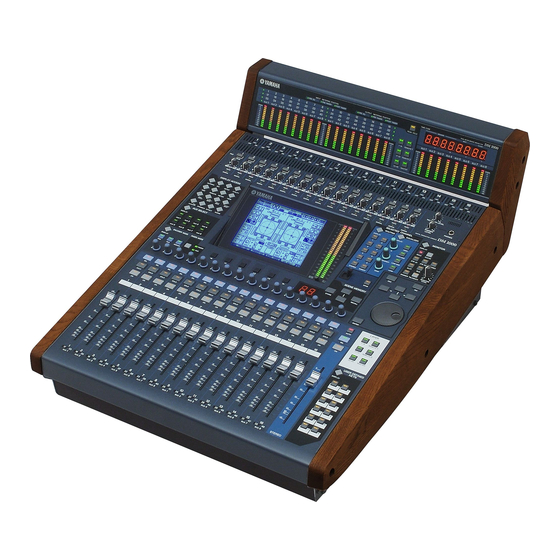
Yamaha Pro Audio global website Yamaha Pro Audio global website http://www.yamahaproaudio.com/ Package Contents • DM1000 Digital Production Console • CD-ROM • Power cord • This manual • Studio Manager Installation Guide Optional Extras • MB1000 Peak Meter Bridge • SP1000 Wooden Side Panels •... -
Page 7: New Functions In Dm1000 Version 2
New Functions in DM1000 Version 2 The following functions have been added to the DM1000 as part of the upgrade of the firm- ware from version 1.0 to version 2.0. Control Surface • Encoder mode now features an assignable function, ALT LAYER, which enables you to con- trol the channel level for all 32 channels without switching between layers. -
Page 8: Other Functions
Tools Surround Pan settings. → page 216 • Yamaha’s proprietary Advanced DAW protocol has been added to Nuendo, Cubase SX, and General DAW. This enables you to control these devices using the DM1000’s SELECTED CHANNEL section. (Controllable functions vary depending on the DAW software and ver- sion you are using.) -
Page 9: Table Of Contents
Contents Welcome ........13 Control Surface & Rear Panel ....15 Control Surface . - Page 10 Contents Aux Sends ........93 Aux Out 1–8 ............93 Setting Aux Out 1–8 from the Control Surface .
-
Page 11: Contents
15 Libraries ........173 About the Libraries ..........173 General Library Operation . - Page 12 Contents Appendix A: Parameter Lists ..... . 293 USER DEFINED KEYS ..........293 USER DEFINED KEYS Initial Assignments .
-
Page 13: Welcome
1 Welcome Thank you for choosing the Yamaha DM1000 Digital Production Console. The compact DM1000 Digital Console features 24-bit/96 kHz digital audio processing without compromise, as well as 48-channel simultaneous mixing. The DM1000 covers a broad range of needs and applications, including multi-track recording, 2-channel mix- down, and cutting-edge surround sound production. -
Page 14: Surround Sound
Chapter 1—Welcome ■ Channel Configuration • Simultaneous mixing of up to 48 Input Channels. Group multiple channels and pair channels for stereo. • 8 Bus Outs and 8 AUX Sends. Buses 1-8 can be routed to Stereo Buses for use as Group Buses. -
Page 15: Control Surface & Rear Panel
2 Control Surface & Rear Panel Control Surface DISPLAY ACCESS Section (p. 19) +48V +48V +48V +48V 20dB 20dB 20dB 20dB 20dB GAIN GAIN GAIN GAIN PEAK PEAK PEAK PEAK PEAK SIGNAL SIGNAL SIGNAL SIGNAL SIGNAL DISPLAY ACCESS AUTOMIX SETUP UTILITY MIDI REMOTE... -
Page 16: Ad Input Section
Yamaha does not sell such a cover. If you fabricate and attach your own cover, make sure that the mounting screws do not extend more than 10 mm into the front panel. -
Page 17: Channel Strip Section
Channel Strip Section A Encoders 1–16 These rotary Encoders adjust the channel parameter settings. Depending on the button selected in the ENCODER MODE section (see page 18), the Encoders will adjust the chan- nel pan setting (when the ENCODER MODE [PAN] button indicator is lit), the AUX Send level (when the ENCODER MODE [AUX] button indicator is lit), or any parameter (when the ENCODER MODE [ASSIGN] button indicator is lit). - Page 18 Chapter 2—Control Surface & Rear Panel AUX SELECT Section A [DISPLAY] button This button displays an Aux-related page (see page 99). B [AUX 1]–[AUX 8] buttons These buttons select an Aux Send. When you press a button to select an AUX Send, the cor- responding button indicator lights up.
-
Page 19: Display Access Section
DISPLAY ACCESS Section A [AUTOMIX] button This button displays an Automix page, enabling you to make Automix settings (see page 187). B [DIO] button This button displays a DIO page, enabling you to make digital I/O settings (see page 55). C [SETUP] button This button displays a Setup page, enabling you to make the DM1000 internal settings. -
Page 20: Display Section
Chapter 2—Control Surface & Rear Panel N [DYNAMICS] button This button displays a Dynamics page, enabling you to control channel gates and compres- sors (see page 65). O [EFFECT] button This button displays an Effect page, enabling you to edit the internal effects processors and use optional plug-in cards (see page 159). -
Page 21: Selected Channel Section
SELECTED CHANNEL Section A ROUTING [DISPLAY] button This button displays a Routing page, enabling you to route selected channels to the desired Bus, and adjust the level of the signals routed from Buses 1–8 to the Stereo Bus (see page 71 and 85). -
Page 22: Layer Section
Chapter 2—Control Surface & Rear Panel LAYER Section A [1-16]/[17-32]/[33-48] buttons These buttons select an Input Channel Layer. The channel strips control Channels 1–16, 17–32, or 33–48, depending on the button selected here. (See page 33 for more information on Layers.) B [REMOTE 1]/[REMOTE 2] buttons These buttons select the Remote Layer, which can be used to control external devices, including DAWs. -
Page 23: Data Entry Section
USER DEFINED KEYS Section A [DISPLAY] button USER DEFINED KEYS This button displays a User Def page, enabling you to assign functions to but- DISPLAY tons 1–12 (see page 274). B [1]–[12] buttons These buttons perform the functions assigned in the User Def pages. Data Entry Section A Parameter wheel This control adjusts the parameter values shown on the display. -
Page 24: Monitor Section
Chapter 2—Control Surface & Rear Panel MONITOR Section A [DISPLAY] button This button displays a Monitor page, enabling you to adjust monitor settings (see page 119 and 136). B [SOLO] indicator This indicator flashes when a single or multiple channels are soloed. C [CLEAR] button This button “unsolos”... -
Page 25: Rear Panel
Rear Panel OMNI POWER AC IN METER SMPTE IN CONTROL Power Section (p. 27) AD Input and Output Section OMNI A INPUT connectors 1–16 These balanced XLR-3-31-type con- nectors accept line-level and micro- phone signals. The nominal signal level ranges from –60 dB through +4 dB. B OMNI IN connectors 1–4 These balanced XLR-3-31-type connectors accept line-level signals. -
Page 26: Remote Connector
This 9-pin D-Sub connector is used to remotely control external equipment that supports the Yamaha AD8HR, AD824 and Sony P2 Protocol (remote control commands that are used on TASCAM DA-98HR and other professional video recorders). Use a reverse cable to connect an AD8HR/AD824, and use a straight cable to connect a P2 Protocol device. -
Page 27: Power Section
G WORD CLOCK OUT connector This BNC connector outputs a wordclock signal from the DM1000 to a connected external device. H WORD CLOCK IN connector This BNC connector inputs a wordclock signal from a connected external device to the DM1000. I 2TR OUT DIGITAL AES/EBU 1 This XLR-3-31-type connector outputs AES/EBU format digital audio. -
Page 28: Installing An Optional Card
Chapter 2—Control Surface & Rear Panel Installing an Optional Card Visit the following Yamaha Pro Audio web site to ensure that the card you are installing is supported by the DM1000. Also, verify the number of cards (including other Yamaha or third-party cards) that can be installed in the unit. -
Page 29: Operating Basics
3 Operating Basics This chapter describes basic operations on the DM1000, including how to use the display and operate the controls on the top panel. About the Display The top panel display indicates various parameters that you must set before you can operate the DM1000. -
Page 30: Selecting Display Pages
Chapter 3—Operating Basics MIDI indicator This indicator appears when the DM1000 is receiving MIDI data via the MIDI IN port, USB port, REMOTE connector, or an installed MY8-mLAN card. Surround mode indicator This indicator identifies the currently-selected Surround mode (ST=stereo, 3-1, 5.1, or 6.1) (see page 125). -
Page 31: Display Interface
• Selecting the next page in a page group: Press the button you selected in Step 1 repeatedly. This enables you to select a page that has a hidden tab. • To select the previous page in a page group: Press and hold down the button you selected in Step 1. -
Page 32: Title Edit Window
Chapter 3—Operating Basics Confirmation Messages For certain functions, the DM1000 prompts you for confirmation before executing the functions, as shown here. Move the cursor to YES and press [ENTER] to execute the function, or move the cursor to NO and press [ENTER] to cancel. If you take no action for awhile, the confirmation window closes automatically and the function is not executed. -
Page 33: Selecting Layers
Selecting Layers Input Channels and Output Channels (Bus Outs & Aux Outs) are arranged into layers, as illustrated below. There are six layers altogether. Input Channel Layer 1–16 Input Channel Layer 17–32 Input Channel Layer 33–48 The currently-selected layer determines the function of the channel strip Encoders, [SEL] buttons, [SOLO] buttons, [ON] buttons, and fad- ers. -
Page 34: Selecting Channels
Chapter 3—Operating Basics Selecting Channels The SELECTED CHANNEL controls enable you to edit main mix parameters for a channel selected from the Input Channels and Output Channels (Aux Outs, Bus Outs, and Stereo Out). To select a channel for editing using the SELECTED CHANNEL controls, follow the steps below: 1 Press the corresponding LAYER button to select a layer that includes the desired channel (see... -
Page 35: Selecting Fader Modes
Selecting Fader Modes The function of channel faders (1–16) depends on the selected Layer and Fader mode. 1 Select a layer that includes the desired channel (see page 33). 2 Press the FADER MODE [FADER/AUX] button to select a Fader mode. -
Page 36: Selecting Encoder Modes
Chapter 3—Operating Basics Selecting Encoder Modes The function of Encoders (1–16) depends on the selected Layer and Encoder mode. 1 Select a layer that includes the desired channel (see page 33). 2 Press the corresponding ENCODER MODE button to select an Encoder mode. •... -
Page 37: Assigning Parameters To The Encoder Mode [Assign] Button
Assigning Parameters to the ENCODER MODE [ASSIGN] button Assigning Parameters to the ENCODER MODE [ASSIGN] button While the ENCODER MODE [ASSIGN] button indicator is lit, you can use Encoders 1–16 to control a parameter assigned to the [ASSIGN] button. Follow the steps below to assign a parameter to the [ASSIGN] button. - Page 38 Chapter 3—Operating Basics • Assignable Encoder Mode Parameter List No Assign Attenuator Input Patch Insert In Patch Insert Out Patch Direct Out Phase: Insert On Aux pre/post Delay On Delay Time Delay FB.Gain Delay Mix EQ On EQ Type EQ Low Q EQ Low F EQ Low G EQ Low-Mid Q...
-
Page 39: Metering
Metering This section describes how to check Input and Output Channel levels using the Meter pages or an optional MB1000 Peak Meter Bridge. 1 Press the DISPLAY ACCESS [METER] button repeatedly until the Meter | Posi- tion page appears. This page enables you to set the metering position for Input and Output Channels. INPUT section This section enables you to select the metering position for Input Channel signals. - Page 40 Chapter 3—Operating Basics - Stereo page This page displays the Stereo Out or Control Room Monitor output level. Tip: You can also select the CH1-32 page, the CH33-48 page, or the Master page using the LAYER buttons. In this case, if an optional MB1000 Peak Meter Bridge is installed, the Peak Meter Bridge displays the same signal meters in unison with the DM1000 meters.
- Page 41 5 If you selected the Stereo page, use the METER MODE parameter to select one of the following two metering signal types: • C-R ...Control Room Monitor output signal • STEREO...Stereo Out signal This parameter setting affects the meters on the Meter | Master page, the ST meter on the Stereo page, and the stereo meter on the right side of the display.
- Page 42 Chapter 3—Operating Basics DM1000 Version 2—Owner’s Manual...
-
Page 43: Connections And Setup
4 Connections and Setup This chapter explains how to connect and set up your DM1000. Connections The following section explains three typical ways to connect the DM1000 to external equip- ment, although there are numerous others. ■ Configuring an analog 32-channel mixing system Synthesizer MUSIC PRODUCTION SYNTHESIZER Real-time External Control Surface... - Page 44 Chapter 4—Connections and Setup ■ Configuring a recording system with a hard disk recorder HDR (Hard Disk Recorder) WORD CLOCK OUT connector Effects processor SLOT 1 OMNI IN connector OMNI OUT connector Synthesizer MUSIC PRODUCTION SYNTHESIZER Integrated Sampling Sequencer Modular Synthesis Plug-in System Real-time External Control Sur face SONG SCENE INPUT connector...
- Page 45 ■ Configuring a recording system that uses a DAW (Digital Audio Workstation) MIDI interface Audio interface WORD CLOCK OUT MY-16AT etc. Effects processor SLOT 1 OMNI IN connector OMNI OUT connector Synthesizer MUSIC PRODUCTION SYNTHESIZER Real-time External Control Surface Integrated Sampling Sequencer Modular Synthesis Plug-in System SONG SCENE INPUT connector...
-
Page 46: Wordclock Connections And Settings
Chapter 4—Connections and Setup Wordclock Connections and Settings About wordclock Digital audio equipment must be synchronized when digital audio signals are transferred from one device to another. Even if both devices use identical sampling rates, digital signals may not transfer correctly, or audible noise or unwanted clicks may occur if the digital audio processing circuits inside each digital audio device are not synchronized with each other. - Page 47 If the external devices do not have wordclock in and out connectors, you can use the clock information included in the digital audio signals. In this case, digital audio signals and wordclock signals are transferred via the 2TR OUT DIGITAL and 2TR IN DIGITAL jacks or via the digital I/O cards installed in the rear panel slots.
- Page 48 Chapter 4—Connections and Setup The source select button indicators are explained below: A usable wordclock signal is present at this input, and it is in sync with the current DM1000 internal clock. No wordclock signal is present at this input. A usable wordclock signal is present at this input, but it is out of sync with the current DM1000 internal clock.
-
Page 49: Input And Output Patching
Input and Output Patching The DM1000 is designed to enable you to patch (assign) signals to Inputs and Outputs. This section explains how to view the signals patched to Inputs and Outputs and change the assignment. Tip: If the data from a connected instrument fails to be input, or if you are unable to monitor an OMNI OUT, check the I/O patching, as explained below: Patching Input Channels By default, the Input Channels are patched as follows:... - Page 50 Chapter 4—Connections and Setup • 2D2L & 2D2R ... 2TR DIGITAL IN 2 (L/R) • BUS1–8... Bus 1–8 Outputs • AUX1–8 ... Aux Send 1–8 Outputs 2 Use the cursor buttons to move the cursor to a patch parameter ( which you want to change the assignment, and rotate the Parameter wheel or press the [INC]/[DEC] buttons to modify the patching.
- Page 51 • SURR XXX (“XXX” is a channel name)..Surround Monitor Outs • CR-L/CR-R... Control Room Monitor signals • CAS BUS1–BUS8 ... Bus 1–8 Cascade Outs • CAS AUX1–AUX8 ... Aux Send 1–8 Cascade Outs • CAS ST-L/ST-R... Stereo Bus Cascade Outs •...
- Page 52 Chapter 4—Connections and Setup DM1000 Version 2—Owner’s Manual...
-
Page 53: Analog I/O & Digital I/O
5 Analog I/O & Digital I/O This chapter describes the DM1000’s analog and digital input/output connectors as well as the basic operations involving the digital I/Os. Analog Inputs & Outputs AD Input Section The DM1000’s rear panel features Input connectors 1–16, which enable you to connect microphone and line-level sources, and OMNI IN connectors, which enable you to connect line-level sources. -
Page 54: Digital Inputs & Outputs
COAXIAL SLOT 1–2 These slots allow you to install optional mini-YGDAI (Yamaha General Digital Audio Inter- face) I/O cards. These cards offer AD/DA conversion, and various analog I/O options and digital I/O interfaces in all the popular digital audio interconnect formats, including AES/EBU, ADAT, and Tascam. -
Page 55: Converting Sampling Rates Of Signals Received At 2Tr Digital Inputs
2. These cards support 24-bit/96 kHz in Double Channel mode. (Separate 96 kHz wordclock required.) 3. This card is identical to the MY8-AE96, except that it features a sampling rate converter. See the Yamaha Professional Audio Web site at the following URL for up-to-date news on I/O cards: <http://www.yamahaproaudio.com/>. - Page 56 You can turn the sampling rate converters of the digital I/O cards on or off in pairs (odd & even channels, in this order). Note: The sampling rate converter is available only on the Yamaha MY8-AE96S Digital I/O card. If you have installed other types of I/O cards in the slots, or if no cards are installed in the DM1000, the buttons in the SRC sections are disabled.
-
Page 57: Monitoring Digital Input Channel Status
4 Use the cursor buttons to move the cursor to any two-channel button in the SRC sections ( ), then press [ENTER]. The sampling rate converter for the selected 2-channel input turns on or off. When on, the sampling rate of the received digital audio is converted to the DM1000’s current sampling rate. - Page 58 Chapter 5—Analog I/O & Digital I/O CATEGORY Indicates the status of “Category Code Bit” included in the IEC958 Part 2 (S/PDIF-Con- sumer) format. This parameter can display the following values: Parameter values General Laser Optical D/D Conv Magnetic D.Broadcast Instruments A/D Conv A/D Conv with(C) Solid Memory...
-
Page 59: Dithering Digital Outputs
Dithering Digital Outputs When digital audio is transferred to lower-resolution systems, truncated bits may generate unpleasant noise. To cancel the audible effect of this noise, a small complement of noise is intentionally added to the digital outputs. This process is called “dithering.” On the DM1000, you can dither the 2TR Digital Outputs and Slot Outputs. - Page 60 Chapter 5—Analog I/O & Digital I/O 3 Press the DISPLAY ACCESS [DIO] button, then press the [F2] button. The DIO | Format page appears. 4 Use the cursor buttons to move the cursor to an IN/OUT parameter field ), and rotate the Parameter wheel or press the [INC]/[DEC] buttons to set the data transfer format.
-
Page 61: Input Channels
6 Input Channels This chapter describes how to adjust the DM1000’s Input Channel parameters. About Input Channels The input Channel section enables you to adjust the level and tone of the signals input to the DM1000 and route the signals to Bus 1–8, Stereo Bus, and Aux Out 1–8. The following diagram illustrates the Input Channel signal flow. - Page 62 Chapter 6—Input Channels • PAN This section enables you to adjust the pan setting of the signals routed from the Input Chan- nels to the Stereo Bus. You can also apply the pan setting to a pair of Bus channels. If the internal Surround Sound setting is activated, the Surround Pan settings for 3-1, 5.1, and 6.1 channels are available (see page 125).
-
Page 63: Setting The Input Channels From The Display
Setting the Input Channels from the Display To set the Input Channel parameters, you can either move the cursor to the desired param- eter on the display and change the value, or operate the desired button or control on the top panel to directly change the setting. - Page 64 Chapter 6—Input Channels The parameters on these three pages (and the procedure for setting them) are the same. DELAY SCALE The following buttons determine the units of the delay value shown below the msec value. • meter ... Units are set to meters. •...
-
Page 65: Gating Input Channels
Gating Input Channels To set the Input Channel gates, use the [SEL] buttons to select the desired Input Channel, then press the DISPLAY ACCESS [DYNAMICS] button, then the [F1] button. The Dynam- ics | Gate Edit page appears. KEYIN SOURCE Select one of the following buttons to determine the trigger source for the cur- rently-selected Input Channel’s gate. -
Page 66: Compressing Input Channels
Chapter 6—Input Channels Compressing Input Channels To set the Input Channel compressors, use the [SEL] buttons to select the desired Input Channel, then press the DISPLAY ACCESS [DYNAMICS] button, then the [F3] button to display the Dynamics | Comp Edit page. POSITION Use the Parameter wheel, or the [INC]/[DEC] buttons to select the position of the com- pressor within the channel from the following options:... -
Page 67: Attenuating Input Channels
Attenuating Input Channels To set the attenuator for each channel, press the SELECTED CHANNEL EQUALIZER [DISPLAY] button repeatedly until the page listed below that contains the desired channels appears. - ATT 1-16 page This page enables you to set the attenuators for Input Channels 1–16. - ATT 17-32 page This page enables you to set the attenuators for Input Channels 17–32. - Page 68 TYPE. TYPE Selects the type of EQ. TYPE I is the EQ type used on legacy Yamaha 02R series digital mixing consoles. TYPE II is a newly developed algorithm. Determines the amount of pre-EQ signal attenuation in dB. It is the same Attenuator parameter that appears on the EQ | ATT 1-16, ATT 17-32, and ATT 33-48 pages.
- Page 69 Setting the Input Channels from the Display LOW, L-MID, H-MID, HIGH sections These sections contain the Q, Frequency (F), and Gain (G) parameters for the four bands. These parameter values range as follows: Parameter HPF, 10.0 to 0.10 (41 steps), L.SHELF Frequency 21.2 Hz to 20.0 kHz (120 steps per 1/12 octave) Gain...
-
Page 70: Panning Input Channels
Chapter 6—Input Channels Panning Input Channels Input Channels can be panned in the range of L63 through CENTER to R63. To pan each channel, press the [PAN/SURROUND] button repeatedly until one of the following pages that contains the desired channels appears. - Pan1-32 page This page enables you to set the pan for Input Channels 1–32. -
Page 71: Routing Input Channels
Routing Input Channels You can route each Input Channel to the Stereo Bus, Bus 1–8, or its own Direct Out. With the default setting, signals are routed only to the Stereo Bus. However, you can patch signals to a single or multiple destinations, if necessary. 1 Press the SELECTED CHANNEL ROUTING [DISPLAY] button repeatedly until the page listed below that contains the desired channels appears. -
Page 72: Viewing Input Channel Settings
Chapter 6—Input Channels D button When this button is turned on, the currently-selected Input Channel is routed to its Direct Out. See page 115 for more information on the Direct Out. ALL STEREO button This button turns on the S button for all channels on the page. ALL BUS button This button turns on the Bus buttons 1–8 for all channels on the page. - Page 73 Setting the Input Channels from the Display Meters These meters indicate the signal levels of the currently-selected Input Channel and its available pair partner. (Phase) section You can reverse the signal phase of the currently-selected Input Channel. (See page 63 for more information.) DELAY section This section enables you to set the currently-selected channel’s Delay function.
- Page 74 Chapter 6—Input Channels BUS ROUTING/FOLLOW PAN section • BUS ROUTING... This section enables you to select a destination Bus for the • FOLLOW PAN ... This button determines whether the Input Channel’s Pan set- AUX section • AUX ... These controls set the currently-selected Input Channel’s Aux Meter section •...
-
Page 75: Setting The Input Channels From The Control Surface
Setting the Input Channels from the Control Surface Setting the Input Channels from the Control Surface You can use the faders, Encoders, [SEL] buttons, and various buttons and controls in the SELECTED CHANNEL section on the top panel to directly control most parameters for Input Channels. -
Page 76: Pairing Input Channels
Chapter 6—Input Channels 4 Use the EQUALIZER [Q], [FREQUENCY], and [GAIN] controls to adjust the Q, frequency, and gain of the band selected in Step 3. See page 68 for more information on EQ. Tip: • Pressing and holding down the button selected in Step 3 resets the corresponding band gain. •... - Page 77 ■ Pairing Channels by Using the [SEL] Buttons 1 While pressing and holding down the [SEL] button for one of the channels you wish to pair, press the [SEL] button for the adjacent channel. (The paired channel numbers should be odd and even in this order). Note: The settings of the first channel are copied to the second channel and the channels are paired if the Pair Confirmation check box on the Preference1 page is not checked (default).
- Page 78 Chapter 6—Input Channels ■ Pairing Input Channels Using the Display 1 Press the [PAIR/GROUP] button repeatedly until the Pair/Grup | Input page appears. The parameters on this page are described below: PAIR MODE Determines how channels are paired. STEREO/MONO x2 buttons These buttons turn pairs on or off.
-
Page 79: Naming Input Channels
Naming Input Channels By default, Input Channels are named CH1, CH2, etc. You can change these names if nec- essary. For example, it may be helpful for mixdown if you name a particular Input Channel with the type of musical instrument connected to the corresponding input jack. 1 Press the DISPLAY ACCESS [INPUT PATCH] button repeatedly until the In Patch | CH Name page appears. -
Page 80: Using Ms Stereo Microphone
Chapter 6—Input Channels Using MS Stereo Microphone The MS system is a type of stereo recording that uses two microphones; mono-directional M (Middle) and bi-directional S (Side) microphones. An M microphone picks up main sig- nals, and an S microphone picks up directional signals. These two signals are decoded by calculating a sum (M plus S) and a difference (M minus S), and are recorded to L and R channels. -
Page 81: Bus Outs
7 Bus Outs This chapter describes how to adjust the DM1000’s Stereo Out and Bus Out parameters. About Stereo Out The Stereo Out section receives Input Channel and Bus Out 1–8 signals, mixes them into two channels, processes them using on-board EQ, compressor, etc., then routes them to two channel output connectors. -
Page 82: Bus Out 1-8
Chapter 7—Bus Outs Bus Out 1–8 The Bus Out 1–8 section mixes signals routed from Input Channels to the specified buses, processes them using on-board EQ, compressor, etc., then routes them to the specified out- put connectors or I/O cards. The following diagram illustrates the Bus Out signal flow. -
Page 83: Setting The Stereo Out And Bus Out 1-8 From The Display
Setting the Stereo Out and Bus Out 1–8 from the Display Setting the Stereo Out and Bus Out 1–8 from the Display To set the Stereo Out and Bus Out 1–8 parameters, you can either move the cursor to the desired parameter on the display and change the value, or operate the desired button or control on the top panel. - Page 84 Chapter 7—Bus Outs Compressing the Stereo Out and Bus Outs To set the Stereo Out and Bus Out 1–8 compressors, press the [DYNAMICS] button, then the [F3] button to display the Dynamics | Comp Edit page, and use the [SEL] buttons or faders to select the Stereo Out or Bus Out 1–8.
- Page 85 Setting the Stereo Out and Bus Out 1–8 from the Display Routing Bus Out 1–8 Signals to the Stereo Bus You can patch Bus Out 1–8 signals to Outputs and Slots 1/2, as well as to the Stereo Bus. You can adjust the level and pan settings of the signals routed to the Stereo Bus for each bus.
- Page 86 Chapter 7—Bus Outs Viewing the Stereo Out and Bus Out Settings You can view and adjust parameter settings for the currently-selected Stereo Out or Bus Out on the View | Parameter and Fader pages. ■ Viewing the Compressor and EQ Settings To display the View | Parameter page, use the corresponding [SEL] button or fader to select the desired bus, then press the DISPLAY ACCESS [VIEW] button, then the [F1] button.
- Page 87 Setting the Stereo Out and Bus Out 1–8 from the Display Fader This fader adjusts the Stereo Out output levels, and links with the [STEREO] fader. The fader knob is highlighted when the fader is set to 0.0 dB. • Bus Out (1–8) Fader page ON/OFF This button turns the currently-selected Bus Out (1–8) on or off, and links with the [ON] (9–16) button in the Master layer.
-
Page 88: Setting The Stereo Out And Bus Out 1-8 From The Control Surface
Chapter 7—Bus Outs Setting the Stereo Out and Bus Out 1–8 from the Control Surface You can use the faders, Encoders, [SEL] buttons, and various buttons and controls in the SELECTED CHANNEL section on the top panel to directly control certain parameters for the Stereo Out and Bus Out 1–8. -
Page 89: Pairing Buses Or Aux Sends
Pairing Buses or Aux Sends You can pair adjacent odd-even (in this order) buses or Aux Sends for stereo operation. Paired bus and Aux Send linked parameters and non-linked parameters (that are available for independent controls) are listed below: Linked parameters [SEL] buttons Fader Channel on/off... -
Page 90: Attenuating Output Signals
Chapter 7—Bus Outs Attenuating Output Signals To attenuate the DM1000’s output signals, display the EQ | Out Att page and adjust the Ste- reo Out and Bus Out 1–8 attenuators individually. If necessary, you can also select Output and I/O card channels and specify the amount of attenuation. -
Page 91: Naming The Stereo Out And Bus Outs
Naming the Stereo Out and Bus Outs You can change the default Bus names (BUS1, AUX4, STEREO, etc.). It may be convenient to name the buses “Monitor Out” or “Effect Send,” for example, so that you can easily iden- tify the signal type. 1 Press the DISPLAY ACCESS [OUTPUT PATCH] button repeatedly until the Out Patch | CH Name page appears. - Page 92 Chapter 7—Bus Outs DM1000 Version 2—Owner’s Manual...
-
Page 93: Aux Sends
8 Aux Sends This chapter describes how to control Aux Out 1–8. Aux Out 1–8 The Aux Out 1–8 section mixes signals routed from the Input Channels to the correspond- ing Aux Sends, processes them using on-board EQ, compressor, etc., then routes them to the specified internal effects processors, output connectors or I/O card connectors. -
Page 94: Setting Aux Out 1-8 From The Control Surface
Chapter 8—Aux Sends Setting Aux Out 1–8 from the Control Surface You can use the faders, Encoders, [SEL] buttons, and various buttons and controls in the SELECTED CHANNEL section on the top panel to directly control certain parameters for Aux Out 1–8. Setting Levels To set Aux Out 1–8 levels, press the [MASTER] button in the LAYER section to select the Master layer, then move faders 1–8. - Page 95 Delaying Aux Outs To delay Aux Out 1–8 signals, press the [ /INS/DLY | Out Dly page appears. The parameters on this page (and the procedure for setting them) are the same as for Input Channels, except that this page does not have the MIX/FB.GAIN parameters (see page 63). Tip: You can also display the Out Dly page by pressing the [ then selecting the desired Aux Out (1–8) by pressing the corresponding [SEL] button or moving the fader.
-
Page 96: Viewing Aux Out Settings
Chapter 8—Aux Sends EQ settings To set the EQ for Aux Out 1–8, press the EQUALIZER [DISPLAY] button repeatedly to dis- play the EQ | EQ Edit page, and use the [SEL] buttons or faders to select Aux Out 1–8. The parameters on this page (and the procedure for setting them) are the same as for Input Channels (see page 68). - Page 97 ■ Viewing Faders and On/Off Parameters To display the View | Fader page, use the corresponding [SEL] button or fader to select the desired Aux Out (1–8), then press the DISPLAY ACCESS [VIEW] button, then the [F2] but- ton. • ON/OFF...This button turns the currently-selected Aux Out (1–8) on or off.
-
Page 98: Setting Aux Send Levels
Chapter 8—Aux Sends Setting Aux Send Levels You can adjust the level of signals routed from Input Channels to the corresponding Aux Out (1–8). To do this, you can either use the Encoders on the top panel or set the parameters on the screen. - Page 99 Setting Send Levels from the Display You can view multiple channels’ Aux Send levels on the screen and adjust them individually. 1 Press the AUX SELECT [AUX 1]–[AUX 8] buttons to select the Aux Sends. 2 Press the AUX SELECT [DISPLAY] button repeatedly until the page listed below that contains the desired channels appears.
- Page 100 Chapter 8—Aux Sends 3 Move the cursor to the FIXED or VARIABLE button in the MODE section for the currently-selected Aux Send to select a mode. • Fixed Mode In this mode, Aux Send levels are fixed at nominal (0.0dB). Also, channel ON/OFF buttons appear instead of the Send level rotary controls and PRE/POST buttons.
- Page 101 4 If you switched to Fixed mode in Step 3, the ON/OFF buttons turn on or off each Input Channel on or off for the currently-selected Aux Send. Note: In Fixed mode, the Aux On/Off parameters for paired Input Channels are not linked to each other.
-
Page 102: Viewing Aux Send Settings For Multiple Channels
Chapter 8—Aux Sends Viewing Aux Send Settings for Multiple Channels You can view and set parameters for all Aux Send 1–8, including setting levels and Pre/Post parameters. This is convenient when you wish to visually check all Aux Send settings or simultaneously adjust the levels of certain channels routed to Aux 1–8. - Page 103 Viewing Aux Send Settings for Multiple Channels 3 If you selected the PRE/POST button in Step 2, move the cursor to the desired Input Channel and Aux intersection, then press the [ENTER] button to change the signal source point. Note: You can switch between Pre and Post only for Aux Sends that are set to Variable mode. The “FIX”...
-
Page 104: Panning Aux Sends
Chapter 8—Aux Sends Panning Aux Sends You can pair adjacent odd-even (in this order) Aux Sends for stereo operation. This enables you to pan signals from Input Channels to paired Aux Sends. 1 Pair the desired two Aux Sends. (See page 89 for more information on pair- ing channels.) 2 Use the AUX SELECT [AUX 1]–[AUX 8] buttons to select one of the paired Aux Sends. -
Page 105: Excluding Certain Channels From Aux Sends (Mix Minus)
Excluding Certain Channels from Aux Sends (Mix Minus) 6 To link the Input Channel Pan setting with the Aux Send Pan setting, move the cursor to the INPUT PAN LINK ON/OFF button, then press [ENTER]. The pan positions on the Pan page are copied to the Aux pan setting, and the pan controls on both pages are linked. -
Page 106: Copying Channel Fader Positions To Aux Sends
Chapter 8—Aux Sends Copying Channel Fader Positions to Aux Sends While Aux Sends are in Variable mode, you can copy all Input Channel fader positions on one layer to the corresponding Aux Sends. This is convenient when you wish to send to the musicians monitor signals that have the same balance setting as the Stereo Out signals. -
Page 107: Soloing Aux Sends Using The [Aux 1]-[Aux 8] Buttons
Soloing AUX Sends using the [AUX 1]–[AUX 8] Buttons Soloing AUX Sends using the [AUX 1]–[AUX 8] Buttons You can turn the Solo function on and off using the AUX SELECT [AUX 1]–[AUX 8] but- tons, without having to switch to the Master layer. This is convenient when you wish to con- trol the Solo function for Aux Out 1-8 while adjusting the Aux Sends from Input Channels. - Page 108 Chapter 8—Aux Sends DM1000 Version 2—Owner’s Manual...
-
Page 109: Input & Output Patching
9 Input & Output Patching This chapter describes how to patch (assign) signal paths within the DM1000 to its inputs, outputs, and slot channels Input Patching Signals input at INPUT connectors 1–16, 2TR IN DIGITAL connectors 1–2, and Slot I/O cards are patched to Input Channels for use. - Page 110 Chapter 9—Input & Output Patching Input Patching from the Display 1 Press the DISPLAY ACCESS [INPUT PATCH] button repeatedly until the In Patch | In Patch page appears. Inputs and slot channels that are currently assigned to Input Channels are shown in the parameter boxes ( below: Parameter values...
- Page 111 Using the Encoders for Input Patching By default, you can also use the Encoders on the top panel to change the Input Patching. 1 Press the ENCODER MODE [ASSIGN] button. The button indicator lights up. By default, you can use the Encoders to change Input Patching while the [ASSIGN] button indicator is lit.
-
Page 112: Output Patching
Chapter 9—Input & Output Patching Output Patching The DM1000’s Stereo Out, Bus Out 1–8, Aux Out 1–8 signals can be patched to any outputs and slot channels. Patch example: By default, the following signal paths are patched to outputs and slot output channels: Output connectors and slot channels OMNI OUT connectors 1–8... - Page 113 Patching Omni Outs You can route the DM1000’s internal signals to OMNI OUT 1–12. 1 Press the DISPLAY ACCESS [OUTPUT PATCH] button repeatedly until the Out Patch | Omni Out page appears. The OMNI 1–12 parameter boxes ( eter indicators are explained below: Parameter values –...
- Page 114 Chapter 9—Input & Output Patching Patching the 2TR Digital Outputs You can route the DM1000’s internal signals to 2TR OUT DIGITAL connectors 1–2. 1 Press the DISPLAY ACCESS [OUTPUT PATCH] button repeatedly until the Out Patch | 2TR Out page appears. Signals assigned on the Omni Out page can also be assigned to the 2TR digital outputs.
-
Page 115: Patching Direct Outs
Patching Direct Outs Input Channel 1–48 signals can be directly patched to any outputs or slot outputs, as well as Bus Out 1–8 and Stereo Out. This patching is convenient when you wish to record each Input Channel signal to an individual track on a connected recorder. 1 Press the DISPLAY ACCESS [OUTPUT PATCH] button repeatedly until the Out Patch | Direct Out page appears. -
Page 116: Insert Patching
Chapter 9—Input & Output Patching Insert Patching The DM1000’s Input Channels and Output Channels (Stereo Out, Bus Out 1–8, Aux Out 1–8) feature independent Insert Ins and Outs. Inputs, outputs, slot channels, and internal effects processor inputs and outputs can be patched to the Output Channel Insert Ins and Outs. - Page 117 INSERT section • ON/OFF...This button turns Insert on or off. • OUT ...This parameter enables you to select outputs, slot channels, or internal effects inputs as the Insert Out destination. • IN...This parameter enables you to select inputs, slot channels, or internal effects outputs as the Insert In source.
- Page 118 Chapter 9—Input & Output Patching Viewing and Changing Insert In Patch You can view and also change the items patched to the Insert Ins of all Input Channels (or all Output Channels). This is useful when you wish to find out if multiple channels have the same patch.
-
Page 119: 10 Control Room Monitoring
10 Control Room Monitoring This chapter explains how to set up control room monitoring and use the Solo and Talkback functions on the DM1000. Control Room Monitor The DM1000 features the Control Room stereo signal path to feed the control room’s main monitors. -
Page 120: Solo Setup
Chapter 10—Control Room Monitoring Solo Setup For solo setup, press the MONITOR [DISPLAY] button repeatedly until the Monitor | Solo page appears. This page contains the following parameters: SOLO This parameter turns the Solo function on or off. By default, it is set to Enabled. MODE This parameter determines how the Solo function works. -
Page 121: Using The Solo Function
LISTEN This parameter determines the source of the Input Channel Solo signal: Pre Fader or After Pan. When Pre Fader is selected, turning on the PAN button below the Pre Fader option will solo the channel with the pan position specified by the Pan setting even if the source precedes the fader. -
Page 122: Using The Control Room Monitor
Chapter 10—Control Room Monitoring 3 To solo and monitor Input Channels, press the corresponding LAYER button to select a Layer that contains the desired channels, then press the channel [SOLO] buttons. The channel [SOLO] button indicators and the MONITOR [SOLO] indicator light up. Only the soloed Input Channel signals are fed to the Control Room Monitor outputs. -
Page 123: Sources
CONTROL ROOM DIMMER LEVEL This parameter determines the amount of attenuation applied to the Control Room Monitor signal by the Dimmer function when you press the MONITOR [DIMMER] button. The amount of attenuation can range from 0 dB to –96 dB. MONO This button switches the Control Room Monitor signal into mono. - Page 124 Chapter 10—Control Room Monitoring 1 Press the MONITOR [DISPLAY] button repeatedly until the Monitor | C-R/TB page appears. This page contains the following parameters: OUTPUT ASSIGN section The buttons in this section enable you to assign the Talkback mic signal to the desired outputs.
-
Page 125: Settings
11 Surround Functions This chapter describes surround panning, which determines how Input Channel signals are panned within and across the stereo field. It also describes the DM1000’s surround moni- toring capabilities, which enable you to monitor, in a surround sound environment, DM1000 surround mixes or surround sources input via the slots. - Page 126 Chapter 11—Surround Functions • 6.1 This mode uses seven channels that include six channels of 5.1 mode plus rear center. When you select one of these Surround modes, each surround channel is routed to the Buses specified on the Setup | Surr Bus page (see page 130). The following table shows the factory-default Surround Channel to Bus Out assignment in each Surround mode.
- Page 127 You can record each surround channel to a separate track to record surround panning. The following diagram is an example in which each channel signal in 5.1 Surround mode is recorded to digital MTR tracks. DM1000 SURROUND Input Channel 1 LFE LEVEL SURROUND Input Channel 2...
-
Page 128: Setting Up And Selecting Surround Pan Modes
Chapter 11—Surround Functions Setting Up and Selecting Surround Pan Modes To configure the surround environment, select 3-1, 5.1, or 6.1 Surround mode on the DM1000 and connect a multi-channel monitoring system to the DM1000. 1 Press the DISPLAY ACCESS [PAN/SURROUND] button repeatedly until the Pan/Surr | Surr Mode page appears. - Page 129 • 5.1 Surround • 6.1 Surround 3 Press the [ENTER] button. The confirmation window for changing the Surround mode appears. 4 Move the cursor to the YES button, then press [ENTER]. The DM1000 enters the selected Surround mode. 5 To link the Input Channel Pan setting with the stereo surround panning, move the cursor to the PAN/SURR LINK button, then press [ENTER].
- Page 130 Chapter 11—Surround Functions 6 To change the Surround Channel to Bus Out assignment, move the cursor to the SURR/BUS SETUP button, then press [ENTER]. The Setup | Surr Bus page appears. BUS1–BUS8 These parameters select channels to be assigned to the Bus Outs in 3-1, 5.1, and 6.1 Sur- round modes.
-
Page 131: Trajectory Patterns
Surround Panning from the Display You can set the surround pan parameters for each Input Channel from the display. 1 Make sure that the DM1000 is in one of the Surround modes, then press the [SEL] button of the channel for which you want to set surround pan. 2 Press the DISPLAY ACCESS [PAN/SURROUND] button repeatedly until the Pan/Surr | Ch Edit page appears. -
Page 132: St Link
Chapter 11—Surround Functions This parameter control sets the level of the LFE (Low Frequency Effects) Channel signal routed to the subwoofer, and appears only in 5.1 and 6.1 Surround modes. This parameter control determines how the Center signal is fed to the Left, Right, and Center channels. - Page 133 • ... The sound image moves between front and rear. • ... The sound image moves from front right to rear left. With this pattern, you can also fine-tune the trajectory by using the WIDTH, DEPTH, OFFSET ( • ... The sound image moves from front left to rear right. With this pattern, you can also fine-tune the trajectory using the WIDTH, DEPTH, OFFSET ( •...
- Page 134 Chapter 11—Surround Functions • ... The sound image moves between front and rear while tracing an arc. • ... The sound image moves while tracing a circle or oval. With this pat- 4 If necessary, fine-tune the trajectory by editing the WIDTH, DEPTH, OFFSET ), and OFFSET ( 5 To set the surround pan position, move the cursor to anywhere outside the parameter boxes, then rotate the Parameter wheel.
- Page 135 The following table shows how the sound images on two linked channels move when dif- ferent trajectory patterns and stereo link patterns are combined. A solid line indicates the movement of the selected channel, and a dotted line indicates the movement of the linked partner.
-
Page 136: Surround Monitoring
Chapter 11—Surround Functions Surround pan graphs These graphs display the trajectory patterns and the current pan positions for the Input Channels. Move the cursor to the desired channel’s graph, then rotate the Parameter wheel to adjust the pan settings along the selected trajectory pattern. Turning on the [GRAB] button enables you to use the Joystick to set the surround pan of the cur- rently-selected Input Channel. - Page 137 The following diagram shows an example of 5.1 Surround Monitor signals patched to OMNI OUTs 1–6. Use the following two buttons in the MONITOR section on the top panel to select the Sur- round Monitor signal source. If the MIX MONITOR SOURCES check box is checked in the Monitor | Surround page, you can select both buttons simultaneously.
-
Page 138: Surr. Mode
Chapter 11—Surround Functions Configuring Basic Surround Monitoring You can set basic parameters for Surround Monitor, including monitor matrix, Bass Man- agement, and monitor alignment. To do so, press the MONITOR [DISPLAY] button repeatedly until the Monitor | Surr Setup page appears. This page displays the basic parameter settings in the MONITOR FLOW section ( •... -
Page 139: Bass Management
The following diagram shows an example in 5.1 Surround mode and 3-1 Monitor Matrix mode. Note: You can patch the Surround Monitor Matrix channels to the output connectors. • BASS MANAGEMENT You can set the filter and attenuator settings for each Surround Monitor Channel using eight preset Bass Management modes. - Page 140 Chapter 11—Surround Functions About the Presets (1) DVD LFE80Hz This is a preset optimized for DVD-Video production. The LFE playback bandwidth is set up to 80 Hz. When using this preset, we recommend that you use an external device to apply an LPF (fc=80 Hz, –24 dB/oct) to the LFE master source.
- Page 141 [THXM] THX Music This preset is configured for DVD-Music production. Use this preset when mixing and/or monitoring multi-channel music content (including DVD-Audio and SACD). Only one parameter can be changed. The LFE gain (AMP) can be set to +10dB (default) or 0dB. Select the level that complies with the standards of the target media.
-
Page 142: Monitor Alignment
Chapter 11—Surround Functions • MONITOR ALIGNMENT You can adjust the Attenuator and Delay for each Surround Monitor Channel. This func- tion is primarily used to correct the level difference and delay time among speakers. Move the cursor to the ATT or DLY parameter in the MONITOR FLOW section. The MONITOR ALIGNMENT diagram is displayed in the area below the section. - Page 143 MUTE/SOLO section This section enables you to mute or solo Surround Monitor Channels for each Bus. • SOLO ...This button turns the Surround Monitor Solo function on or off. When this button is turned on, you can select speaker icons ) to solo certain Buses.
- Page 144 Chapter 11—Surround Functions Using the Oscillator for Surround Monitor The DM1000 features a dedicated Oscillator that enables you to check the output and sound of the surround sound speakers. You can send the Oscillator signal to certain speakers or to each speaker in turn.
- Page 145 4 Move the cursor to the ON/OFF button, then press the [ENTER] or [INC]/[DEC] buttons to turn the Oscillator on. The speaker specified in Step 2 outputs the Oscillator signal. If necessary, adjust the speaker volume balance in the MONITOR ALIGNMENT section on the Surr Setup page (see page 142).
- Page 146 Chapter 11—Surround Functions DM1000 Version 2—Owner’s Manual...
-
Page 147: Grouping Channels & Linking Parameters
12 Grouping Channels & Linking Parameters This chapter describes how to group faders or [ON] buttons for multiple channels and link the EQ or compressor parameters for simultaneous operation. Grouping & Linking On the DM1000, you can group faders or [ON] buttons for multiple Input Channels or multiple Output Channels (Bus Outs 1–8, Aux Outs 1–8) and link the EQ or compressor parameters. -
Page 148: Using Fader Groups And Mute Groups
Chapter 12—Grouping Channels & Linking Parameters Using Fader Groups and Mute Groups Follow the steps below to group faders or [ON] buttons for Input Channels or Output Channels (Bus Outs 1–8, Aux Outs 1–8). 1 Press the DISPLAY ACCESS [PAIR/GROUP] button repeatedly until one of the pages that contains the desired group and channels appears. - Page 149 2 Press the up ( ) or down ( ) button to select a group. Example: Fader group C is selected. 3 Press the [SEL] button for a channel you wish to add to the group. The selected channel is marked with “ Example: Input Channels 1–6, and 13–14 have been added to Fader group C.
-
Page 150: Using Fader Group Master
Chapter 12—Grouping Channels & Linking Parameters 7 To use a mute group, press one of the [ON] buttons for the grouped channels. All channels in the group switch their on/off status. Note: • While a mute group is enabled, you cannot turn a subset of the grouped channels on or off. •... - Page 151 4 Use the cursor buttons to select parameters, then use the Parameter wheel, INC/DEC buttons, or [ENTER] button to set the parameters. • INPUT/OUTPUT FADER MASTER...When this check box is checked, you can set the • ALL NOMINAL...This button resets the master levels for all Fader groups to nom- inal.
-
Page 152: Simultaneously
Chapter 12—Grouping Channels & Linking Parameters Using Mute Group Master In addition to the Mute Group function that links the operation of channel [ON] buttons, the DM1000 features a Mute Group Master function that enables you to mute grouped channels using the Master Mute buttons in a manner similar to using a mute group on an analog mixing console. - Page 153 Linking EQ and Compressor Parameters - Out EQ page This page enables you to set EQ links (e–h) for Bus Outs (1–8) and Aux Outs (1–8). - In Comp page This page enables you to set Compressor links (i–l) for Input Channels. - Out Comp page This page enables you to set Compressor links (m–p) for Bus Outs (1–8) and Aux Outs (1–8).
- Page 154 Chapter 12—Grouping Channels & Linking Parameters 2 Press the up ( ) or down ( ) cursor button to select a link to which you want to add channels. 3 Press the [SEL] button for a channel you wish to add to the EQ or Compressor link.
-
Page 155: 13 Internal Effects
13 Internal Effects This chapter describes how to use the DM1000’s internal effects processors. About the Internal Effects The DM1000 features four internal multi-effects processors that can be used via Aux Sends or by inserting them into specific channels. These effects processors offer numerous types of effects, including reverbs, delays, modu- lation-based effects, combination effects, and multi-channel effects designed especially for use with surround sound. -
Page 156: Using Effects Processors Via Aux Sends
Chapter 13—Internal Effects Using Effects Processors via Aux Sends You can use effects processors via Aux Sends by patching effects processor inputs to Aux Outs, and effects processor outputs to Input Channels. 1 Recall an effect program you wish to use. See page 177 for more information on recalling effect programs. - Page 157 • FX1-1–FX4-2 ...Other effects processor outputs You cannot select outputs FX1–3 to FX1–8. In addition, you cannot select the output of the effects processor you are cur- rently using. To use the internal effects processors via Aux Sends, select Aux 1–8 (in most cases). You can patch a different signal to the other input of 2-in/2-out effect programs.
-
Page 158: Inserting The Internal Effects Into Channels
Chapter 13—Internal Effects Inserting the Internal Effects into Channels You can insert the internal effects into certain Input Channels or Output Channels (Bus Outs 1–8, Aux Outs 1–8, Stereo Out). Note: If effects are inserted in channels, you cannot use those effects via Aux Sends or insert them into other channels. -
Page 159: Editing Effects
Editing Effects To edit effect programs recalled to the internal Effects processors 1–4, press the DISPLAY ACCESS [EFFECT] button repeatedly until the Edit page for the effects processor you wish to edit appears. Effects processors 1–4 correspond to the following pages: •... - Page 160 Chapter 13—Internal Effects When you turn on the SYNC parameter, the DM1000 recalculates the delay time or modulation frequency based on the TEMPO parameter value (tempo) and the NOTE parameter value (note). For example, if the TEMPO parameter is set to 120BPM and the NOTE parameter is set to one eighth note, turning on the SYNC parameter sets the delay time to 250 msec and the modulation frequency to 0.25 Hz.
-
Page 161: About Surround Effects
About Surround Effects The effects types available for Effects processor 1 include surround effects that support 5.1-channel (AUTO PAN 5.1, CHORUS 5.1, etc.). Surround effects are multi-channel effects that feature up to six inputs and six outputs, and enable you to create the effect of the sound image moving or circling back and forth and left to right, and to process up to six channel input signals simultaneously. -
Page 162: About Plug-Ins
For details on using plug-ins, refer to the owner’s manual that came with the plug-in card. As of July 2004, the DM1000 supports the following plug-in cards. Visit the Yamaha web site for the latest information on compatible plug-in cards. -
Page 163: 14 Scene Memories
14 Scene Memories This chapter describes Scene memories, which store DM1000 mix and effects settings. About Scene Memories Scene memories enable you to store a snapshot of DM1000 channel mix settings and inter- nal effects processor settings as a “Scene” in a special memory area. There are 99 Scene memories, and you can recall any Scene using the display pages or the controls on the top panel. -
Page 164: About Scene Numbers
Chapter 14—Scene Memories About Scene Numbers Scene memories are numbered with #U or from #0 through #99. You can store Scenes in Scene memories #1–99. When you recall a Scene, the Scene memory number (Ud, 00–99) appears on the Scene memory display and at the top of the display page. Scene memory #0 (#00 on the Scene memory display) is a special read-only memory that contains the default settings of all mix parameters. -
Page 165: Storing And Recalling Scenes
Storing and Recalling Scenes You can store and recall Scenes by pressing the buttons on the top panel or using the dedi- cated Scene memory page on the display. Note: • When you store Scenes, make sure that there are no settings in the Edit Buffer that you do not want to store. - Page 166 Chapter 14—Scene Memories Storing and Recalling Scenes Using the Scene Memory Page On the Scene Memory page, you can store, recall, write-protect, delete, and edit the titles of Scenes. 1 Adjust the mix parameters on the DM1000 to the conditions you wish to store as a Scene.
-
Page 167: Auto Scene Memory Update
PATCH LINK OUTPUT This indicates the Output Patch library number that is linked to each scene. When you store a scene, the number of the output patch that was most recently recalled or stored will automatically be linked with that scene. When you recall that scene, this library number will also be automatically recalled. -
Page 168: Fading Scenes
Chapter 14—Scene Memories Fading Scenes You can specify the time it takes the Input and Output Channel faders to move to their new positions when a Scene is recalled. This is called Fade Time, and it can be set for each chan- nel in the range of 00.0 through 30.0 seconds (in 0.1 second steps). - Page 169 Fading Output Channels To set the Fade Time for the Output Channels (Stereo Out, Bus Outs 1–8, Aux Outs 1–8), press the DISPLAY ACCESS [SCENE] button repeatedly until the Scene | Out Fade page appears. The basic operation is the same as on the In Fade page. BUS1–8 These parameters enable you to set the Fade Time for each Bus Out (1–8) in the range of 00.0 through 30.0 seconds.
-
Page 170: Recalling Scenes Safely
Chapter 14—Scene Memories Recalling Scenes Safely When a Scene is recalled, all mix parameters are set accordingly. However, in some situa- tions, you can retain the current settings of certain parameters on certain channels by using the Recall Safe function. You can set the Recall Safe function parameters for each Scene individually or for all Scenes globally. -
Page 171: Sorting Scenes
Sorting Scenes You can sort Scenes in Scene memories. 1 Press the DISPLAY ACCESS [SCENE] button repeatedly until the Scene | Sort page appears. 2 Move the cursor to the SOURCE list ( Parameter wheel or press the [INC]/[DEC] buttons to select the Scene mem- ory you wish to move. - Page 172 Chapter 14—Scene Memories 2 Use the cursor buttons, [SEL] buttons, or Parameter wheel to select the chan- nel category, then use the [ENTER] button or the INC/DEC buttons to select the copy source channel. The number of the source channel is highlighted. You can also select Group Masters, internal Effects, a User Defined Remote layer, or HA (AD8HR/AD824) as copy sources.
-
Page 173: 15 Libraries
15 Libraries This chapter describes the DM1000’s various libraries. About the Libraries The DM1000 features nine libraries that enable you to store Channel, Input Patch, Output Patch, Effects, and other data. You can also quickly recall this data from the libraries to restore previous parameter values. - Page 174 Chapter 15—Libraries An “ ” icon is displayed next to the name of read-only preset memories. You cannot store, clear, or edit the titles of these memories. Memories #0 and #U are special read-only memories. Recall memory #0 to reset the param- eter settings to their initial values.
-
Page 175: Using Libraries
Using Libraries Channel Library Channel library enables you to store and recall Input Channel and Output Channel param- eter settings. The library contains two preset memories and 127 user (readable & writable) memories. You can recall only the settings for the currently-selected channels from the Channel library. For example, you can recall Input Channel settings to Input Channels, but not to Bus Outs, Aux Sends, or Stereo Out, with the exception that memories #0 and #1 can be recalled to any channels. -
Page 176: Input Patch Library
Chapter 15—Libraries The alarm indicators also appear when the Surround mode, Aux pair, and other non-chan- nel parameter settings originally stored in the memory do not match those for the destina- tion channel. However, if the channel type of the memory and that of the destination channel match, you can recall the settings even with the alarm indicators displayed. -
Page 177: Output Patch Library
Output Patch Library The Output Patch library enables you to store and recall all Output Patch settings. The library contains one preset memory and 32 user (readable & writable) memories. To access the Output Patch library, press the DISPLAY ACCESS [OUTPUT PATCH] button repeatedly until the Out Patch | Library page appears. - Page 178 Chapter 15—Libraries Each Effects processor features the library pages listed below: • Internal Effects Processor 1 Library ... FX1 Lib page • Internal Effects Processor 2 Library ... FX2 Lib page • Internal Effects Processor 3 Library ... FX3 Lib page •...
- Page 179 3-tap (left, center, right) delay Stereo delay with crossed left/right feedback Description Chorus Flanger Proprietary Yamaha effect that produces a richer and more complex modulation than normal chorus 16-stage stereo phase shifter Auto-panner Tremolo Mono pitch shifter, producing stable results...
- Page 180 Chapter 15—Libraries • Others Preset Name Multi.Filter Freeze Stereo Reverb Reverb 5.1 Octa Reverb Auto Pan 5.1 Chorus 5.1 Flange 5.1 Sympho. 5.1 M. Band Dyna. Comp 5.1 Compand 5.1 1. These effects can be recalled only to Effects processor #1. 2.
-
Page 181: Bus To Stereo Library
Bus to Stereo Library You can store Bus to Stereo settings (levels and panpots of signals routed from Bus Outs 1–8 to the Stereo Bus). The library contains one preset memory and 32 user (readable & writ- able) memories. To access the Bus to Stereo library, press the SELECTED CHANNEL [DISPLAY] button repeatedly until the Routing | Library page appears. - Page 182 Chapter 15—Libraries CURRENT TYPE This parameter displays the currently-selected channel gate type (Gate or Ducking). CURRENT CURVE This graph displays the current channel gate curve. GR meters These meters indicate the amount of gain reduction being applied by the gate, and the post-gate levels of the currently-selected channel and its available pair partner.
- Page 183 CURRENT TYPE This parameter displays the currently-selected channel comp type (Compressor, Expander, Compander Soft, Compander Hard). CURRENT CURVE This graph displays the current compressor curve. GR meters These meters indicate the amount of gain reduction being applied by the compressor, and the post-comp levels of the currently-selected channel and its available pair partner.
- Page 184 Chapter 15—Libraries Preset Name Strings3 BrassSection Syn. Pad SamplingPerc Sampling BD Sampling SN Hip Comp Solo Vocal1 Solo Vocal2 Chorus Click Erase Announcer Limiter1 Limiter2 Total Comp1 Total Comp2 EQ Library This library enables you to store and recall EQ settings for Input Channels, Bus Outs 1–8, Aux Outs 1–8, and Stereo Out.
- Page 185 CURRENT TYPE This parameter displays the currently-selected channel EQ type (TYPE I or II). CURRENT CURVE This graph displays the current EQ curve. Level meters These meters indicate the post-EQ levels of the currently-selected channel and its avail- able pair partner. Type &...
-
Page 186: Surround Monitor Library
Chapter 15—Libraries Preset Name Female Vo. 1 Female Vo. 2 Chorus&Harmo Total EQ 1 Total EQ 2 Total EQ 3 Bass Drum 3 Snare Drum 3 Tom-tom 2 Piano 3 Piano Low Piano High Fine-EQ Cass Narrator Surround Monitor Library This library enables you to store and recall Surround Monitor settings. -
Page 187: 16 Automix
16 Automix This chapter describes the Automix function, which automates real-time mix operation, and explains how to use it. About Automix The DM1000 features an Automix function, which allows dynamic automation of virtually all mix parameters, including Levels, Mutes, Pan, Surround Pan, Aux Sends, Aux Send Mutes, EQ, and effects. -
Page 188: Setting Up For Automix Recording
Chapter 16—Automix Setting Up for Automix Recording This section describes the procedure you must perform before you start Automix recording. Selecting the Timecode Source Follow the steps below to select the timecode source and frame rate that the DM1000 uses for the Automix function. -
Page 189: Creating A Time Signature Map
4 If you select MIDI CLOCK, press the DISPLAY ACCESS [SETUP] button repeat- edly until the Setup | MIDI/Host page appears (see page 246). Then, in the Rx PORT parameter box, specify the port or slot that receives MIDI Clock. Tip: •... -
Page 190: Recording An Automix
Chapter 16—Automix Recording an Automix This section describes a general procedure for Automix recording, including creating a new Automix, as well as recording the fader, [ON] button, and other controller events real-time. Creating a New Automix Follow the steps below to create a new Automix and select the parameters you want to record. - Page 191 • PAN ...Pan operation • SURR ...Surround pan operation • AUX...Aux Send level operation • AUX ON ...Aux Send on/off operation • EQ...EQ operation Recording the First Event Follow the steps below to select channels and start Automix recording. 1 Move the cursor to the REC button at the bottom of the page, then press [ENTER].
- Page 192 Chapter 16—Automix 5 Adjust the faders, Encoders, [ON] buttons, and other controls of the channels selected in Step 3. Tip: To punch channels out of recording, press the corresponding [SEL] buttons to change the button indicators from red to green. 6 To record EQ events, use the SELECTED CHANNEL section to edit the EQ set- tings of the currently-selected channel.
-
Page 193: Inserting Mix Parameters Into Automix
Inserting Mix Parameters into Automix You can insert the static mix parameter settings into the range specified by the IN and OUT parameters in the current Automix data. This is useful when you want to quickly insert static EQ settings into a specified range of the Automix data. Before Insert Event No event... - Page 194 Chapter 16—Automix 3 Press the DISPLAY ACCESS [REMOTE] button repeatedly until the Remote | Machine page appears. 4 Assign the Insert In and Out Locate points to the Locate memories specified in the LOCATE/TIME section (page 244) and selected in Step 2. 5 Press the DISPLAY ACCESS [AUTOMIX] button repeatedly until the Automix | Main page appears.
- Page 195 7 Use the cursor buttons to select YES, then press [ENTER]. The DM1000 enters Insert mode, and the INSERT button is highlighted. The fader positions, mute function and other parameters are updated to the settings speci- fied for the time value of the IN parameter. 8 Select the parameter you wish to insert using the buttons in the OVERWRITE section.
-
Page 196: Parameter Recording
Chapter 16—Automix Parameter Recording The following table summarizes the parameter recording operation for each parameter available in Automix recording. Parameters Channel Input Bus Out, Aux Send Channel Levels (faders) Stereo Out Group Master Level Input Bus Out, Aux Send Channel Mutes (ON/OFF) Stereo Out Group Maser On/Off... -
Page 197: Punching In & Out
Punching In & Out You can modify part of a recorded Automix or add events to an Automix (Punch In & Out). You can punch in and out channels using the [SEL] buttons, or individual parameters using other controls. Punch In & Out Using the [SEL] Buttons Follow the steps below to punch channels in and out using the [SEL] buttons. - Page 198 Chapter 16—Automix 5 Perform the following operations to punch in and out individual events. Parameters Channel Input Bus Out, Aux Send Channel Levels Stereo Out (faders) Group Mas- ter Fader Input Surround Pan Input EQ (F, Q, G) All channels EQ On/Off Aux Sends 1–8 Level Input...
-
Page 199: [Sel] Button Functions While The [Auto] Button Indicator Is On
[SEL] Button Functions While the [AUTO] Button Indicator Is On [SEL] Button Functions While the [AUTO] Button Indicator Is On While the [AUTO] button indicator is lit, you can use the channel [SEL] buttons to turn the Automix function on and off, arm or disarm channels, or punch channels in and out. The [SEL] button indicators operate as follows: •... -
Page 200: Automix Main Page
Chapter 16—Automix Automix Main Page This section explains the Automix Main page. This page enables you to set the basic Auto- mix parameters and record and play back Automixes. To locate the Automix | Main page, press the DISPLAY ACCESS [AUTOMIX] button repeatedly until the page appears. FREE The amount of free Automix memory remaining is displayed here in kilobytes, as a per- centage, and by a bar graph. - Page 201 When the TO END button is on, the way in which fader events are processed depends on the currently-selected Fader Edit mode and Edit Out mode. The following table shows how the faders operate when the Fader Edit mode is set to Absolute. TO END Return At the point at which recording is stopped, the fader...
- Page 202 Chapter 16—Automix The following table shows how faders move in each Edit Out mode. You can set the Return Time (time required by Input and Output Channel faders to return to the pre- viously-recorded position) on the Fader1 or 2 page (see page 205). At the punch out point, the fader remains at the same position until the next fader event in the existing data...
- Page 203 OVERWRITE section This section enables you to select parameters to be recorded on the first pass, and rere- corded (i.e., overwritten) on subsequent passes. You can select or deselect these param- eters while recording is in progress (see page 190). AUTOMIX ENABLED/DISABLED This parameter enables or disables the Automix.
-
Page 204: Automix Memory Page
Chapter 16—Automix STOP Move the cursor to this button, then press [ENTER] to stop Automix recording or play- back. (If you stop recording, a confirmation window appears asking whether you wish to update the Automix data.) The button remains highlighted while Automix is stopped. ABORT This button aborts the current recording without updating the existing Automix data. -
Page 205: Fader1 &2 Pages
FREE This parameter displays the amount of free memory available for storing the current Automix. MEMORY This parameter displays the size of the Automix memory selected in the center column. PROTECT ON/OFF To protect the contents of the Automix memory selected in the MEMORY TITLE col- umn, move the cursor to this button and press [ENTER]. - Page 206 Chapter 16—Automix MOTOR This button turns the fader motors on or off for Automix playback. The button is high- lighted when the motors are on. Tip: You cannot turn off the motors during Automix recording. Even if this button is turned off, the motors are automatically turned on when recording starts.
-
Page 207: Editing Events Offline
Editing Events Offline You can edit recorded Automix events offline on the Event Job and Event Edit pages. You can perform offline editing only while the Automix function is stopped. Event Job Page On the Event Job page, you can erase, copy, move/merge, or trim specified events on spec- ified channels between specified in and out points. - Page 208 Chapter 16—Automix 4 Move the cursor to the desired Job button in the Job Type section, then press [ENTER]. The following Jobs are available. Certain Jobs feature an extra parameter below the TIME SETTING section. ■ ERASE This button erases the specified range of Automix data. ■...
- Page 209 ■ MOVE/MERGE The function of this button changes depending on the SOURCE section setting. If you select CURRENT (current Automix) in the SOURCE section, this button becomes the MOVE button, which moves the specified range of Automix data to another position. If you select MEM (Automix memories 1–16) in the SOURCE section, this button becomes the MERGE button, which merges the specified range of Automix data with other Automix data.
- Page 210 Chapter 16—Automix - Trim amount This parameter specifies the trim amount in the range of –96 dB to +96 dB. 5 After setting all necessary parameters, move the cursor to the EXEC button, then press [ENTER]. The PARAMETERS window appears, which enables you to select parameters to be edited, and to perform the selected Job.
- Page 211 Tip: • You can select all parameter buttons simultaneously by moving the cursor to a non-high- lighted button and double-clicking the [ENTER] button. A confirmation window appears. • You can deselect all selected parameter buttons simultaneously by moving the cursor to a highlighted button and double-clicking the [ENTER] button.
- Page 212 Chapter 16—Automix SELECTED CH When this option is on, only events of the channels currently selected by the channel [SEL] buttons are displayed in the list. Event select buttons These buttons select the type of events to be displayed in the event list. INSERT This button inserts a new event in the position selected in the event list.
- Page 213 3 To duplicate or delete events, select an event by moving the triangular icon (® ® ® ® ) to the event in the list, then select the DUPLICATE or DELETE button. 4 To modify the event time, channel or parameter value, move the cursor to a parameter value you wish to change, then rotate the Parameter wheel or press the [INC]/[DEC] buttons.
- Page 214 Chapter 16—Automix DM1000 Version 2—Owner’s Manual...
-
Page 215: 17 Remote Control
17 Remote Control This chapter describes the Remote function, which enables you to control external equip- ment directly from the DM1000 top panel. About Remote Function The DM1000’s Remote function enables you to control external DAW (Digital Audio Work- station) equipment, MIDI devices, recorders, etc. There are three types of Remote functions (Remote 1 &2, and Machine Control): ■... -
Page 216: Pro Tools Remote Layer
Chapter 17—Remote Control Pro Tools Remote Layer The DM1000 features Remote Layer 1 and 2 targets especially designed for controlling Pro Tools. Connections and Configuring Pro Tools Follow the steps below to connect the DM1000 to your computer via the USB port so that you can control Pro Tools from the DM1000. - Page 217 4 Launch Pro Tools. 5 Choose OMS Studio Setup from the Setups menu, and configure OMS as nec- essary. Refer to the documentation that came with OMS for more information on configuring the OMS Studio Setup menu. OMS recog- nizes the DM1000 as a USB MIDI interface that features eight ports.
- Page 218 Chapter 17—Remote Control Configuring the DM1000 Follow the steps below to set up the DM1000 so that you can remotely control Pro Tools from the DM1000 Remote Layer 1. 1 Press the DISPLAY ACCESS [SETUP] button repeatedly until the Setup | MIDI/Host page appears.
- Page 219 6 Select ProTools (as the target device) for the Target parameter ( in the upper-right corner of the page. By default, Remote Layer 1 target is set to ProTools. If another target has been selected, rotate the Parameter wheel to select ProTools. 7 Press the LAYER [REMOTE 1] button.
- Page 220 Chapter 17—Remote Control Display While the Pro Tools layer is selected, you can use the [F2]–[F4] buttons as well as the left and right [ ing display modes using these buttons: ■ Insert Display mode ( [F2] button) Press the [F2] button to select Insert Display mode. In this mode, you can assign and edit plug-ins.
- Page 221 INSERT ASSIGN/EDIT section This section enables you to insert plug-ins into Pro Tools channels and adjust plug-in settings. Use the left and right [ displayed in this section. • ASSIGN ...Turn on this button to insert plug-ins into Pro Tools channels. (If you are using the TDM system, you can also assign outboard effects processors.) •...
- Page 222 Chapter 17—Remote Control ■ Meter Display mode ( [F4] button) Press the [F4] button to select this display mode, in which the level meters for tracks 1–16 are displayed. • Channels 1–16... The channel 1–16 levels or Send levels are displayed. Control Surface Operation When the Pro Tools Remote Layer is selected, the DM1000 controls on the top panel engage the following functions:...
- Page 223 ■ AUX SELECT Section • [AUX 1]–[AUX 5] buttons These buttons select Sends A–E so that you can adjust the corresponding Pro Tools channel send level. • [AUX 6] button Press and hold down this button and press the desired [SEL] button to reset the correspond- ing channel fader level.
-
Page 224: Grab Button
Chapter 17—Remote Control ■ SELECTED CHANNEL Section • ROUTING [1] button Selects the previous track to be controlled by the Joystick. • ROUTING [2] button Selects the next track to be controlled by the Joystick. • ROUTING [3] button Functions the same as the [OPTION] key on a computer keyboard. •... - Page 225 ■ USER DEFINED KEYS section • [1]–[12] buttons You can assign one of 164 parameters to each of these buttons. In particular, if you assign any of 53 Remote Control parameters to these buttons, you can operate the transport sec- tion and select various Pro Tools modes from the DM1000 top panel.
- Page 226 Chapter 17—Remote Control Parameter DAW MONI STATUS DAW CREATE GROUP DAW SUSPEND GROUP DAW WIN TRANSPORT DAW WIN INSERT DAW WIN MIX/EDIT DAW WIN MEM-LOC DAW WIN STATUS DAW UNDO DAW SAVE DAW EDIT MODE DAW EDIT TOOL DAW SHIFT/ADD DAW OPTION/ALL DAW CTRL/CLUCH DAW ALT/FINE...
-
Page 227: Selecting Channels
Selecting Channels To select a single Pro Tools channel, press the [SEL] button that corresponds to the desired channel. To select multiple Pro Tools channels simultaneously, while holding down one [SEL] but- ton, press the [SEL] buttons of the other channels you wish to add. Press the [SEL] buttons again to cancel the selection. -
Page 228: Setting Send Levels
Chapter 17—Remote Control Configuring Sends A–E as Pre or Post You can set Pro Tools channels for the selected Sends (A–E) to pre or post. 1 Press the AUX SELECT [AUX 1]–[AUX 5] buttons to select the desired Sends (A–E). The selected button indicators light up. - Page 229 3 Use the faders, Encoders, and [ON] buttons to control the currently-selected send. For stereo Aux input channels, you can set the left and right panpots individually. To do this, press the ENCODER MODE [PAN] button repeatedly. When the button indicator is lit continuously, you can set the left panpot.
- Page 230 Chapter 17—Remote Control 7 Press [ENTER] to confirm the assignment. Repeat Steps 6 and 7 to assign more plug-ins to other insert positions in the channel strip. 8 In the same way, assign plug-ins to other channels. 9 When you finish assigning plug-ins, press the [AUX 8] button. The button indicator turns off.
- Page 231 6 Move the cursor to a parameter control, then rotate the Parameter wheel or press the [ENTER] button to adjust the value. One or two parameters are assigned to a single parameter control. To turn the parameter setting on or off, press [ENTER]. To modify the parameter variable, rotate the Parameter wheel.
- Page 232 Chapter 17—Remote Control Scrub & Shuttle By assigning the DAW SCRUB parameter to one of the User Defined buttons [1]–[12], you can scrub Pro Tools tracks back and forth by turning the Parameter wheel. By assigning the DAW SHUTTLE parameter to one of the User Defined buttons [1]–[12], you can shuttle back and forth by turning the Parameter wheel.
- Page 233 Automation You can view the Pro Tools Automation mode as follows: 1 Press the [F3] or [F4] button to display the channels for remote control. 2 Press the DISPLAY ACCESS [AUTOMIX] button. The channel’s Automation settings are displayed. While the STEREO [AUTO] button is on, the channel [SEL] button indicators also display the channel’s Automation mode.
-
Page 234: Using The Panner
Chapter 17—Remote Control Using the Panner ■ Selecting a Track Use the SELECTED CHANNEL ROUTING buttons to manipulate the following track operations. Selecting the previous track Selecting the next track Selecting the top track Selecting the last track Selecting the main output of the selected track Selecting Send 5 of the selected track Selecting the output/send of the selected track ■... -
Page 235: Nuendo/Cubase Sx Remote Layer
Nuendo/Cubase SX Remote Layer You can remotely control Nuendo and Cubase SX using Remote Layers 1 and 2. ■ Configuring Computers 1 Connect the DM1000 to your computer using a USB cable, and install the required USB driver included on the DM1000 CD-ROM. Refer to the Studio Manager installation guide for more information on installing the driver. -
Page 236: Midi Remote Layer
Chapter 17—Remote Control MIDI Remote Layer If you select USER DEFINED as the target for Remote Layer 1 or 2, you can remotely control the parameters of external MIDI devices (such as synthesizers and tone generators) by oper- ating the channel Encoders, [ON] buttons, and faders to output various MIDI messages. (This is called MIDI Remote function.) You can store MIDI messages assigned to the channel controls in four banks. - Page 237 2 Press the DISPLAY ACCESS [SETUP] button repeatedly until the Setup | MIDI/Host page appears. 3 Move the cursor to the REMOTE 2 parameter box ( TIONS section, rotate the Parameter wheel to select MIDI, then press [ENTER]. If the MIDI port is already in use, a confirmation window for changing the assignment appears.
- Page 238 Chapter 17—Remote Control ID, SHORT, LONG These parameters display the channel names. The ID parameter displays the channel ID (RM01–RM16) for the currently-controlled MIDI device. ON section This section displays the type of MIDI messages (in hexadecimal or alphabet) assigned to the [ON] buttons for the currently-selected channels (RM01–RM16).
- Page 239 Assigning MIDI Messages to Channel Controls You can quickly use the MIDI Remote function if you use the factory presets in the banks. However, you can also assign the desired MIDI messages to the faders, [ON] buttons, or Encoders. This section describes how to assign MIDI messages to the channel controls, using the example of assigning Hold On/Off messages (Control Change #64;...
- Page 240 Chapter 17—Remote Control 6 Press and hold down the MIDI keyboard foot switch. The MIDI Hold On message is assigned in the DATA parameter box. MIDI messages are described below: • 00–7F ... MIDI messages are expressed in hexadecimal. • END ... This message indicates the end of MIDI messages. Subsequent •...
- Page 241 9 Move the cursor to the LATCH/UNLATCH button, then press [ENTER] to select LATCH or UNLATCH depending on how you want the [ON] buttons to function. • LATCH...Pressing the [ON] buttons repeatedly transmits alternating On and Off messages. • UNLATCH ...Pressing and holding down the [ON] buttons transmits On messages, and releasing the [ON] buttons transmits Off mes- sages.
-
Page 242: Machine Control Function
Chapter 17—Remote Control Machine Control Function The DM1000 can control the transport functions and select tracks on external recording machines that support MMC and the P2 protocol by transmitting commands via the MIDI OUT port and REMOTE connector respectively. Tip: P2 protocol is used by Tascam DA-98HR and other professional video machines. The DM1000 is capable of transmitting P2 protocol commands via the REMOTE connector. - Page 243 3 Press the DISPLAY ACCESS [SETUP] button repeatedly until the Setup | MIDI/Host page appears. 4 Move the cursor to either the MMC button or P2 button in the MACHINE CONTROL section ( ) to specify the remote control method, then press the [ENTER] button.
- Page 244 Chapter 17—Remote Control 7 To start remote control, press the DISPLAY ACCESS [REMOTE] button, then press the [F3] button to display the Remote | Machine page. This page contains the following parameters: LOCATE/TIME section This section enables you to set the locate points. •...
-
Page 245: 18 Midi
18 MIDI This chapter describes the DM1000’s MIDI-related functions. MIDI & the DM1000 Using Control Changes, Program Changes, and other MIDI messages enables you to recall Scenes and edit parameters on the DM1000, and store DM1000 internal data on external MIDI devices. The DM1000 supports the following MIDI messages. -
Page 246: Midi Port Setup
MIDI message transmission port. • REMOTE connector This connector normally enables you to remotely control a Yamaha AD8HR/AD824 or a device that supports Sony P2 protocol, or to make a cascade connection with another DM1000. It also enables you to transfer MIDI messages. - Page 247 • Rx PORT ...This parameter specifies a port for general MIDI data recep- tion. In the left parameter box, select MIDI, USB, SLOT1, or REMOTE. If you select USB, specify the port number in the right parameter box. • Tx PORT...This parameter specifies a port for general MIDI data transmis- sion.
- Page 248 Chapter 18—MIDI Selecting MIDI Messages for Transmission and Reception You can select MIDI messages to be transmitted or received at a port specified in the GEN- ERAL section on the Setup | MIDI/Host page (see page 246). To do so, press the DISPLAY ACCESS [MIDI] button repeatedly until the MIDI | Setup page appears.
-
Page 249: Assigning Scenes To Program Changes For Remote Recall
Assigning Scenes to Program Changes for Remote Recall • Tx ON/OFF...Transmission of Parameter Change messages is enabled or dis- • Rx ON/OFF ... Reception of Parameter Change messages is enabled or disabled. • ECHO ON/OFF...This button determines whether Parameter Change messages BULK This parameter row enables or disables reception of Bulk Dump data. -
Page 250: Assigning Parameters To Control Changes For Real-Time Control
Chapter 18—MIDI 4 Move the cursor to a parameter box in the PGM CHG column, and rotate the Parameter wheel or press the [INC]/[DEC] buttons to select the Program Change numbers to which you want to assign Scenes. 5 Press the cursor button [ SCENE NO./TITLE column, then rotate the Parameter wheel or press the [INC]/[DEC] buttons to select Scenes. - Page 251 Assigning Parameters to Control Changes for Real-time Control 4 Move the cursor to the MODE parameter’s TABLE button ( [ENTER]. The MODE parameter determines which MIDI messages are transmitted when DM1000 parameters are adjusted. The following options are available for the MODE parameter: •...
- Page 252 Chapter 18—MIDI HIGH PHASE INSERT ON PRE/POST IN DELAY OUT DELAY DM1000 Version 2—Owner’s Manual CHANNEL INPUT1–48 MASTER BUS1–8/AUX1–8/STEREO AUX1 SEND AUX2 SEND AUX3 SEND AUX4 SEND INPUT1–48 AUX5 SEND AUX6 SEND AUX7 SEND AUX8 SEND BUS TO ST BUS1–8 CHANNEL INPUT1–48 CHANNEL...
- Page 253 Assigning Parameters to Control Changes for Real-time Control HIGH Q LOW F LOW G LOW H G LOW L Q LO-MID F LO-MID G LO-MID H G LO-MID L Q HI-MID F HI-MID G HI-MID H G HI-MID L Q HIGH F HIGH G HIGH H G HIGH L...
- Page 254 Chapter 18—MIDI HIGH SURROUND EFFECT Parameters that feature a setting range of more than 128 steps (such as Fader and Delay Time parameters) require two or more Control Change messages to specify the values. For example, if you wish to control Fader parameters on certain channels using Control Changes, you must assign the same channel to two Control Change numbers, and select “FADER H”...
- Page 255 Assigning Parameters to Control Changes for Real-time Control If you wish to control Delay Time parameters on certain channels using Control Changes, you must assign the same channel Delay parameter to three Control Change numbers, and select “TIME LOW,” “TIME MID,” and “TIME HIGH” for the Control Changes in the parameter boxes in the second (middle) PARAMETER column.
-
Page 256: Controlling Parameters By Using Parameter Changes
Chapter 18—MIDI Controlling Parameters by Using Parameter Changes You can control DM1000 parameters in real time by using Parameter Change messages that are System Exclusive messages, instead of using MIDI Control Changes. See “MIDI Data Format” at the end of this Manual for detailed information on available Parameter Changes. - Page 257 Transmitting Parameter Settings via MIDI (Bulk Dump) The MIDI | Bulk page appears. The page includes the following parameters: CATEGORY section This section enables you to select data for transmission and reception. REQUEST Move the cursor to this button, then press [ENTER] to transmit messages from the DM1000 that request a second DM1000 (connected to the first DM1000) to transmit the data specified in the CATEGORY section.
- Page 258 Chapter 18—MIDI • SETUPMEM ... This button selects the DM1000 setup data (i.e., system set- • PGM TABLE ... This button selects the MIDI | Pgm Asgn page settings. • CTL TABLE... This button selects the MIDI | Ctl Asgn page settings. •...
-
Page 259: Controlling The Dm1000 From A Video Editor
19 Controlling the DM1000 from a Video Editor This chapter describes the control functions, which enable you to control the DM1000 from a video editor using the ESAM protocol. About ESAM ESAM (Editing Suite Audio Mixers) is the post-production standards for linking video edi- tor to a mixing console. -
Page 260: Crossfade Via Esam Commands
Chapter 19—Controlling the DM1000 from a Video Editor Tip: • It is useful to combine Input Channels from VTR1-3 and Output Channels (Bus Outs) to VTR1 (REC) on the same layer. For more information, refer to “Creating a Custom Layer by Combining Channels (User Assignable Layer)”... - Page 261 4 Press the DISPLAY ACCESS [SETUP] button repeatedly until the Setup | Time Ref page appears. 5 Move the cursor to the FRAMES parameter, then select the desired frame rate. The Transition Time transmitted from a video editor is expressed in frames. Match the frame rate.
- Page 262 Chapter 19—Controlling the DM1000 from a Video Editor 9 Move the cursor to the MOTOR button, then press [ENTER] to turn the motor faders on or off. When the MOTOR button is turned off, the motor faders will not move even when the DM1000 receives the ESAM commands.
- Page 263 13 Set the pre-crossfade FROM machine level (the fader’s initial value) and the post-crossfade TO machine level (the fader’s target value). Set the stereo fader to 0 dB. If you’re not using pre-read, you’ll need to set the channel fader of the REC machine to 0 dB in order to monitor the return from the REC machine.
-
Page 264: Video Editors With Confirmed Compatibility
Chapter 19—Controlling the DM1000 from a Video Editor Video Editors with confirmed compatibility As of June 2004, we have confirmed that this system operates correctly with the following video editors. • Sony BVE2000, 9100 • Accom Axial 2010, 2020, 3000 •... -
Page 265: 20 Other Functions
20 Other Functions This chapter describes the DM1000’s miscellaneous functions. Changing the Input and Output Connector Names You can change the default name of the input and output connectors, if you desire. Changing the Input Connector Names 1 Press the DISPLAY ACCESS [SETUP] button repeatedly until the Setup | In Port page appears. -
Page 266: Setting Preferences
Chapter 20—Other Functions Changing the Output Connector Names To change output connector names, press the DISPLAY ACCESS [SETUP] button repeat- edly until the Setup | Out Port page appears. The procedure for editing the names and using the Name Output Auto Copy check box and the INITIALIZE button is the same as on the In Port page. - Page 267 • Auto PAN/SURROUND Display If this check box is on, the Pan/Surr pages appear automatically when you operate the Joy- stick in the SELECTED CHANNEL section. If you want to use the Joystick to adjust the pan setting, turn on this check box. In Stereo Surround mode, operating the Joystick enables you to adjust the Pan setting.
- Page 268 Chapter 20—Other Functions • Initial Data Nominal If this check box is on, Input Channel faders are set to nominal (0 dB) when you recall Scene • Meter Follow Layer If this check box is on, a connected optional MB1000 Meter Bridge automatically track a layer selection made in the LAYER section on the DM1000.
- Page 269 Port ID/PORT This parameter selects a format for the port name displayed on the pages. When the Port ID check box is on, the Port ID (such as AD1 or OMN10) appears. When the Port Short Name check box is on, the Short Port name appears (see page 266). Channel Copy Parameter This parameter selects the channel parameters to be copied when you assign the Chan- nel Copy function to one of the User Defined buttons (see page 274).
- Page 270 Chapter 20—Other Functions Prefer3 page This page enables you to set various Automix preferences. This page contains the following parameters. (These parameters are explained in the order from the top of the left column to the bottom of the right column). •...
- Page 271 • Automix Store Undo If this check box is on, you can undo the Automix Store & Clear functions. • Touch Sence Edit In ALL If this check box is on, all parameters that are turned on in the OVERWRITE section on the Automix | Main page will be punched in and out via the faders’...
-
Page 272: Creating A Custom Layer By Combining Channels (User Assignable Layer)
Chapter 20—Other Functions Creating a Custom Layer by Combining Channels (User Assignable Layer) If you set the Remote Layer target to “USER ASSIGNABLE,” you can create a custom layer by combining any DM1000 channels (excluding the Stereo Out). This custom layer is called “User Assignable layer.”... -
Page 273: Using The Oscillator
Using the Oscillator The DM1000 features an Oscillator you can use for sound checks. Follow the steps below to use the Oscillator: 1 Press the DISPLAY ACCESS [UTILITY] button, then press the [F1] button. The Utility | Oscillator page appears. This page contains the following parameters: OSCILLATOR ON This parameter button turns the Oscillator on or off. -
Page 274: Using The User Defined Keys
Chapter 20—Other Functions 5 Move the cursor to the OSCILLATOR ON/OFF button, then press the [ENTER] or [INC]/[DEC] buttons to turn on the Oscillator. The Oscillator signal is now routed to the channels selected in the ASSIGN section. 6 Move the cursor to the parameter control in the LEVEL section, then rotate the Parameter wheel to raise the Oscillator level. - Page 275 2 Move the cursor to the desired BANK parameter button, then press [ENTER]. The corresponding bank is selected, and the functions assigned to the User Defined buttons in that bank are displayed in the 1–12 parameter boxes. Tip: When you select a function that is executed based on specified numbers (for example, a function that recalls a specific Scene or library memory or transmits MIDI messages), an extra parameter box appears on the right, in which you must specify the number.
-
Page 276: Using Gpi (General Purpose Interface)
Chapter 20—Other Functions Using GPI (General Purpose Interface) The DM1000’s CONTROL port provides a GPI (General Purpose Interface) for controlling external equipment. You can configure the GPI so that it will output 8-channel trigger sig- nals when you operate the faders or USER DEFINED KEYS, or so that it will receive 4-chan- nel trigger signals to control the DM1000 parameters. - Page 277 2 To assign functions to the incoming trigger signals, move the cursor to one of four trigger signal parameters 1–4 in the INPUT section. 3 Rotate the Parameter wheel to select the desired function from the list below the INPUT section, then press [ENTER] to confirm the selection. 4 Select one of two buttons located to the right of trigger signal parameters 1–4 to specify how the incoming trigger signals will be detected.
- Page 278 Chapter 20—Other Functions Trigger signal polarity = Output signals from the CONTROL port Trigger signal polarity = Output signals from the CONTROL port At this time, the trigger signal is output from the CONTROL port when you operate the assigned parameters or controls. Tip: Refer to the next page for a complete list of assignable parameters and controls.
- Page 279 • xxx UNLATCH ...The assigned button function is enabled only while the incom- ing trigger signal is active. • xxx ON...The corresponding channels are turned on or off each time the incoming trigger signal becomes active. • xxx ON UNLATCH...The corresponding channels are turned on only while the incoming trigger signal is active.
-
Page 280: Using Operation Lock
Chapter 20—Other Functions Using Operation Lock The DM1000 features an Operation Lock function that prevents unintentional edits and restricts access to panel operation with a password. To use the Operation Lock function, press the [UTILITY] button, then the [F4] button to display the Utility | Lock page. - Page 281 PASSWORD This button enables you to change the current password. Move the cursor to the PASS- WORD button, then press [ENTER]. The Set Password window appears, enabling you to change the password. Enter the current password in the PASSWORD field, and a new password in the NEW PASSWORD field.
-
Page 282: Cascading Consoles
Chapter 20—Other Functions Cascading Consoles The DM1000 features a Cascade Bus that enables cascade connection. You can connect two DM1000s in cascade using the digital inputs and outputs, or the OMNI IN and OMNI OUT connectors. In this way, two consoles work just like one big console, integrating each unit’s Buses 1–8, Aux Sends 1–8, Stereo Bus, and Solo Bus. - Page 283 The following paragraphs explain how to make a cascade connection using two DM1000s and the inputs and outputs of digital I/O cards installed in the slots of two DM1000s. 1 Install digital I/O cards into Slot 1 or 2 on two DM1000s. 2 Connect two DM1000s as follows: •...
- Page 284 Chapter 20—Other Functions 4 Assign the Bus signals to the slot channels that are used for the cascade con- nection. The following signals are available: Options CAS BUS1–BUS8 CAS AUX1–AUX8 CAS ST-L, CAS ST-R CASSOLOL, CASSOLOR The following display page is an example of integrating Bus 1–8, Aux Send 1–4, Stereo Bus, and Solo Bus signals via two 8-channel digital I/O cards (such as MY8-AT).
- Page 285 7 On the master unit, press the DISPLAY ACCESS [DIO] button repeatedly until the DIO | Cascade page appears, then adjust the Attenuators using the parameter controls. The DIO | Cascade page enables you to adjust the level of signals input to the Cascade Bus using the dedicated attenuators.
- Page 286 Chapter 20—Other Functions 10 Repeat Steps 8 and 9 for the master unit so that it will be able to transmit and receive MIDI messages via the REMOTE connector. 11 To match the parameters of both DM1000s, locate the Setup | MIDI/Host page on the copy source unit.
-
Page 287: Using The Ad8Hr/Ad824
Using the AD8HR/AD824 The Yamaha AD8HR/AD824, an 8-channel AD converter, enables you to control its gain and phantom power from a connected DM1000. The DM1000 can control up to four AD8HR/AD824s simultaneously. If you connect the DM1000 to the AD8HR/AD824 digitally, and connect the DM1000 REMOTE connector to the AD8HR/AD824 REMOTE connector using a serial cable, you can use the AD8HR/AD824 as AD Inputs for which you can preset the gain. - Page 288 Chapter 20—Other Functions 3 Press the DISPLAY ACCESS [SETUP] button repeatedly until the Setup | Remote page appears. This page contains the following parameters: REMOTE FUNCTION This parameter selects a device to be connected to the DM1000 REMOTE connector. HA section This section enables you to specify the slot channels that will receive eight channel sig- nals from AD8HR/AD824s that have their ID numbers set to 1 through 4.
-
Page 289: Checking The Battery And The System Version
If the Status is “Okay,” the battery has sufficient voltage for operation. If the Status is “Voltage low!,” ask your Yamaha dealer to replace the battery as soon as possible. Failure to replace a low battery may result in data loss. -
Page 290: Calibrating The Faders
Chapter 20—Other Functions 3 To reset the DM1000 to factory default settings, move the cursor to the INI- TIALIZE button, then press [ENTER]. To cancel the initialization operation, move the cursor to the CANCEL button, then press [ENTER]. When the internal data is thoroughly overwritten, the DM1000 restarts using the factory settings. - Page 291 5 When the calibration operation is complete, the DM1000 displays a window in which you can select faders for position adjustment. If you selected “2 FADER MOVE ONLY” in Step 3, the fader adjustment is complete. The DM1000 starts in normal mode. 6 Use the channel [SEL] buttons to select faders for which you wish to calibrate the position, then press [ENTER].
- Page 292 • QUIT ANYWAY ...The DM1000 cancels the calibration operation If this window appears after you try the calibration process several times, consult your near- est Yamaha dealer. If the calibration data has some problems, the DM1000 displays the following window when it starts up.
-
Page 293: Appendix A: Parameter Lists
Appendix A: Parameter Lists USER DEFINED KEYS Function No Assign No Assign Scene MEM. Recall +1 Scene +1 Recall Scene MEM. Recall -1 Scene -1 Recall Scene MEM. Recall No. XX Scene XX Recall Effect-1 Lib. Recall +1 Fx1 Lib+1 Recall Effect-1 Lib. - Page 294 Appendix A: Parameter Lists Function 115 Talkback Assign OMNI OUT XX Talkback OMNI XX 116 Channel Name ID/Short CH ID/Short 117 Port Name ID/Short Port D/Short 118 Channel Copy Channel Copy 119 Channel Paste Channel Paste 120 Display Back Display Back 121 Display Forward Display Forward 122 UDEF KEYS BANK +1...
-
Page 295: User Defined Keys Initial Assignments
USER DEFINED KEYS Initial Assignments BANK A TITLE Surround Monitor Snap to SPL85 Scene 1 Recall Bass Manage ON Scene 2 Recall Surr.Mon L Mute Scene 3 Recall Surr.Mon R Mute Scene 4 Recall Surr.Mon C Mute Scene 5 Recall Surr.Mon Bs Mute Scene 6 Recall Surr.Mon Ls Mute... -
Page 296: Input Patch Parameters
Appendix A: Parameter Lists Input Patch Parameters INPUT Port ID Description Port ID – NONE – AD IN 1 AD IN 2 AD IN 3 AD IN 4 AD IN 5 AD IN 6 AD IN 7 AD IN 8 AD IN 9 AD10 AD IN 10... - Page 297 INPUT INSERT IN Port ID Description Port ID FX1-2 Effect1 OUT 2 FX1-2 FX1-3 Effect1 OUT 3 FX1-3 FX1-4 Effect1 OUT 4 FX1-4 FX1-5 Effect1 OUT 5 FX1-5 FX1-6 Effect1 OUT 6 FX1-6 FX1-7 Effect1 OUT 7 FX1-7 FX1-8 Effect1 OUT 8 FX1-8 FX2-1 Effect2 OUT 1...
-
Page 298: Initial Input Patch Settings
Appendix A: Parameter Lists Initial Input Patch Settings CHANNEL AD10 AD11 AD12 AD13 AD14 AD15 AD16 S1-1 S1-2 S1-3 S1-4 S1-5 S1-6 S1-7 S1-8 S2-1 S2-2 S2-3 S2-4 S2-5 S2-6 S2-7 S2-8 FX1-1 FX1-2 FX2-1 FX2-2 FX3-1 FX3-2 FX4-1 FX4-2 2TD1L 2TD1R 2TD2L... - Page 299 CHANNEL NAME CHANNEL ID SHORT CH10 CH10 CH10 CH11 CH11 CH11 CH12 CH12 CH12 CH13 CH13 CH13 CH14 CH14 CH14 CH15 CH15 CH15 CH16 CH16 CH16 CH17 CH17 CH17 CH18 CH18 CH18 CH19 CH19 CH19 CH20 CH20 CH20 CH21 CH21 CH21 CH22 CH22...
-
Page 300: Output Patch Parameters
Appendix A: Parameter Lists Output Patch Parameters SLOT, OMNI Source Description Source – NONE – BUS1 BUS1 BUS2 BUS2 BUS3 BUS3 BUS4 BUS4 BUS5 BUS5 BUS6 BUS6 BUS7 BUS7 BUS8 BUS8 AUX1 AUX1 AUX2 AUX2 AD10 AUX3 AUX3 AD11 AUX4 AUX4 AD12 AUX5... - Page 301 SLOT, OMNI INSERT IN Source Description Source INSCH36 InsertOut-CH36 FX1-2 INSCH37 InsertOut-CH37 FX1-3 INSCH38 InsertOut-CH38 FX1-4 INSCH39 InsertOut-CH39 FX1-5 INSCH40 InsertOut-CH40 FX1-6 INSCH41 InsertOut-CH41 FX1-7 INSCH42 InsertOut-CH42 FX1-8 INSCH43 InsertOut-CH43 FX2-1 INSCH44 InsertOut-CH44 FX2-2 INSCH45 InsertOut-CH45 FX3-1 INSCH46 InsertOut-CH46 FX3-2 INSCH47 InsertOut-CH47 FX4-1...
-
Page 302: Initial Output Patch Settings
Appendix A: Parameter Lists SLOT, OMNI Source Description Source CAS AUX8 Cascade Out Aux8 — CAS ST_L Cascade STEREO_L — CAS ST_R Cascade STEREO_R — CAS SO_L Cascade SOLO_L — CAS SO_R Cascade SOLO_R — SOLO L SOLO OUT L —... - Page 303 DIRECT OUT SLOT1-1 SLOT1-2 SLOT1-3 SLOT1-4 SLOT1-5 SLOT1-6 SLOT1-7 SLOT1-8 SLOT2-1 SLOT2-2 SLOT2-3 SLOT2-4 SLOT2-5 SLOT2-6 SLOT2-7 SLOT2-8 NONE NONE NONE NONE NONE NONE NONE NONE NONE NONE NONE NONE NONE NONE NONE NONE NONE NONE NONE NONE NONE NONE NONE NONE NONE...
-
Page 304: Gpi Trigger Source & Target List
Appendix A: Parameter Lists GPI Trigger Source & Target List INPUT Target NO ASSIGN TALKBACK DIMMER SLOT 2TRD1 2TRD2 TALKBACK UNLATCH DIMMER UNLATCH BUS UNLATCH SLOT UNLATCH 2TRD1 UNLATCH 2TRD2 UNLATCH CH1 ON CH2 ON CH3 ON CH4 ON CH5 ON CH6 ON CH7 ON CH8 ON... - Page 305 OUTPUT Target NO ASSIGN AUX4 FADER ON CH1 FADER ON AUX5 FADER ON CH2 FADER ON AUX6 FADER ON CH3 FADER ON AUX7 FADER ON CH4 FADER ON AUX8 FADER ON CH5 FADER ON STEREO FADER ON CH6 FADER ON CH1 FADER OFF CH7 FADER ON CH2 FADER OFF...
-
Page 306: User Defined Remote Layer Initial Bank Settings
Appendix A: Parameter Lists User Defined Remote Layer Initial Bank Settings Bank 1 (GM Vol & Pan) Name Controller Short Long RM01 GM01 GM-CH01 VOL&PAN ENCODER FADER RM02 GM02 GM-CH02 VOL&PAN ENCODER FADER RM03 GM03 GM-CH03 VOL&PAN ENCODER FADER RM04 GM04 GM-CH04 VOL&PAN ENCODER FADER RM05 GM05 GM-CH05 VOL&PAN... - Page 307 Bank 2 (GM Vol & Effect 1) Name Controller Short Long RM01 GM01 GM-CH01 VOL&EFF1 ENCODER FADER RM02 GM02 GM-CH02 VOL&EFF1 ENCODER FADER RM03 GM03 GM-CH03 VOL&EFF1 ENCODER FADER RM04 GM04 GM-CH04 VOL&EFF1 ENCODER FADER RM05 GM05 GM-CH05 VOL&EFF1 ENCODER FADER RM06 GM06 GM-CH06 VOL&EFF1 ENCODER...
- Page 308 Appendix A: Parameter Lists Bank 3 (XG Vol & Pan) Name Controller Short Long RM01 XG01 XG-CH01 VOL&PAN ENCODER FADER RM02 XG02 XG-CH02 VOL&PAN ENCODER FADER RM03 XG03 XG-CH03 VOL&PAN ENCODER FADER RM04 XG04 XG-CH04 VOL&PAN ENCODER FADER RM05 XG05 XG-CH05 VOL&PAN ENCODER FADER RM06 XG06 XG-CH06 VOL&PAN...
- Page 309 Bank 4 (Nuendo VST Mixer) Name Controller Short Long RM01 CH1 VST MIXER CH1 ENCODER FADER RM02 CH2 VST MIXER CH2 ENCODER FADER RM03 CH3 VST MIXER CH3 ENCODER FADER RM04 CH4 VST MIXER CH4 ENCODER FADER RM05 CH5 VST MIXER CH5 ENCODER FADER RM06 CH6...
-
Page 310: Effects Parameters
Appendix A: Parameter Lists Effects Parameters REVERB HALL, REVERB ROOM, REVERB STAGE, REVERB PLATE One input, two output hall, room, stage, and plate reverb simulations, all with gates. Parameter Range REV TIME 0.3–99.0 s Reverb time INI. DLY 0.0–500.0 ms Initial delay before reverb begins HI. -
Page 311: Delay Lcr
MOD. DELAY One input, two output basic repeat delay with mod- ulation. Parameter Range Description DELAY 0.0–2725.0 ms Delay time Feedback gain (plus values for normal-phase feedback, minus FB. GAIN –99 to +99% values for reverse-phase feed- back) HI. RATIO 0.1–1.0 High-frequency feedback ratio FREQ. -
Page 312: Auto Pan
Appendix A: Parameter Lists FLANGE Two input, two output flange effect. Parameter Range FREQ. 0.05–40.00 Hz Modulation speed DEPTH 0–100% Modulation depth MOD. DLY 0.0–500.0 ms Modulation delay time Feedback gain (plus values for normal-phase feedback, minus FB. GAIN –99 to +99% values for reverse-phase feed- back) WAVE... -
Page 313: Dual Pitch
HQ. PITCH One input, two output high-quality pitch shifter. Parameter Range Description –12 to +12 semi- PITCH Pitch shift tones FINE –50 to +50 cents Pitch shift fine DELAY 0.0–1000.0 ms Delay time Feedback gain (plus values for normal-phase feedback, minus FB. -
Page 314: Amp Simulate
Appendix A: Parameter Lists AMP SIMULATE One input, two output guitar amp simulator. Parameter Range AMP TYPE Guitar amp simulation type DST1, DST2, Distortion type (DST = distor- DST TYPE OVD1, OVD2, tion, OVD = overdrive) CRUNCH DRIVE 0–100 Distortion drive MASTER 0–100 Master volume... - Page 315 REV->CHORUS One input, two output reverb and chorus effects in series. Parameter Range Description REV TIME 0.3–99.0 s Reverb time INI. DLY 0.0–500.0 ms Initial delay before reverb begins HI. RATIO 0.1–1.0 High-frequency reverb time ratio DIFF. 0–10 Spread DENSITY 0–100% Reverb density THRU,...
- Page 316 Appendix A: Parameter Lists REV->SYMPHO. One input, two output reverb and symphonic effects in series. Parameter Range REV TIME 0.3–99.0 s Reverb time INI. DLY 0.0–500.0 ms Initial delay before reverb begins HI. RATIO 0.1–1.0 High-frequency reverb time ratio DIFF. 0–10 Spread DENSITY...
- Page 317 DELAY->ER. One input, two output delay and early reflections effects in series. Parameter Range Description DELAY L 0.0–1000.0 ms Left channel delay time DELAY R 0.0–1000.0 ms Right channel delay time FB. DLY 0.0–1000.0 ms Feedback delay time Feedback gain (plus values for normal-phase feedback, minus FB.
- Page 318 Appendix A: Parameter Lists DELAY->REV One input, two output delay and reverb effects in series. Parameter Range DELAY L 0.0–1000.0 ms Left channel delay time DELAY R 0.0–1000.0 ms Right channel delay time FB. DLY 0.0–1000.0 ms Feedback delay time Feedback gain (plus values for normal-phase feedback, minus FB.
-
Page 319: Surround Panning
ST REVERB Two input, two output stereo reverb. Parameter Range Description REV TIME 0.3–99.0 s Reverb time Hall, Room, Stage, REV TYPE Reverb type Plate INI. DLY 0.0–100.0 ms Initial delay before reverb begins HI. RATIO 0.1–1.0 High-frequency reverb time ratio LO. - Page 320 Appendix A: Parameter Lists CHORUS 5.1 Six input, six output chorus for 5.1 surround. Parameter Range FREQ. 0.05–40.00 Hz Modulation speed AM DEPTH 0–100% Amplitude modulation depth PM DEPTH 0–100% Pitch modulation depth MOD. DLY 0.0–400.0 ms Modulation delay time WAVE Sine, Tri Modulation waveform...
- Page 321 COMP 5.1 Six input, six output compressor for 5.1 surround, with individual solo for each band, and gain reduc- tion metering of left and right (L+R), left surround and right surround (LS+RS), center (C), or LFE channels. Parameter Range Description LOW GAIN –96.0 to +12.0 dB Low band level MID GAIN...
-
Page 322: Effects And Tempo Synchronization
Appendix A: Parameter Lists Effects and tempo synchronization Some of the DM2000’s effects allow you to synchronize the effect with the tempo. There are two such types of effect; delay-type effects and modulation-type effects. For delay-type effects, the delay time will change according to the tempo. For modulation-type effects, the frequency of the modulation signal will change according to the tempo. -
Page 323: Preset Eq Parameters
Preset EQ Parameters Parameter Title L-MID H-MID PEAKING PEAKING PEAKING +3.5 dB –3.5 dB 0.0 dB Bass Drum 100 Hz 265 Hz 1.06 kHz PEAKING PEAKING PEAKING +8.0 dB –7.0 dB +6.0 dB 02 Bass Drum 80 Hz 400 Hz 2.50 kHz PEAKING PEAKING PEAKING –0.5 dB... -
Page 324: Preset Gate Parameters (Fs = 44.1 Khz)
Appendix A: Parameter Lists Parameter Title L-MID PEAKING PEAKING PEAKING PEAKING –1.0 dB +1.0 dB Female Vo. 118 Hz 400 Hz 0.18 0.45 L.SHELF PEAKING PEAKING –7.0 dB +1.5 dB Female Vo. 112 Hz 335 Hz — 0.16 PEAKING PEAKING PEAKING PEAKING –2.0 dB –1.0 dB Chorus &... -
Page 325: Preset Compressor Parameters (Fs = 44.1 Khz)
Preset Compressor Parameters Title Type Parameter Threshold (dB) Ratio ( :1) Attack (ms) Comp COMP Out gain (dB) Knee Release (ms) Threshold (dB) Ratio ( :1) Attack (ms) Expand EXPAND Out gain (dB) Knee Release (ms) Threshold (dB) Ratio ( :1) Attack (ms) Compander COMPAND-H... - Page 326 Appendix A: Parameter Lists Title Type Parameter Threshold (dB) Ratio ( :1) Attack (ms) Strings3 COMP Out gain (dB) Knee Release (ms) Threshold (dB) Ratio ( :1) Attack (ms) BrassSection COMP Out gain (dB) Knee Release (ms) Threshold (dB) Ratio ( :1) Attack (ms) Syn.
-
Page 327: Dynamics Parameters
Dynamics Parameters The dynamics effects for each channel strip include a Gate section (only for Input Chan- nels) and a Comp section. The Gate section includes Gate and Ducking types. The Comp section includes Compressor, Expander, Compander Hard (COMP. (H)), and Compander Soft (COMP. - Page 328 Appendix A: Parameter Lists DUCKING Ducking is commonly used for voice-over applications in which the background music level is reduced automatically when an announcer speaks. When the KEY IN source signal level exceeds the specified THRESHOLD, the output level is attenuated by a specified amount (RANGE).
-
Page 329: Comp Section
COMP Section COMP The COMP processor attenuates signals above a specified THRESHOLD by a specified RATIO. The COMP processor can also be used as a limiter, which, with a RATIO of ∞:1, reduces the level to the threshold. This means that the limiter’s output level never actually exceeds the threshold. - Page 330 Appendix A: Parameter Lists EXPAND An expander attenuates signals below a specified THRESHOLD by a specified RATIO. Parameter THRESHOLD (dB) –54.0 to 0.0 (541 points) RATIO ATTACK (ms) RELEASE (ms) OUT GAIN (dB) KNEE I/O Characteristics (KNEE=hard, OUT GAIN=0.0dB) THRESHOLD Input Level RATIO DM1000 Version 2—Owner’s Manual...
- Page 331 COMPANDER HARD (H) COMPANDER SOFT (S) The hard and soft companders combine the effects of the compressor, expander and limiter. The companders function differently at the following levels: 0 dB and higher ... Functions as a limiter. Exceeding the threshold... Functions as a compressor. Below the threshold and width ...
-
Page 332: Appendix B: Specifications
Appendix B: Specifications Appendix B: Specifications General Spec Number of scene memories Internal Sampling Frequency External fs=48 kHz Signal Delay fs=96 kHz Fader Fader Resolution fs=48 kHz Total Harmonic Distortion (CH INPUT to OMNI OUT) (Input Gain=Min.) fs=96 kHz fs=48 kHz Frequency Response (CH INPUT to OMNI OUT) fs=96 kHz... - Page 333 Input patch Phase Gate-type Comp-type Attenuator Delay On/off Input Channel CH1–48 Fader Aux send Solo Surround pan LFE level Routing Direct out Metering Level control AD converter TALKBACK Talkback select On/off Level On/off OSCILLATOR Waveform Routing Output patch OMNI OUT 1–12 DA converter Dither 2TR OUT DIGITAL 1–2...
- Page 334 Appendix B: Specifications Comp-type Attenuator On/off STEREO Fader Balance Delay Metering Comp-type Attenuator On/off BUS1–8 Fader Delay Bus to stereo Metering Comp-type Attenuator AUX1–8 On/off Fader Delay Metering Mute Solo Source Monitor to C-R Oscillator SURROUND MONITOR Monitor matrix Bass management Monitor alignment...
- Page 335 U.S./Canada Power Requirements Other Dimensions (H x D x W) Net weight Operating free-air temperature range Storage temperature range Supplied Accessories Options 1. Total harmonic distortion is measured with a 6 dB/octave filter @ 80 kHz. 2. Hum & Noise are measured with a 6 dB/octave filter @ 12.7 kHz; equivalent to a 20 kHz filter with infinite dB/octave attenuation.
- Page 336 Appendix B: Specifications Comp Parameters Threshold Ratio (x :1) Out gain Knee Compressor Attack Release Threshold Ratio (x :1) Out gain Knee Expander Attack Release Threshold Ratio (x :1) Out gain Width Compander H Attack Release Threshold Ratio (x :1) Out gain Width Compander S...
-
Page 337: Libraries
Libraries Effect library (EFFECT 1–4) Compressor library Gate library EQ library Channel library Surround Monitor library Input patch library Output patch library Bus to Stereo library Analog Input Spec Actual Load Input GAIN Impedance –60 dB 3k Ω INPUT 1–16 –16 dB 10k Ω... -
Page 338: Digital Input Spec
Appendix B: Specifications Digital Input Spec Input 2TR IN DIGITAL 1. XLR-3-31 type connectors are balanced (1=GND, 2=HOT, 3=COLD). Digital Output Spec Output 2TR OUT DIGITAL 1. Channel status of 2TR OUT DIGITAL 1 Type: linear PCM Emphasis: Sampling rate: depends on the internal configuration 2. -
Page 339: I/O Slot Spec (1-2)
Each I/O SLOT accepts a digital interface card. SLOT #1 has a serial interface. Maker Model Function INPUT MY8-AT MY16-AT MY8-TD MY16-TD MY8-AE Digital I/O MY16-AE MY8-AEB MY8-AE96S MY8-AE96 Yamaha MY4-AD MY8-AD ANALOG IN MY8-AD24 MY8-AD96 MY4-DA ANALOG OUT — MY8-DA96 MY8- ANALOG I/O ADDA96 MY8-mLAN mLAN Interface... -
Page 340: Remote Port
Appendix B: Specifications REMOTE Port Signal RX+/GND RX–/RX– RTS/RX+ TX–/TX+ CTS/TX– TX+/GND N.C. 1. RS422 (for AD8HR, AD824)/SONY 9 pin pro- tocol (P2), ESAM II CONTROL Port Signal GPO0 GPO1 GPO2 GPO3 GPO4 GPO5 GPO6 GPO7 GPI0 GPI1 GPI2 GPI3 N.C. -
Page 341: Dimensions
Dimensions Dimensions Unit: mm DM1000 Version 2—Owner’s Manual... - Page 342 Specifications and descriptions in this owner’s manual are for information purposes only. Yamaha Corp. reserves the right to change or modify products or specifications at any time without prior notice. Since specifications, equipment or options may not be the same in every locale, please check with your Yamaha dealer.
-
Page 343: Appendix C: Midi
Appendix C: MIDI Scene Memory to Program Change Table Program Initial User Change # Scene # Scene # Program Initial User Change # Scene # Scene # Appendix C: MIDI Program Initial User Change# Scene # Scene # — — —... -
Page 344: Initial Parameter To Control Change Table
Appendix C: MIDI Initial Parameter to Control Change Table CHANNEL1 High NO ASSIGN FADER H CHANNEL FADER H CHANNEL FADER H CHANNEL FADER H CHANNEL FADER H CHANNEL FADER H CHANNEL FADER H CHANNEL FADER H CHANNEL FADER H CHANNEL FADER H CHANNEL FADER H... - Page 345 CHANNEL2 High NO ASSIGN FADER H CHANNEL INPUT25 FADER H CHANNEL INPUT26 FADER H CHANNEL INPUT27 FADER H CHANNEL INPUT28 FADER H CHANNEL INPUT29 FADER H CHANNEL INPUT30 FADER H CHANNEL INPUT31 FADER H CHANNEL INPUT32 FADER H CHANNEL INPUT33 FADER H CHANNEL INPUT34...
- Page 346 Appendix C: MIDI CHANNEL3 High NO ASSIGN G LOW H G LOW H G LOW H G LOW H G LOW H G LOW H G LOW H G LOW H G LOW H G LOW H G LOW H G LOW H G LOW H G LOW H...
- Page 347 CHANNEL4 High NO ASSIGN G LOW H INPUT25 G LOW H INPUT26 G LOW H INPUT27 G LOW H INPUT28 G LOW H INPUT29 G LOW H INPUT30 G LOW H INPUT31 G LOW H INPUT32 G LOW H INPUT33 G LOW H INPUT34 G LOW H...
- Page 348 Appendix C: MIDI CHANNEL5 High NO ASSIGN G LO-MID H G LO-MID H G LO-MID H G LO-MID H G LO-MID H G LO-MID H G LO-MID H G LO-MID H G LO-MID H G LO-MID H G LO-MID H G LO-MID H G LO-MID H G LO-MID H...
- Page 349 CHANNEL6 High NO ASSIGN G LO-MID H INPUT25 G LO-MID H INPUT26 G LO-MID H INPUT27 G LO-MID H INPUT28 G LO-MID H INPUT29 G LO-MID H INPUT30 G LO-MID H INPUT31 G LO-MID H INPUT32 G LO-MID H INPUT33 G LO-MID H INPUT34 G LO-MID H...
- Page 350 Appendix C: MIDI CHANNEL7 High NO ASSIGN G HI-MID H G HI-MID H G HI-MID H G HI-MID H G HI-MID H G HI-MID H G HI-MID H G HI-MID H G HI-MID H G HI-MID H G HI-MID H G HI-MID H G HI-MID H G HI-MID H...
- Page 351 CHANNEL8 High NO ASSIGN G HI-MID H INPUT25 G HI-MID H INPUT26 G HI-MID H INPUT27 G HI-MID H INPUT28 G HI-MID H INPUT29 G HI-MID H INPUT30 G HI-MID H INPUT31 G HI-MID H INPUT32 G HI-MID H INPUT33 G HI-MID H INPUT34 G HI-MID H...
- Page 352 Appendix C: MIDI CHANNEL9 High NO ASSIGN G HIGH H G HIGH H G HIGH H G HIGH H G HIGH H G HIGH H G HIGH H G HIGH H G HIGH H G HIGH H G HIGH H G HIGH H G HIGH H G HIGH H...
- Page 353 CHANNEL10 High NO ASSIGN G HIGH H INPUT25 G HIGH H INPUT26 G HIGH H INPUT27 G HIGH H INPUT28 G HIGH H INPUT29 G HIGH H INPUT30 G HIGH H INPUT31 G HIGH H INPUT32 G HIGH H INPUT33 G HIGH H INPUT34 G HIGH H...
- Page 354 Appendix C: MIDI CHANNEL11 High NO ASSIGN ATT H ATT H ATT H ATT H ATT H ATT H ATT H ATT H ATT H ATT H ATT H ATT H ATT H ATT H ATT H ATT H ATT H ATT H ATT H ATT H...
- Page 355 CHANNEL12 High NO ASSIGN ATT H INPUT25 ATT H INPUT26 ATT H INPUT27 ATT H INPUT28 ATT H INPUT29 ATT H INPUT30 ATT H INPUT31 ATT H INPUT32 ATT H INPUT33 ATT H INPUT34 ATT H INPUT35 ATT H INPUT36 ATT H INPUT37 ATT H...
- Page 356 Appendix C: MIDI CHANNEL13 High NO ASSIGN SURROUND LFE H SURROUND LFE H SURROUND LFE H SURROUND LFE H SURROUND LFE H SURROUND LFE H SURROUND LFE H SURROUND LFE H SURROUND LFE H SURROUND LFE H SURROUND LFE H SURROUND LFE H SURROUND...
- Page 357 CHANNEL14 High NO ASSIGN SURROUND LFE H INPUT25 SURROUND LFE H INPUT26 SURROUND LFE H INPUT27 SURROUND LFE H INPUT28 SURROUND LFE H INPUT29 SURROUND LFE H INPUT30 SURROUND LFE H INPUT31 SURROUND LFE H INPUT32 SURROUND LFE H INPUT33 SURROUND LFE H INPUT34...
- Page 358 Appendix C: MIDI CHANNEL15 High NO ASSIGN SURROUND SURROUND SURROUND SURROUND SURROUND SURROUND SURROUND SURROUND SURROUND SURROUND SURROUND SURROUND SURROUND SURROUND SURROUND SURROUND SURROUND SURROUND SURROUND SURROUND SURROUND SURROUND SURROUND SURROUND NO ASSIGN NO ASSIGN NO ASSIGN NO ASSIGN NO ASSIGN NO ASSIGN NO ASSIGN NO ASSIGN...
- Page 359 CHANNEL16 High NO ASSIGN SURROUND INPUT25 SURROUND INPUT26 SURROUND INPUT27 SURROUND INPUT28 SURROUND INPUT29 SURROUND INPUT30 SURROUND INPUT31 SURROUND INPUT32 SURROUND INPUT33 SURROUND INPUT34 SURROUND INPUT35 SURROUND INPUT36 SURROUND INPUT37 SURROUND INPUT38 SURROUND INPUT39 SURROUND INPUT40 SURROUND INPUT41 SURROUND INPUT42 SURROUND INPUT43 SURROUND...
-
Page 360: Midi Data Format
Appendix C: MIDI MIDI Data Format 1. DATA FORMAT 1.1 CHANNEL MESSAGE Command rx/tx 8n NOTE OFF Control the internal effects 9n NOTE ON Control the internal effects Bn CONTROL CHANGE rx/tx Control parameters Cn PROGRAM CHANGE rx/tx Switch scene memories 1.2 SYSTEM COMMON MESSAGE Command rx/tx... -
Page 361: Program Change
Transmission If [TABLE] is selected, operating a parameter specified in the [Control assign ta- ble] will cause these messages to be transmitted if [Control Change Tx] is ON. The parameters that can be specified are defined in the Control Change Assign Parameter List. - Page 362 2.12.2.1 Scene memory bulk dump format (compress) The DM1000 can transmit and receive scene memories in compressed form. System exclusive message STATUS 11110000 F0 Manufacture’s ID number (YAMAHA) ID No. 01000011 43 n=0-15 (Device number=MIDI Channel) SUB STATUS 0000nnnn 0n Universal bulk dump FORMAT No.
- Page 363 2.12.2.6 User Defeined MIDI Remote bulk dump request format The second and third bytes of the DATA NAME indicate the bank number. System exclusive message STATUS 11110000 F0 Manufacture’s ID number (YAMAHA) ID No. 01000011 43 n=0-15 (Device number=MIDI Channel) SUB STATUS 0010nnnn 2n Universal bulk dump FORMAT No.
- Page 364 Appendix C: MIDI 2.12.2.11 Control change table bulk dump format System exclusive message STATUS 11110000 F0 Manufacture’s ID number (YAMAHA) ID No. 01000011 43 n=0-15 (Device number=MIDI Channel) SUB STATUS 0000nnnn 0n Universal bulk dump FORMAT No. 01111110 7E data count = ch * 128 + cl...
- Page 365 256 and following are data for the corresponding channel of the edit buffer. For reception by the DM1000, only the user area is valid. (36-127, 256-) System exclusive message STATUS 11110000 F0 Manufacture’s ID number (YAMAHA) ID No. 01000011 43 n=0-15 (Device number=MIDI Channel) SUB STATUS 0000nnnn 0n Universal bulk dump FORMAT No.
- Page 366 The second and third bytes of the DATA NAME indicate the library number. (See above) System exclusive message STATUS 11110000 F0 Manufacture’s ID number (YAMAHA) ID No. 01000011 43 n=0-15 (Device number=MIDI Channel) SUB STATUS 0010nnnn 2n Universal bulk dump FORMAT No.
- Page 367 The second and third bytes of the DATA NAME indicate the library number. (See above) System exclusive message STATUS 11110000 F0 Manufacture’s ID number (YAMAHA) ID No. 01000011 43 n=0-15 (Device number=MIDI Channel) SUB STATUS 0010nnnn 2n Universal bulk dump FORMAT No.
- Page 368 The second byte of the DATA NAME indicates the library number. 0:Library no.1 – 15:Library no.16, 256:current automix data System exclusive message STATUS 11110000 F0 Manufacture’s ID number (YAMAHA) ID No. 01000011 43 n=0-15 (Device number=MIDI Channel) SUB STATUS 0000nnnn 0n Universal bulk dump FORMAT No.
- Page 369 2.12.3.1.2 Parameter Change basic format (Universal format) System exclusive message STATUS 11110000 F0 Manufacture’s ID number (YAMAHA) ID No. 01000011 43 n=0-15 (Device number=MIDI Channel) SUB STATUS 0001nnnn 1n MODEL ID (digital mixer) GROUP ID 00111110 3E Universal MODEL ID...
- Page 370 Appendix C: MIDI 2.12.3.8 Parameter change System exclusive message STATUS 11110000 F0 Manufacture’s ID number (YAMAHA) ID No. 01000011 43 n=0-15 (Device number=MIDI Channel) SUB STATUS 0001nnnn 1n MODEL ID (digital mixer) GROUP ID 00111110 3E DM1000 MODEL ID 00001100 0C...
- Page 371 When a memory or library is cleared on the DM1000, this message will be trans- mitted with the device number set to [Tx CH]. System exclusive message STATUS 11110000 F0 Manufacture’s ID number (YAMAHA) ID No. 01000011 43 n=0-15 (Device number=MIDI Channel) SUB STATUS 0001nnnn 1n...
- Page 372 ECHO] is ON. When this is received, pairing will be enabled/disabled for the specified channel. System exclusive message STATUS 11110000 F0 Manufacture’s ID number (YAMAHA) ID No. 01000011 43 n=0-15 (Device number=MIDI Channel) SUB STATUS 0001nnnn 1n MODEL ID (digital mixer)
- Page 373 Transmission If [Parameter Change ECHO] is ON, this message is retransmitted without change. System exclusive message STATUS 11110000 F0 Manufacture’s ID number (YAMAHA) ID No. 01000011 43 n=0-15 (Device number=MIDI Channel) SUB STATUS 0011nnnn 3n MODEL ID (digital mixer) GROUP ID...
-
Page 374: Appendix D: About Optional Product
Appendix D: Options Appendix D: About Optional Product MB1000 Peak Meter Bridge Installing the Meter Bridge OMNI POWER AC IN Attach the brackets to the meter bridge. Align the holes on the lower part of the meter bridge with the holes on the upper part of the brackets (as shown in the illustration below), then use four 8 mm screws ( the MB1000 package to affix the brackets to the meter bridge. - Page 375 Meter Bridge Controls MB1000 Peak Meter Bridge Channel indicators These indicators display the channels for which the lev- els are currently displayed (Input Channels 1-16, 17-32, 33-48, Aux Outs 1-8, Bus Outs 1-8). INPUT METERING POSITION indicators These indicators display the current metering position specified for the Input Channels.
- Page 376 Appendix D: Options Rack Mounting the MB1000 Using Rack Angle Brackets You can rack mount the MB1000 meter bridge using the rack angle brackets that came with the meter bridge. Detach the MB1000 from the DM1000. Also, remove the SP1000 side panels if they are attached.
-
Page 377: Installing The Sp1000 Side Panels
Installing the SP1000 Side Panels The figure below illustrates how to attach the left side panel to the DM1000. Attach the right side panel to the DM1000 in the same way. Rack Mounting the DM1000 Using the RK1 Rack Mount You can rack mount the DM1000 using the optional RK1 Rack Mount Kit. -
Page 378: Index
Index Index Symbols ø/INS/DLY | DLY 1-16 page ... 63 ø/INS/DLY | DLY 17-32 page ... 63 ø/INS/DLY | DLY 33-48 page ... 63 ø/INS/DLY | Insert page ... 116 ø/Ins/Dly | Insert page ... 158 ø/INS/DLY | Out Dly page ... 83 ø/INS/DLY | Phase page ... - Page 379 Channel Copy Parameter preference ...269 Channel faders ...17 Channel ID/Channel preference ...268 Channel library ...175 Channel strip section ...17 CHORUS ...311 CHORUS 5.1 ...320 CLEAR button ...24 Clear Edit Channel after REC preference ...270 COMP 5.1 ...321 COMPAND 5.1 ...321 Compressor library ...182 Preset ...183 Compressors ...66...
- Page 380 Index FB.GAIN ... 64 Features ... 13 Automix ... 14 Channel configuration ... 14 Effects ... 14 ESAM ... 14 Hardware ... 13 Inputs and Outputs ... 13 MIDI ... 14 Remote control ... 14 Scene memory ... 14 Sonic specifications ... 13 Surround sound ...
- Page 381 SLOT 1 ...246 System exclusive messages ...245 Transmission and Reception ...248 USB port ...246 MIDI | Bulk page ...257 MIDI | Ctl Asgn page ...250 MIDI | Pgm Asgn page ...249 MIDI | Setup page ...248 MIDI button ...19 MIDI interface ...217 MIDI machine control ...245 MIDI remote ...236 Banks ...236...
- Page 382 Index Slot outputs ... 114 Using the encoders ... 111 PEAK indicators ... 16 Peak level ... 41 Phantom power ... 53 +48V ON/OFF switches ... 16 Phase ... 63 PHASER ... 312 PHONES jack ... 23 PHONES LEVEL control ... 23 PLAY ...
- Page 383 Connections ...46 Daisy chain distribution ...46 Source ...48 Specifying source ...47 Star distribution ...46 WC IN ...48 WORD CLOCK IN connector ...27 WORD CLOCK OUT connector 27 Y56K ...162 Yamaha web site ...55 Yamaha website ...6 DM1000 Version 2—Owner’s Manual...
-
Page 384: Midi Implementation Chart
YAMAHA [Digital Mixing Console-Internal Parameters] Model: DM1000 Function... Basic Default Channel Changed Default Mode Messages Altered Note True Voice Number Note On Velocity Note Off Key’s After Ch’s Pitch Bend Control 0-95,102-119 Change Prog Change :True# System Exclusive :Song Pos... -
Page 385: Dm1000 Block Diagram
DM1000 Block Diagram... -
Page 386: Dm1000 Level Diagram
DM1000 Level Diagram Analog Digital Analog Digital INPUT GAIN INSERT PATCH dBFS Max. Input [+24dBu] [+18dBu] –10 [+4dBu] –20 Nominal [–2dBu] Input –2 –30 GAIN MIN., –10 PAD ON –40 –20 –50 –30 Max. –60 Input [–40dBu] –40 –70 –50 Nominal –80 [–60dBu]... - Page 387 For details of products, please contact your nearest Yamaha representative or the authorized distributor listed below. Pour plus de détails sur les produits, veuillez-vous adresser à Yamaha ou au distributeur le plus proche de vous figurant dans la liste suivante.
- Page 388 Yamaha Manual Library http://www.yamaha.co.jp/manual/ U.R.G., Pro Audio Division © 2004 Yamaha Corporation 006IPTO-F0 Printed in Japan WD83390...