
Related Manuals for Epson S5U13U00P00C100


Summary of Contents for Epson S5U13U00P00C100
- Page 1 S5U13U00P00C100 USB 2.0 Adapter Board User Manual Document Number: I00Z-G-018-01.1 Rev. 1.1...
- Page 2 This evaluation board/kit or development tool is intended for use by an electronics engineer and is not a consumer product. The user should use it properly and in a safe manner. Seiko Epson does not assume any responsibility or liability of any kind of damage and/or fire caused by the use of it.
-
Page 3: Table Of Contents
Sales and Technical Support ......21 Seiko Epson Corporation S5U13U00P00C100 USB 2.0 Adapter Board Rev. 1.1... - Page 4 Seiko Epson Corporation S5U13U00P00C100 USB 2.0 Adapter Board Rev. 1.1...
-
Page 5: Introduction
Board. This board was designed as an evaluation interface for connecting Epson LCD Controllers Evaluation Boards to a computer using USB connection. This user manual is updated as appropriate. Please check the Epson Research and Devel- opment Website at vdc.epson.com for the latest revision of this document before beginning any development. -
Page 6: Features
• Header Signals for connecting Epson LCD Controllers Evaluation Boards • 5V input power (separate power input, not from USB) • 3.3V power supply available for Epson LCD Controllers Evaluation Boards • LED power indicator • Bidirectional voltage translation buffers for the host bus signals, to interface to wide... -
Page 7: Installation
S5U13U00P00C100 board with headers P1 and P2 on the Epson LCD Controllers evalu- ation board and connect the two boards. After the boards are connected, 5V power may be connected to S5U13U00P00C100. Once the power is applied, the USB cable from the PC may be connected to S5U13U00P00C100 board. 3.1 USB driver S5U13U00P00C100 USB Adapter board needs the Epson USB driver, S1D13XXXUSB, installed on the host computer. -
Page 8: Technical Description
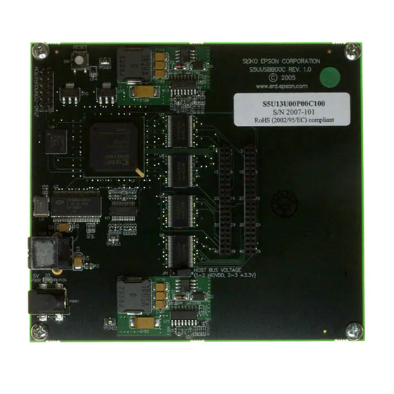
JP1 - Host Bus Voltage JP1 selects the voltage level of the host bus on connectors P1 and P2. When the jumper is at position 1-2, the voltage level is HIOVDD provided by the Epson LCD Controllers evaluation boards (recommended setting). -
Page 9: Status Indicators
Figure 4-1: Jumper JP1 Location 4.3 Status Indicators S5U13U00P00C100 has a green LED “5V PWR” to indicate when 5V power is present. The board outputs 2 signals on connector P1 to indicate if the board is working and if the board has completed enumeration on USB.These signals are 3.3 volt, regardless of the host... -
Page 10: Parts List
C26,C27,C62,C63,C64, C65,C66,C67,C68,C69, C70,C71,C72,C73,C74, C75,C76,C77,C78,C79, C80,C81,C117,C118, Yageo America C0402 C119,C120,C121,C122, 04022R102K9B20D C123,C124,C125,C126, C127,C128,C129,C130, C131,C132,C133,C134, C135,C136,C177,C189, C193,C201 C112,C113,C114,C115, Panasonic - ECG C116,C167,C168,C169, C0402 ECJ-0EB0J105M C170,C171 Kemet C181,C199 4.7uF 10V T C3528 T491B475K010AS Seiko Epson Corporation S5U13U00P00C100 USB 2.0 Adapter Board Rev. 1.1... - Page 11 CUI Stack Inc. PWR1 Power Jack 2BSM PJ-002A-SMT Sullins Electronics P1,P2 SOCKET_20x2 HDR2X20 PPWN102AFCN International Rectifier Q1,Q2 IRF8910 SOIC-8 IRF8910 R1,R2,R107,R117 2.7K R0603 R0603 R4,R5,R7,R8,R12,R13, R15,R16,R17,R18,R19, R20,R21,R22,R80,R81, R0402 R82,R83,R84,R85,R86, R87,R88,R96,R97,R98, Seiko Epson Corporation S5U13U00P00C100 USB 2.0 Adapter Board Rev. 1.1...
- Page 12 FG456 XC3S1500-4FG456C 4FG456C BG456 package; Insight/Memec Cypress CY7C68001- CY7C6800 CY7C68001-56PVXC 56PVC 1SSOP56 Cypress direct 24MHz CB3_OSC CB3LV-3C-24M0000-T Intergrated Circuit Systems SSOP_28_ ICS525-01 ICS525-01RI Insight, All-American, Nu Horizons U5,U6,U7,U8 74AVCB164245 SN74AVCB164245GR Seiko Epson Corporation S5U13U00P00C100 USB 2.0 Adapter Board Rev. 1.1...
- Page 13 Insight/Memec Micrel MIC37100- SOT-223 MIC37100-1.8BS 1.8BS Micrel direct STMicroelectronics U11,U13 L6910 SO-16 L6910TR Micrel MIC37100- SOT-223 MIC37100-2.5BS 2.5BS Micrel direct Texas Instruments TPS3801K33D SOT323-5 TPS3801K33DCKR IC 2.93V SUPPLY MON SOT-323-5 Seiko Epson Corporation S5U13U00P00C100 USB 2.0 Adapter Board Rev. 1.1...
-
Page 14: Schematics
Schematics 6 Schematics Figure 6-1: S1D13U00P00C100 Schematics (1 of 4) Seiko Epson Corporation S5U13U00P00C100 USB 2.0 Adapter Board Rev. 1.1... - Page 15 Schematics Figure 6-2: S1D13U00P00C100 Schematics (2 of 4) Seiko Epson Corporation S5U13U00P00C100 USB 2.0 Adapter Board Rev. 1.1...
- Page 16 Schematics Figure 6-3: S1D13U00P00C100 Schematics (3 of 4) Seiko Epson Corporation S5U13U00P00C100 USB 2.0 Adapter Board Rev. 1.1...
- Page 17 Schematics Figure 6-4: S1D13U00P00C100 Schematics (4 of 4) Seiko Epson Corporation S5U13U00P00C100 USB 2.0 Adapter Board Rev. 1.1...
-
Page 18: Pcb Layout
PCB Layout 7 PCB Layout Figure 7-1: S1D13U00P00C100 PCB Layout (Top) Seiko Epson Corporation S5U13U00P00C100 USB 2.0 Adapter Board Rev. 1.1... - Page 19 PCB Layout Figure 7-2: S1D13U00P00C100 PCB Layout (Bottom) Seiko Epson Corporation S5U13U00P00C100 USB 2.0 Adapter Board Rev. 1.1...
- Page 20 Revision 1.1 - Issued: March 26, 2018 • updated Sales and Technical Support Section • updated some formatting I00Z-G-018-01 Revision 1.0 - Issued: March 20, 2007 • Generate this document Seiko Epson Corporation S5U13U00P00C100 USB 2.0 Adapter Board Rev. 1.1...
-
Page 21: Sales And Technical Support
Sales and Technical Support 9 Sales and Technical Support For more information on Epson Display Controllers, visit the Epson Global website. https://global.epson.com/products_and_drivers/semicon/products/display_controllers/ For Sales and Technical Support, contact the Epson representative for your region. https://global.epson.com/products_and_drivers/semicon/information/support.html Seiko Epson Corporation S5U13U00P00C100 USB 2.0 Adapter Board...