
Related Manuals for Hanna Instruments HI8614

Summary of Contents for Hanna Instruments HI8614
- Page 1 Instruction Manual HI8614 • HI8614L HI8615 • HI8615L pH and ORP Transmitters w w w . h a n n a i n s t . c o m...
-
Page 2: Table Of Contents
If the repair is not covered by the warranty, you will be notified of the charges incurred. If the instrument is to be returned to Hanna Instruments, first obtain a Returned Goods Authorization number from the Technical Service department and then send it with shipping costs prepaid. -
Page 3: Preliminary Examination
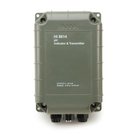
GENERAL DESCRIPTION HI8614 / HI8614L (pH) and HI8615 / HI8615L (ORP) are 2‑wire water‑resistant transmitters specially designed for long distance measurement of pH or ORP in industrial applications. HI8614 and HI8615 are models without LCD, and the HI8614L and HI8615L are models with LCD. - Page 4 100 V ensures true differential readings. The terminal board of the transmitter provides for connection of power supply, pH or ORP electrodes and temperature probe (for HI8614 family models only). The unit is enclosed in a protective casing conforming to IP65 standards.
-
Page 5: Specifications Of Hi8614 & Hi8614L
SPECIFICATIONS OF HI8614 & HI8614L Range 4 to 20 mA/ 0.00 to 14.00 pH Resolution 0.01 mA/ 0.01 pH Accuracy ±0.02 mA/ ±0.02 pH (@25 °C/77 °F) Offset: ±2.2 mA/ ±2 pH Calibration Slope: ±0.5 mA/ 86 to 116 % Temperature Fixed or automatic from 0 to 100 °C... -
Page 6: Specifications Of Hi8615 & Hi8615L
SPECIFICATIONS OF HI8615 & HI8615L Range 4 to 20 mA/ ±1000 mV Resolution 0.01 mA/ 1 mV Accuracy ±0.02 mA/ ±5 mV (@25 °C/77 °F) Offset: ±0.8 mA/ ±100 mV Calibration Slope: ±0.8 mA/ 90 to 110 % Input Impedance Output 4‑20 mA (isolated) Installation Category II... -
Page 7: Terminal Board Connections
TERMINAL BOARD CONNECTIONS Unscrew the 4 screws and remove the top cover. There are three cable glands on the transmitter cover. The large cable gland with the split in the rubber is for the electrode. Connect the positive supply to the strip terminal “+VE LOOP“ and the negative supply to the terminal “‑VE LOOP“... - Page 8 Electrode connection: connect the BNC of the cable to the BNC socket on the transmitter. For HI8614 family only: for automatic temperature compensation, connect the 2 terminals of the temperature probe (HI76608, optional) to “TEMP. PROBE“...
-
Page 9: Ph Calibration With Automatic Temperature Compensation
CALIBRATION WITH AUTOMATIC TEMPERATURE COMPENSATION (HI8614 family) INITIAL PREPARATION • Connect the pH electrode to the BNC socket. • Connect the temperature probe to the transmitter. Pour small quantities of pH7.01 and pH4.01 solution into two clean beakers. For accurate calibration use two beakers for each buffer solution, the first one for rinsing the electrode, the second one for calibration. - Page 10 PROCEDURE • Disconnect the +ve supply cable from “+VE LOOP“ terminal and connect a 20 mA f.s. ammeter between the +ve cable and “+VE LOOP“ terminal. • Remove the protective cap from the electrode, rinse it with some pH7.01 solution or immerse it in the pH7 rinse solution, then immerse the pH electrode and temperature probe into pH7.01 calibration buffer solution;...
- Page 11 • Adjust the slope trimmer until the ammeter reads 8.58 mA for HI8614 and HI8614L or the display shows “4.01“ at 25 °C. For other buffer temperatures, refer to page 12 for the appropriate mA / pH reading. If you are using pH10.01 buffer solu‑...
-
Page 12: (Hi8614 Family)
CALIBRATION WITH FIXED TEMPERATURE COMPENSATION (HI8614 family) • Take the temperature of the buffer solu‑ tions using a Checktemp or a thermometer with a resolution of at least 1 °C. • Connect the appropriate resistor to the “TEMP. PROBE” terminals (see page 8) depending on the temperature of the calibration solution. -
Page 13: Orp Calibration (H8615 Family)
ORP CALIBRATION (HI8615 family) INITIAL PREPARATION Disconnect the +ve supply cable from the “+VE LOOP” terminal and connect a 20 mA f.s. ammeter between the +ve cable and the “+VE LOOP” terminal. With HI8615L the instrument display can be used during calibration without the need to connect the ammeter. In this case the values are directly expressed in mV units. - Page 14 • If the reading lies outside this range, adjust the slope adjustment trimmer on the transmitter for a reading just within this range. The unit is now calibrated. A complete calibration of the transmitter module is advised periodically. This calibration procedure requires the HI8427 or the HI931001 pH and ORP simulator to simulate the ORP electrode.
- Page 15 • Connect the ORP electrode to the module and immerse the tip of the electrode into the beaker of HI7021 ORP solution and check that the ammeter reading lies between 13.8 and 14.1 mA for HI8615, or the instrument reading is between 240 ±20 mV at 25 °C (HI8615L only).
- Page 16 Please note: HI8615 or HI8615L ‑1000 mV 4 mA 0 mV 12 mA 1000 mV 20 mA 350 mV 14.8 mA 200 mV 13.6 mA 275 mV 14.2 mA 1 mV 12.008 mA Note: When the HI8615 and HI8615L are used in conjunction with the Hanna new HI8512 indicator or HI8720 controller, the calibration can also be performed on the indicator/controller.
-
Page 17: Electrode Conditioning & Maintenance
ELECTRODE CONDITIONING & MAINTENANCE PREPARATION PROCEDURE Remove the protective cap. DO NOT BE ALARMED IF ANY SALT DEPOSITS ARE PRESENT. This is normal with electrodes and they will disappear when rinsed with water. During transport tiny bubbles of air may have formed inside the glass bulb. - Page 18 For refillable electrodes If the fill solution (electrolyte) is more than 1 cm (½”) below the fill hole, add HI7082 3.5M KCl electrolyte solution for double junction or HI7071 3.5M KCl+AgCl electrolyte solution for single junction electrodes. For a faster response unscrew the fill hole screw during measurements.
- Page 19 • Dry Membrane/Junction: soak in HI70300 storage solution for at least one hour. • Drifting: soak the electrode tip in warm Hanna Instruments solution HI7082 for one hour and rinse the tip with distilled water. Refill with fresh HI7071 for single junction electrodes and HI7082 for double junction electrodes.
-
Page 20: Temperature Correlation For Ph Sensitive Glass
TEMPERATURE-RESISTANCE CORRELATION TEMPERATURE CORRELATION FOR HANNA pH SENSITIVE GLASS FOR pH SENSITIVE GLASS The resistance of glass electrodes partially depends on the temperature. The lower the temperature, the higher the resistance. It takes more time for the reading to stabilize if the resistance is higher. In addition, the response time will suffer to a greater degree at temperatures below 25 °C (77 °F). - Page 21 Alkaline Error High concentrations of sodium ions interfere with readings in alkaline solutions. The pH at which the interference starts to be significant depends upon the composition of the glass. This interference is called alkaline error and causes the pH to be underestimated. Hanna Instru‑ ments’...
-
Page 22: Installation Procedure And Examples
INSTALLATION PROCEDURE AND EXAMPLES The HI8614 family and HI8615 family transmitters may be wall mounted in any convenient location near the measurement point. To minimize thermal drift due to extreme temperature fluctuations during the measurement process, particularly if the measurement is conducted outdoors, it is best to protect the transmitter in an enclosed casing. - Page 23 Monitoring the pH/ORP with Panel Mounting pH (HI8510)/ORP (HI8512) Indicator Controlling the pH/ORP with an Industrial Regulator Monitoring and Controlling the pH/ORP with Panel Mounting Indicator/Regulator and Dosage Control of either Acid or Base...
- Page 24 Monitoring and Controlling the pH with (HI8711) Panel Mount- ing Indicator/Regulator with Independent Dosage Control for Acid and Base...
-
Page 25: Accessories
ACCESSORIES pH CALIBRATION SOLUTIONS HI7004M pH4.01 buffer solution, 230 mL HI7004L pH4.01 buffer solution, 500 mL HI7006M pH6.86 buffer solution, 230 mL HI7006L pH6.86 buffer solution, 500 mL HI7007M pH7.01 buffer solution, 230 mL HI7007L pH7.01 buffer solution, 500 mL HI7009M pH9.18 buffer solution, 230 mL pH9.18 buffer solution, 500 mL... - Page 26 pH ELECTRODES HI1090T Screwcap PG13.5 connector, double junction, glass body HI1110S Screw connector, single junction, glass body HI1130B/3 BNC connector, 3 m (9.9’) cable, single junction, glass body HI1110S HI1130B/3 HI1110T Screwcap PG13.5 connector, double junction, glass body HI1114S Screw connector, double junction plastic body HI1134B/3 BNC connector, 3 m (9.9’) cable, double junction plastic body...
- Page 27 HI1210T Screwcap PG13.5 connector, double junction, plastic body HI1910B BNC connector, 1 m (3.3’) cable, double junction, plastic body, built‑in amplifier HI1911B BNC connector, 1 m (3.3’) cable, double junction, plastic body, built‑in amplifier HI1912B BNC connector, 1 m (3.3’) cable, double junction, plastic body, built‑in amplifier HI1912B/5 BNC connector, 5 m (16.5’) cable, double junction,...
- Page 28 ORP ELECTRODES HI2930B/5 BNC connector, 5 m (16.5’) cable, Pt, plastic body, built‑in amplifier HI3110S Screw‑type connector, Pt, glass body HI3130B/3 BNC connector, 3 m (9.9’) cable, Pt, glass body HI3110T Screwcap PG13.5 connector, Pt, glass body Screw‑type connector, side‑arm, Pt, glass body HI3115S HI3135B/3 BNC connector, 3 m (9.9’) cable, side‑arm, Pt, glass...
- Page 29 HI3932B/5 BNC connector, 5 m (16.5’) cable, Pt, plastic body, built‑in amplifier HI4110S Screw‑type connector, Au, glass body HI4130B/3 BNC connector, 3 m (9.9’) cable, Au, glass body HI4932B/5 BNC connector, 5 m (16.5’) cable, Au, plastic body, built‑in amplifier...
- Page 30 EXTENSION CABLES FOR SCREW-TYPE ELECTRODES ONLY (SCREW TO BNC CONNECTOR) HI7855/1 Extension cable 1 m (3.3’) long HI7855/3 Extension cable 3 m (9.9’) long HI7855/5 Extension cable 5 m (16.5’) long HI7855/10 Extension cable 10 m (33’) long HI7855/15 Extension cable 15 m (49.5’) long OTHER ACCESSORIES Dosing pumps with flow rate from 1.5 to 20 lph BL PUMPS...
- Page 31 24 VAC or 60 VDC. To avoid damage or burns, do not perform any measurement in microwave ovens. Hanna Instruments reserves the right to modify the design, construction or appearance of its products without advance notice.
- Page 32 Hanna Instruments Inc. Highland Industrial Park 584 Park East Drive Woonsocket, RI 02895 USA Technical Support for Customers Tel. (800) 426 6287 Fax (401) 765 7575 E‑mail tech@hannainst.com www.hannainst.com MAN8614 09/17 Printed in ROMANIA...