Table of Contents
Advertisement
Quick Links
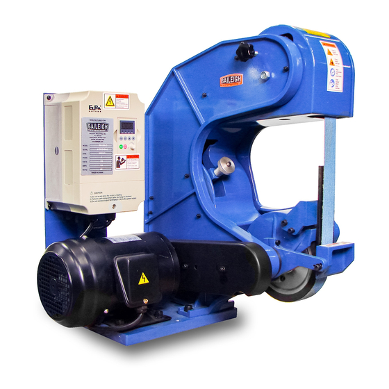
OPERATOR'S MANUAL
3 WHEEL BELT GRINDER
MODEL: BG-260-3-(110 OR 220)
Baileigh Industrial, Inc.
P.O. Box 531
Manitowoc, WI 54221-0531
Phone: 920.684.4990
Fax: 920.684.3944
sales@baileigh.com
REPRODUCTION OF THIS MANUAL IN ANY FORM WITHOUT WRITTEN APPROVAL OF BAILEIGH INDUSTRIAL, INC.
IS PROHIBITED. Baileigh Industrial, Inc. does not assume and hereby disclaims any liability for any damage or loss
caused by an omission or error in this Operator's Manual, resulting from accident, negligence, or other occurrence.
Rev. 12/2015
© 2015 Baileigh Industrial, Inc.
Advertisement
Table of Contents

Related Manuals for Baileigh BG-260-3-110


Summary of Contents for Baileigh BG-260-3-110
- Page 1 REPRODUCTION OF THIS MANUAL IN ANY FORM WITHOUT WRITTEN APPROVAL OF BAILEIGH INDUSTRIAL, INC. IS PROHIBITED. Baileigh Industrial, Inc. does not assume and hereby disclaims any liability for any damage or loss caused by an omission or error in this Operator’s Manual, resulting from accident, negligence, or other occurrence.
-
Page 2: Table Of Contents
Table of Contents THANK YOU & WARRANTY ..................1 INTRODUCTION ......................3 GENERAL NOTES ......................3 SAFETY INSTRUCTIONS ....................4 SAFETY PRECAUTIONS ....................6 TECHNICAL SPECIFICATIONS ................... 10 TECHNICAL SUPPORT ....................10 UNPACKING AND CHECKING CONTENTS ..............11 Cleaning ........................11 TRANSPORTING AND LIFTING .................. -
Page 3: Thank You & Warranty
THANK YOU & WARRANTY Thank you for your purchase of a machine from Baileigh Industrial. We hope that you find it productive and useful to you for a long time to come. Inspection & Acceptance. Buyer shall inspect all Goods within ten (10) days after receipt thereof. Buyer’s payment shall constitute final acceptance of the Goods and shall act as a waiver of the Buyer’s rights to inspect or... - Page 4 Baileigh Industrial makes every effort to ensure that our posted specifications, images, pricing and product availability are as correct and timely as possible. We apologize for any discrepancies that may occur. Baileigh Industrial reserves the right to make any and all changes deemed necessary in the course of business including but not limited to pricing, product specifications, quantities, and product availability.
-
Page 5: Introduction
After receiving your equipment remove the protective container. Do a complete visual inspection, and if damage is noted, photograph it for insurance claims and contact your carrier at once, requesting inspection. Also contact Baileigh Industrial and inform them of the unexpected occurrence. Temporarily suspend installation. -
Page 6: Safety Instructions
IMPORTANT PLEASE READ THIS OPERATORS MANUAL CAREFULLY It contains important safety information, instructions, and necessary operating procedures. The continual observance of these procedures will help increase your production and extend the life of the equipment. SAFETY INSTRUCTIONS LEARN TO RECOGNIZE SAFETY INFORMATION This is the safety alert symbol. - Page 7 SAVE THESE INSTRUCTIONS. Refer to them often and use them to instruct others. PROTECT EYES Wear safety glasses or suitable eye protection when working on or around machinery. PROTECT AGAINST NOISE Prolonged exposure to loud noise can cause impairment or loss of hearing.
-
Page 8: Safety Precautions
MOVING BELTS CAN CRUSH AND DISMEMBER DO NOT allow fingers to get pinched between belt and belt rollers. This may pull the operator’s hand into the machine causing serious personal injury. DO NOT operate without guards in place. HIGH VOLTAGE USE CAUTION IN HIGH VOLTAGE AREAS. - Page 9 4. Remove any adjusting tools. Before operating the machine, make sure any adjusting tools have been removed. 5. Keep work area clean. Cluttered areas invite injuries. 6. Overloading machine. By overloading the machine you may cause injury from flying parts. DO NOT exceed the specified machine capacities.
- Page 10 22. Be sure all equipment is properly installed and grounded according to national, state, and local codes. 23. Inspect power and control cables periodically. Replace if damaged or bare wires are exposed. Bare wiring can kill! DO NOT touch live electrical components or parts. 24.
- Page 11 35. Do not operate this machine if the gap between the moving abrasive belt, disc or wheel and the adjacent face of the work rest (or table) will permit passage of the work piece through the gap (nip point). WARNING: Certain alloys such as titanium may create conditions where grinding debris can accumulate in a tight gap creating a potential fire hazard.
-
Page 12: Technical Specifications
(other than die sets and blades). For specific application needs or future machine purchases contact the Sales Department at: sales@baileigh.com, Phone: 920.684.4990, or Fax: 920.684.3944. Note: The photos and illustrations used in this manual are representative only and may not depict the actual color, labeling or accessories and may be intended to illustrate technique only. -
Page 13: Unpacking And Checking Contents
UNPACKING AND CHECKING CONTENTS Your Baileigh machine is shipped complete. Separate all parts from the packing material and check each item carefully. Make certain all items are accounted for before discarding any packing material. WARNING: SUFFOCATION HAZARD! Immediately discard any plastic bags and packing materials to eliminate choking and suffocation hazards to children and animals. -
Page 14: Transporting And Lifting
TRANSPORTING AND LIFTING IMPORTANT: Lifting and carrying operations should be carried out by skilled workers, such as a truck operator, crane operator, etc. If a crane is used to lift the machine, attach the lifting chain carefully, making sure the machine is well balanced. Follow these guidelines when lifting with truck or trolley: ... -
Page 15: Installation
INSTALLATION IMPORTANT: Consider the following when looking for a suitable location to place the machine: Overall weight of the machine. Weight of material being processed. Sizes of material to be processed through the machine. Space needed for auxiliary stands, work tables, or other machinery. ... -
Page 16: Securing The Base
4” (102mm) thick. 6” (153mm) minimum is preferred. .50" (12.7mm) If you intend to mount the Baileigh machine on a workbench be aware of the following: Overall weight of the machine. Weight of material being processed. -
Page 17: Electrical
ELECTRICAL CAUTION: HAVE ELECTRICAL UTILITIES CONNECTED TO MACHINE BY A CERTIFIED ELECTRICIAN! Check if the available power supply is the same as listed on the machine nameplate. WARNING: Make sure the grounding wire (green) is properly connected to avoid electric shock. DO NOT switch the position of the green grounding wire if any electrical plug wires are switched during hookup. - Page 18 Improper connection of the equipment-grounding conductor can result in risk of electric shock. The conductor with insulation having an outer surface that is green with or without yellow stripes is the equipment-grounding conductor. If repair or replacement of the electric cord or plug is necessary, do not connect the equipment-grounding conductor to a live terminal.
-
Page 19: Operation
OPERATION CAUTION: Always wear proper eye protection with side shields, safety footwear, and leather gloves to protect from burrs and sharp edges. When handling large heavy materials, make sure they are properly supported. Initial Operation 1. Start the motor by pressing the ON button. The belt should rotate smoothly with the belt traveling downward (A) past the grinding area. -
Page 20: Grinding Operation
Grinding Operation This belt grinder is a three wheel path belt grinder that uses either a 1.5” x 60” (38 x 1524mm), or a 2” x 60” (51 x 1524mm) continuous loop abrasive belt. For maximum effectiveness, and operator safety use abrasive belts manufactured by well- respected abrasive manufacturers. -
Page 21: Material Selection
4. Press the ON button to start the motor. 5. Use the UP or DOWN arrow keys on the control pad to increase or decrease the belt speed as desired for the material and type of grinding being performed. 6. Using a firm grasp to hold the material, place the material on the work support and slide it in toward the belt allowing the material to remain on the work support. -
Page 22: Lubrication And Maintenance
LUBRICATION AND MAINTENANCE WARNING: Make sure the electrical disconnect is OFF before working on the machine. Maintenance should be performed on a regular basis by qualified personnel. Always follow proper safety precautions when working on or around any machinery. Note: Proper maintenance can increase the life expectancy of your machine. Daily Maintenance ... -
Page 23: Idler Wheel Alignment
Monthly Maintenance Apply light machine oil to the rear wheel support to rear wheel handle interface. Two drops of oil is sufficient. Check the v-belt tension. If you can hear the belt "slap" the belt guard when the drive motor starts, the v-belt requires tensioning. - Page 24 1. Disconnect and lockout power to the grinder! 2. Install the rear idler such that its inside-bearing surface is approximately 0.06 inches out from the wheel support. Secure the wheel with locking set screw. 3. Install the upper wheel such that its inner bearing surface is approximately 0.06 inches out from its bearing support.
-
Page 25: Parts Diagram
PARTS DIAGRAM... -
Page 26: Parts List
Parts List Item Description Qty. Variable-frequency Drive, VFD Work support for variable-frequency Drive, VFD Washer GB/T93 M4 Nut GB/T6172.1 M4 Motor Key GB/T1095 Nut GB/T172.2 M10 Cup point socket set screws GB/T77 M8X10 Star grip knob MY8314.22 M8X40 Button head cap screws GB/T70.2 M5X35 Compression Spring Bracket, pivot block Button head cap screws GB/T70.2 M5X12... - Page 27 Item Description Qty. Bearing GB/T276 6202-2Z Idler wheel Shaft Nut GB/T712.2 M12 Cross head screw GB/T819.1 M6X20 Flat washer GB/T95 6 Eye bolt Rear wheel support Washer GB/T93 6 Flat washer GB/T95 4 Semi-tubular rivet GB/T873 ∅4X15 Flat Head Thread Cutting Screw GB/T70.3 ∅5X12 Pawl Nipple, pipe Strip...
- Page 28 Item Description Qty. Washer for spring flange Contact wheel bushing Socket head cap screws GB/T70.1 M6X25 Work rest Spring pin GB/T897.1 ∅3X10 Socket head cap screws GB/T70.1 M6X30 Socket head cap screws GB/T70.1 M5X16 Bracket for platen Platen Socket head cap screws GB/T70.1 M6X20 Bolt GB/T5783 M10X40 Flat washer GB/T95 10 Base...
- Page 29 NOTES...
- Page 30 NOTES...
- Page 31 NOTES...
- Page 32 , WI 54220 UFEK RIVE ANITOWOC : 920. 684. 4990 F : 920. 684. 3944 HONE www.baileigh.com BAILEIGH INDUSTRIAL, INC. 1455 S. C , CA 91761 AMPUS VENUE NTARIO : 920. 684. 4990 F : 920. 684. 3944 HONE BAILEIGH INDUSTRIAL LTD. U...