
Related Manuals for Larius Pegaso


Summary of Contents for Larius Pegaso
- Page 1 Pegaso APPARATUS FOR SPRAYING INTERIOR FINISHING LAYERS ITALIANO Ediz. 02 - 07/2016...
- Page 2 Due to a constant product improvement programme, the factory reserves the right to modify technical details mentioned in this manual without prior notice.
-
Page 3: Table Of Contents
WE ADVISE THE USE OF THIS EQUIPMENT ONLY BY PROFESSIONAL OPERATORS. ONLY USE THIS MACHINE FOR USAGE SPECIFICALLY MENTIONED IN THIS MANUAL. Thank you for choosing a LARIUS S.R.L. product. As well as the product purchased, you will receive a range of support services enabling you to achieve the results desired, quickly and professionally. - Page 4 PEGASO WARNINGS The table below provides the meaning of the symbols used in this manual in relation to using, earthing, operating, maintaining, and repairing of this equipment. Read this operator’s manual carefully before using the equipment. An improper use of this machine can cause injuries to people or things.
-
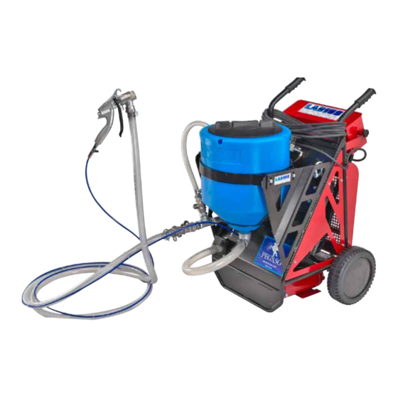
Page 5: Aworking Principle
WORKING PRINCIPLE On the end of the feed pipe there is a maximum pressure The PEGASO apparatus is an electric pump, used for spraying wall plaster or synthetic materials for covering valve, in order to eliminate choking or occlusions that can damage the pipe. - Page 6 PEGASO (A) 890 (B) 730 Ediz. 02 - 07/2016 www.larius.eu...
- Page 7 PEGASO Ediz. 02 - 07/2016 www.larius.eu...
- Page 8 PEGASO COMPONENTS DESCRIPTION POS. SEE TABLE COMPONENTS DESCRIPTION TABLE 01 - page 27 Frame Tank 50 L TABLE 02 - page 28 Group of control TABLE 03 - page 29 Pump TABLE 06 - page 32 Compressor TABLE 04 - page 30...
-
Page 9: Dtransport And Unpacking
• Before installing the equipment, ensure that the In case of damage, call immediately LARIUS and area to be used is large enough for such purposes, the Shipping Agent. All the notices about possible is properly lit and has a clean, smooth floor surface. - Page 10 PEGASO • NEVER SPRAY OVER FLAMMABLE PRODUCTS OR SOL- • BEFORE USING THE TOOL, ENSURE THERE ARE NOT VENTS IN CLOSED PLACES. DAMAGED PARTS AND THE MACHINE CAN WORK PRO- PERLY. • NEVER USE THE TOOLING IN PRESENCE OF POTENTIALLY EXPLOSIVE GAS.
-
Page 11: Fsetting-Up
PEGASO SETTING-UP CONNECTION OF THE FLExIBLE HOSE TO THE GUN • Connect the pressure flexible hose to the pump and the gun tightening the metal clamps. NEVER use sealants on fittings threads. The type of materiel you are spraying will determine the maximum lenght of hoseyou can use. If you are not achieving a satisfactory spray pattern or coverage, try using a shirter lenght of hose. -
Page 12: Gsetup
PEGASO SETUP • Connect one end of air hose to sprayer air outlet quick connect and to gun air inlet quick connect (G1). • Connect one end of material hose to material outlet and the other end to gun material inlet (G2). Firmly tighten the metal clamps. • Install spray nozzle (G3). See selection chart page 12. Pulling trigger when installing nozzles, eases assembly (G4). -
Page 13: Of The Tank
PEGASO POSITION AND INSTALLATION OF THE TANK • The 50 litre tank can be disassembled and easily cleaned. • Unscrew the bolts and insert/disengage the basket supporting the tank from the machine body, or lift the tank to remove it from its support. • Connect / disconnect the suction hose by opening the rapid coupling (H1) that permits the operations of filling / emptying the tank. -
Page 14: Icontrols
PEGASO CONTROLS Sprayer starter switch Display, pump pressure reading LED. - In the “0” position the machine is not powered - In the “1” position the machine is powered Power supply socket (220 V) for attaching supple- Emergency cut-out, making it possible to discon- mentary apparatus (such as a drill). -
Page 15: Startup
PEGASO SYSTEM START-UP ATTENTION: The spray gun cannot be used without compressed air supply. Check that the compressor is in operation, that all valves are open and adjust pressure by means of the corresponding pneumatic regulator (L5). START PUMP AND MATERIAL RECIRCULATION • Open the valve (L3). -
Page 16: Mwashing Of The New Equipment
PEGASO WASHING OF THE NEW EQUIPMENT • The equipment has already been adjusted at our factory with light mineral oil left inside the pumping group as protection. Therefore, wash with diluent before sucking the product. • Pour 4 litres of clean water into hopper (1). • Ensure the gun is without nozzle (2). WATER • Turn the sprayer on, adjust the air pressure (3). -
Page 17: Ostarting The Spraying Operations
PEGASO STARTING THE SPRAYING OPERATIONS • Use the tooling after performing all the SETTING UP operations above described. • Fill the tank with suitably prepared material. • Install the nozzle depending on the material you wish to use. See the nozzle selection table. If material gets in needle or gun air passages, Inspect material hose for kinks which flush with water immediately. - Page 18 PEGASO REGOLATIONS FLOW ADJUSTMENT • The flow of material must be adjusted at the sprayer using the fluid flow regulator handle and the value is shown on the display. ADJUSTING THE AIR • In order to decrease the air flow, turn the regulator anticlockwise (P1). • In order to increase the air flow, turn the regulator clockwise (P1). • Air passage opening and closing tap (P2). NOZZLE SELECTION • To select correct nozzle for your applications, con- sider size of aggregate in material and coarseness of spray pattern.
- Page 19 PEGASO CLEANING UP AFTER WORK • Reduce pressure to the minimum (turn counter- clockwise the pressure control knob) (1). • Empty remaining material into bucket until most of texture material is out of hopper (2). MATERIAL • Fill the tank with clean water (3), or connect a flexible hose which is connected to the water mains onto the hose adaptor (3A).
-
Page 20: Cleaning The Material Passage Hose
PEGASO CLEANING THE MATERIAL PASSAGE HOSE Suggested before storing the sprayer or when changing the material to be sprayed. Disconnect the material feed hose and the air feed hose from the gun; Disconnect the flexible material passage hose from the sprayer;... -
Page 21: Rprocedure Of Decompression
PEGASO PROCEDURE OF DECOMPRESSION • After having carried out all the operations described in the chapter concerning cleaning up after work, make sure that the system is not pressurised. • Squeeze the trigger and wait for all the material to have come out. If you suspect that there may be residual pressure in the hoses due to material clogging, loosen the metal hose clamps very slowly until you feel a decrease in pressure owing to the expulsion of the material. -
Page 22: Troutine Maintenance
PEGASO ROUTINE MAINTENANCE • To keep sprayer in good operating condition, always clean it thoroughly and prepare it properly for storage. The air hose fitting on sprayer can get hot! Allow sprayer to cool down 5 minutes before removing air hose. • Before removing the flexible material passage hose, release the pressure. MAINTENANCE PROGRAMME After ever use Daily Flexible air and material hoses • Drain the water •... -
Page 23: Uprocedure For Replacing The Hose
PEGASO PROCEDURE FOR REPLACING THE HOSE 3) Loosen the lower metal clamp (B) (photo 3). WARNING Before starting to replace the hose, accura- tely clean the machine. REMOVAL 1) Remove the side casing (photo 1). Photo 3 4) Remove the front plate (C), remove the two bolts (D) (photo 4). - Page 24 PEGASO 6) Start the machine, switch (F) on “1”; Start the pump, switch (G) on “ON”. Slightly increase the pressure of the pump by rotating the potentiometer (H) clockwise, the reading of the value is shown on the upper display (photo...
- Page 25 PEGASO WARNING If it is necessary to remove the pump from the machine, it is necessary to: • Remove the side casing (A). • Loosen the metal clamps (B) (C). • Remove the two attachment bolts (D). • Pull the pump, holding it by the handle fashioned inside the support.
-
Page 26: The Sensor Cleaning
PEGASO CLEANING AND REPLACING THE SENSOR CLEANING CLEANING circulate first in one direction and then the other, 1) If present, insert a flexible hose (A), connected to inverting the rotation of the pump (“PUMP ROTA- the water mains, or fill the tank with clean water;... -
Page 27: Wproblems And Solutions
PEGASO PROBLEMS AND SOLUTIONS Solution Problem Cause • The apparatus doesn’t • Lack of power; • Make sure the power line is con- start nected properly; • Strong drops in network voltage; • Check the extension cord; • On/Off switch disconnected; • Ensure the On/Off switch is on the “on” position and turn clockwise the pressure control knob; • Pressure sensor failure; • Verify and replace it, if necessary; •... - Page 28 PEGASO Problem Solution Cause • Material too thick; • Thin material; • Speed of application too slow • Nozzle too small; • Change nozzles to a larger size. See Operation Manual, Recommended Nozzle Selection Chart; • Flow control set too low;...
-
Page 29: Yspare Parts
PEGASO SPARE PARTS TABLE PAGE Groupe Group strutures RIF. 30566 Group reservoir RIF. 30560 Group of control RIF. 30569 Group compressor RIF. 30564 Group valves RIF. 30562 Group pumps RIF. 30561 Group of control air RIF. 30565 Group reservoir air RIF. 30563 Group gun Turbo Gun RIF. - Page 30 PEGASO TABLE 01 - GROUP STRUTURES RIF. 30566 13 15 Pos. Code Description Pos. Code Description 30511 Frame 21654 Knob 20303 Vheel 20272 Eyebolts 8371 Screw 19176 Bulkhead connector 95153 Wascher 30515 Cover 12454 Rubber buffer 54004 Screw 52017 54003...
- Page 31 PEGASO TABLE 02 - GROUP RESERVOIR RIF. 30560 Pos. Code Description Pos. Code Description 18249/1 Cover tank 20833 Elbow 18249 Tank 50L 30503 Rapid attachment 18246 Tank Support 20842 Rapid attachment 901568 Screw 30552 Clamp 34009 Wascher 30576 Suction hose 52017 Ediz.
- Page 32 PEGASO TABLE 03 - GROUP OF CONTROL RIF. 30569 GROUP OF CONTROL RIF. 30569 / 110 V Pos. Code Description Pos. Code Description 30514 Support 30546 Panel of closing 34009 Wascher 30523 Adhesive panel 8371 Screw 96028 Screw 30545 30547...
- Page 33 PEGASO TABLE 04 - GROUP COMPRESSOR RIF. 30564 GROUP COMPRESSOR RIF. 36564 / 110 V Pos. Code Description Pos. Code Description 30517 Support 6130 Screw 8371 Screw 33005 Wascher 95153 Wascher 5359 Fitting 53002/4 510049 Fitting 30542 Compressor 220 V*...
- Page 34 PEGASO TABLE 05 - GROUP VALVES RIF. 30562 GROUP VALVES RIF. 30562 / 110 V Pos. Code Description Pos. Code Description 30519 Plate of support 510423 Silencer 8371 Screw 11765 Screw 34009 Wascher 53002/4 30556 Fitting 30557 Fitting 3378 Prolong...
- Page 35 PEGASO TABLE 06 - GROUP PUMPS RIF. 30561 GROUP PUMPS 110 V RIF. 30561 / 110 Ediz. 02 - 07/2016 www.larius.eu...
- Page 36 PEGASO Pos. Code Description Pos. Code Description 30538 Peristaltic pump 220 V* 54004 Screw 30538/110 Peristaltic pump 110 V* 30524 Hose coupled 8371 Screw 30534 Fitting 34009 Wascher 8373 Fitting 30535 Hose 30532 Ball valve 30553 Clamp 30533 Rapid attachment...
- Page 37 PEGASO TABLE 07 - GROUP OF CONTROL AIR RIF. 30565 Pos. Code Description Pos. Code Description 3344 Regulator air 54004 Screw 510019 Fitting 54003 Wascher 3343 Prolong 510510 Plate of support 3341 Elbow 8042 8167 Gauge pressure 4004gg Ball valve Ediz.
- Page 38 PEGASO TABLE 08 - GROUP RESERVOIR AIR RIF. 30563 Pos. Code Description Pos. Code Description 30540 Reservoir air 34009 Wascher 30518 Support 91062 Screw 91557 Fitting 54003 Wascher 30559 Valve, security 8042 8371 Screw Ediz. 02 - 07/2016 www.larius.eu...
- Page 39 PEGASO TABLE 09 - GROUP GUN TURBO GUN RIF. 30568 7.5 7.6 7.3 7.4 Pos. Code Description Pos. Code Description 21051 Housing 21064 Air valve 21052 Trigger 21083 Air Spring 21053 Arrest for trigger 21065 Plug 21054 Locking nut Tip...
- Page 40 PEGASO TABLE 10 - GROUP GUN TEx GUN RIF. 30567 Pos. Code Description Pos. Code Description Complete gun without tip 30540 3563 Ball valve 30525 Attack for material pipe 9902 Check-valve 19165 Nipple 5313 Fitting Ediz. 02 - 07/2016 www.larius.eu...
-
Page 41: Accessories
PEGASO ACCESSORIES Pos. Code Description Tip Ø 3 21073 Tip Ø 4 21074 Tip Ø 6 21075 Tip Ø 8 21076 Tip Ø 10 21077 Tip Ø 12 21078 Pos. Code Description Filtering kit 30356 Filter 20101 Filter joint 30355 Pos. - Page 42 PEGASO Pos. Code Description Tank 100 lt 18243 Bag squeezing kit 18244 Pos. Code Description Mod. TIX 100 ER portable electric 217570ss mixer Ediz. 02 - 07/2016 www.larius.eu...
-
Page 43: Zair Diagram
PEGASO AIR DIAGRAM 1) Compressor 30542 2) Solenoid Valve 30537 3) Stator 30537/1 4) Connector 30537/2 5) Pressure switch 30536 6) Reservoir air 30540 7) Regulator air 3344 8) No return valve 50558 9) No return valve 9902 d=10 10) Security valve... - Page 44 PEGASO WIRING DIAGRAM Ediz. 02 - 07/2016 www.larius.eu...
- Page 45 PEGASO Ediz. 02 - 07/2016 www.larius.eu...
- Page 46 DIRECT LINE SERVICE TECHNIQUE Tel. (39) 0341.621256 - Fax (39) 0341.621234 MANUFACTURER: Paint spraying equipment 23801 CALOLZIOCORTE - LECCO - ITALY - Via Antonio Stoppani, 21 TEL. (+39) 0341/62.11.52 - Fax (+39) 0341/62.12.43 E-mail: larius@larius.com - Internet http://www.larius.eu...