
Related Manuals for Land Ametek RT8A


Summary of Contents for Land Ametek RT8A
- Page 1 RT8A Thermometer Installation Guide for Roadstone Applications Issue 3 25 November 2016 Publication Nº 806007 Language: English © Land Instruments International, 2010 - 2016...
- Page 2 Observe precautions for handling electrostatic discharge sensitive devices. Equipment Operation Use of this instrument in a manner not specified by Land Instruments International may be hazardous. Read and understand the user documentation supplied before installing and operating the equipment. The safety of any system incorporating this equipment is the responsibility of the assembler.
- Page 3 Design and Manufacturing Standards The Quality Management System of Land Instruments International is approved to BS EN ISO 9001 for the design, manufacture and on-site servicing of combustion, environmental monitoring and non-contact temperature measuring instrumentation.
- Page 4 RT8A Thermometer Installation Guide...
-
Page 5: Table Of Contents
Installation Guide RT8A Thermometer Contents About this Guide Preliminary Checks System Overview Positioning the Thermometer Drier Exit Chute Mixer Mixer Discharge Using a Sighting Tube Mounting the Thermometer Thermometer Cooling & Purging Air Supply Requirements Power Supply Requirements Electrical Connections 10.1 General Connections 11 Thermometer Installation Checking the System... - Page 6 RT8A Thermometer Installation Guide...
-
Page 7: About This Guide
Installation Guide RT8A Thermometer About this Guide This Installation Guide gives the basic information needed to install the RT8A thermometer correctly and get it working. More comprehensive information is given in the User Guide. Preliminary Checks Check the thermometer type and serial number against the details given on the delivery note. -
Page 8: System Overview
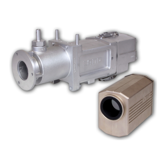
RT8A Thermometer Installation Guide System Overview The Roadstone thermometer is mounted inside a protection jacket which has a mounting flange to facilitate mounting into the mixer/drier (in some cases via a sighting tube). Cooling and purging air is supplied via the air purge inlet in the thermometer jacket and electrical power is connected to the thermometer via a demountable electrical connector. -
Page 9: Positioning The Thermometer
Installation Guide RT8A Thermometer Positioning the Thermometer 4.1 Drier Exit Chute Mount the thermometer on a sight tube and insert the tube vertically through the top plate of the exit chute, approximately midway along the chute. To ensure that the sight path is not obscured by airborne dust , the tip of the sight tube must not be more than 50mm (2 in) above the level of the stone (See Fig. -
Page 10: Mixer
RT8A Thermometer Installation Guide 4.2 Mixer Mount the thermometer either vertically on top of the mixer, or use a sight tube to mount it on the side of the mixer (See Fig. 4). Choose a point where the thermometer will not see the mixer paddles or, on a batch mixer, reflected flame via the discharge chute. -
Page 11: Mixer Discharge
Installation Guide RT8A Thermometer 4.3 Mixer Discharge Mount the thermometer below the mixer/storage bin discharge doors to view a solid curtain of falling material (See Fig. 5). Alternatively, position the thermometer such that it views into the skip or lorry and measures the temperature of the collected material. -
Page 12: Using A Sighting Tube
When fabricating the sighting tube be sure that the minimum internal diameter is no less than that shown in Fig. 6 for the length of sighting tube. Alternatively LAND offer a suitable sighting tube, i.e. Type FS6 150mm (6in) long. An adjustable sighting tube assembly facilitates efficient temperature measurement in the exit chute where airborne dust would otherwise adversely affect the thermometer readings. -
Page 13: Mounting The Thermometer
Installation Guide RT8A Thermometer Mounting the Thermometer When the sight tube has been fitted to the exit chute, use (3 off) M6 x 20 screws and nuts to attach the thermometer jacket to the mounting flange of the tube. The thermometer jacket also has a mounting boss on its base which can be used for mounting beneath the mixer/storage hopper. -
Page 14: Air Supply Requirements
The thermometer requires a power supply of 11 to 35V d.c. which is normally supplied by the LAND power supply unit or an indicator with loop power option. The power supply unit and the indicator require an a.c. supply of 110 or 240 volts (specified at time of ordering). -
Page 15: Electrical Connections
• Pre-wired 4m cable (Land Part No. 029.673) • 6-way plug (Land Part No. 206.551) • 6-way plug housed in protective jacket end cap (Land Part No. 091.562) Thermometer Pin Function Cable Colour End Cap Pin Nº V+, 4 to 20mA... -
Page 16: Thermometer Installation
RT8A Thermometer Installation Guide 11 Thermometer Installation Insert the thermometer into the thermometer jacket. Unscrew the small circular cap at the rear of the thermometer to reveal the emissivity and time response controls (See Fig. 10). Screw-on cap covering thermometer controls Rear face of RT8A thermometer Electrical Connector... - Page 17 Installation Guide RT8A Thermometer The thermometer, power supply and indicator are linked together on a current loop. Note: the indicator in the negative conductor as shown in Fig. 12. RT8A Thermometer 90/130 180/260 Power Supply Unit Indicator (Note: Indicator must be installed in the negative connector) Fig.
-
Page 18: Checking The System
RT8A Thermometer Installation Guide 12 Checking the System 12.1 Pre-operational checks Make the following checks before putting the system into operation: Check that there is no obscuration of the sight path between the thermometer and the material to be measured. Check that the thermometer lens is clean. -
Page 19: Cleaning The Lens
Installation Guide RT8A Thermometer 13 Cleaning the Lens The RT8A thermometer has a scratch-resistant coated lens. However, reasonable care is still needed to avoid lens damage. To clean the lens: Remove the jacket backcap and disconnect the electrical connector. Remove the thermometer from the jacket. Blow off any loose dust on the lens and wipe the lens with a soft cloth or brush. - Page 20 RT8A Thermometer Installation Guide Page 14...
- Page 21 We believe that our customers expect us to set the standard in terms of performance, quality, reliability and value for money. This 36 months warranty, as a part of an on-going program of continuous improvement, is just one way in which Land strive to maintain our position as the temperature measurement partner of choice.
- Page 22 It should be noted that costs associated with calibration checks which may be requested during the warranty period are not covered within the warranty. Land reserve the right to charge for service/calibration checks undertaken during the warranty period if the cause is deemed to fall outside the terms of the warranty.