Table of Contents
Advertisement
Advertisement
Table of Contents

Related Manuals for Honeywell Impact Series


Summary of Contents for Honeywell Impact Series
- Page 1 Impact Series Operating Instructions and Maintenance Manual...
-
Page 3: General Statement Of Limited Warranty
Honeywell Analytics shall not be liable for any incidental or consequential damages in connection with any deletions, errors or omissions in this Manual. - Page 4 Warranty Conditions The HA Limited Product Warranty only extends to the sale of new and unused products to the original buyer where purchased from a HA authorized distributor or service center. Not covered are: • consumable items such as dry-cell batteries, filters and fuses or routine replacement parts due to the normal wear and tear of the product;...
-
Page 5: Total Environmental Solutions
Impact. • The instrument must be serviced only by qualified personnel trained by Honeywell Analytics or by a Honeywell Analytics Appointed agent. Servicing must be carried out only in a non-hazardous area. • The Impact must not be used in an oxygen enriched atmosphere. - Page 6 The user of this manual should ensure that it is appropriate in all detail to the exact equipment to be installed and/or operated. If in doubt, the user should contact Honeywell Analytics for advice. If further details are required which do not appear in this manual, contact Honeywell Analytics or their agent. Note...
-
Page 7: Table Of Contents
2�1 Inserting the Cartridge ����������������������������������������������������������15 2�2 Charge For First Use ��������������������������������������������������������������16 2�3 Dry-cell Battery Insertion ������������������������������������������������������18 2�4 Sampling ���������������������������������������������������������������������������������19 2�5 How to turn Impact Series on and off ����������������������������������19 3� Instrument Start-up �������������������������������������������������������������������������20 3�1 Instrument Information ����������������������������������������������������������20 3�2 Selecting Location / Operator �����������������������������������������������20 3�3 Fresh Air Auto Zeroing Sensors �������������������������������������������21... - Page 8 4.5.2 Using Safelink ..............28 4�6 Pump (Impact Pro / Impact Pro IR Only) ������������������������������30 4.6.1 Removal of the Pump Adapter ........33 4�7 Menus ��������������������������������������������������������������������������������������33 4.7.1 Flammable Gas Selection ..........33 4.7.2 Operator .................35 4.7.3 Calibration ..............35 4.7.4 Instrument Details ............35 4.7.5 Safelink ................36 4.7.6 Language ...............36 4�8 Datalogging ����������������������������������������������������������������������������36 4.8.1 Installing the PC Software ..........36...
- Page 9 6�20 Ball float �������������������������������������������������������������������������������50 7� Routine Maintenance ����������������������������������������������������������������������51 7�1 Cleaning ����������������������������������������������������������������������������������51 7�2 Filters ��������������������������������������������������������������������������������������51 7�3 Battery Charging / Replacement �������������������������������������������51 7.3.1 Rechargeable Battery Pack ...........52 7.3.2 Dry Cell ................52 8� Routine Servicing ����������������������������������������������������������������������������53 8�1 Serviceable Cartridges ����������������������������������������������������������53 Special Notes for Cl Cartridges �������������������������������������������������54 Special Notes for SO Cartridges �����������������������������������������������58...
- Page 10 Impact / Impact Pro / Impact Pro IR Operating Instructions...
-
Page 11: Instrument Labels
Instrument Labels Neotronics Equipment Labels An explanation of the information on the equipment label is shown below. Manufacturers Name and Address Poole, Dorset Honeywell Analytics Ltd. BH17 ORZ, UK Impact Unit Part No. 2302B1000XXX CAUTION: Comms Connection only to other certified... -
Page 12: Lumidor Equipment Labels
Lumidor Equipment Labels An explanation of the information on the equipment label is shown below. Manufacturers Name and Address Sunrise, Florida Honeywell Analytics Inc. 33325, USA Impact Unit Part No. 2302B2000XXX CAUTION: Comms Connection only to other certified Impact detectors in hazardous area... -
Page 13: 1� Introduction
1� Introduction The Impact Series is a compact, portable gas monitor designed to be carried or worn without hindering the user. Its purpose is to monitor the atmosphere continuously for hazardous levels of up to four gases. Audible and visual alarms alert the user to danger when hazardous conditions are detected. -
Page 14: 1�1 Intended Use
1�1 Intended Use The Impact Series has been designed to alert the user to potentially hazardous atmospheres while carrying out his/her normal duties. Therefore, the instrument must be kept switched on and worn as close to the breathing area as possible, and... -
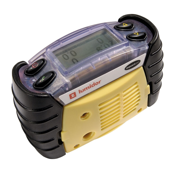
Page 15: 1�2 Product Overview
1�2 Product Overview 1. Buttons 2. Pump Aperture 3. Cartridge and Filter Cover Grille 4. Audible Aperture 5. Cover Grille Screws 6. Equipment and Certification Label 7. Battery Compartments 8. Tool 9. Data Connector On the top of the unit are four buttons (1). Their functions are summarized below: �... -
Page 16: 2� Getting Started
2� Getting Started 2�1 Inserting the Cartridge If the instrument is switched on then switch it off by pressing and holding button. Note: if a cartridge is already fitted, check that the instrument clock is correct. Undo the two cover grille screws (5). If a cartridge is already fitted then remove it by undoing the central screw. -
Page 17: 2�2 Charge For First Use
2�2 Charge For First Use Either a rechargeable battery pack or a dry-cell battery source can power the Impact. For the rechargeable battery it must be charged before first use, to replace any battery capacity used during transit and storage. Ensure the Base Station is connected to a suitable power source. - Page 18 Disengaged Engaged To remove the Impact press down on the rear locking catch. All 4 alarm lights will flash indicating the Impact has started charging. While charging the instrument, the instrument will flash 2 red LEDs approximately every 4 seconds. When charging is complete it will light the green LEDs constantly.
-
Page 19: 2�3 Dry-Cell Battery Insertion
2�3 Dry-cell Battery Insertion 1. Buttons 2. Pump Aperture 3. Cartridge and Filter Cover Grille 4. Audible Aperture 5. Cover Grille Screws 6. Equipment and Certification Label 7. Battery Compartments 8. Tool 9. Data Connector Undo the two battery compartments (7) using the supplied Allen wrench (9) provided, on the bottom of each instrument. -
Page 20: 2�4 Sampling
When using the built-in pump or hand aspirator ensure that the sampling tube is not inserted into a fluid. 2�5 How to turn Impact Series on and off The Impact has been designed for ease of use, and especially for one-handed operation - only a single button is needed to turn it on and off. -
Page 21: 3� Instrument Start
After turning the instrument on it will display the information in the following auto sequence (depending on model): The first display identifies the model. While this is shown the alarms are tested and, if a vibrating alarm is fitted this is also activated. Honeywell Honeywell Impact Impact Pro... -
Page 22: 3�3 Fresh Air Auto Zeroing Sensors
(bump test). If using the Enforcer for calibration checking or bump testing, refer to Section 4.9.4. For more information on test gas, contact your local Honeywell Analytics representative. Impact / Impact Pro / Impact Pro IR Operating Instructions... -
Page 23: 4� Operation
4� Operation Note Wherever the manual says ‘select’, the procedure is to use the s and t buttons to cycle through the list, and then press 3 to select the required option. 4�1 Monitoring Condition 4�1�1 Display Screens With no alarm conditions the display will typically show: %V/V %LEL 20.9... -
Page 24: Other Displayed Symbols
Status Screen This screen shows the current time, date and battery status. 18:33:00 It is possible to change the instrument date and time 22/Jan/2007 setting as follows: Press the 3 key while this screen is displayed and the clock setting function will be activated, with the hour field highlighted. -
Page 25: Confidence Signal
4�1�3 Confidence Signal To ensure correct operation the instrument monitors itself and will confirm correct operation by giving an audible and green visual confidence signal once every 30 seconds. The confidence signal is given when the instrument is able to detect gas (for example the confidence signal will not be given during pump or sensor calibration phases, or if the sensors are in warm-up). -
Page 26: 4�3 Alarm Condition
4�3 Alarm Condition There are two modes of alarm: latching and non-latching. However, the display will give the same alarm indication: An alarm symbol will appear in the relevant section of %V/V %LEL the display. The alarm symbol contains a number, indicating the increasing severity of the alarm, with increasing frequency of the audible and visual alarms. -
Page 27: Warning
Code - 0 warning the user and giving a contact number. This will Please contact Honeywell Analytics remain until the instrument is turned off by pressing the H A Service Number button for at least 3 seconds. -
Page 28: 4�5 Safelink
4�5 Safelink 4�5�1 What is Safelink? Safelink is a confined space entry communication system between instruments, fitted with the Safelink feature. It allows one instrument (the ‘attendant’) to display the gas readings measured by the other connected instrument (the ‘entrant’), up to a maximum cable length of 100m. -
Page 29: Using Safelink
4�5�2 Using Safelink Connect the Safelink cable between two instruments. Turn on each instrument and from the user menu on each instrument select the Safelink mode. On one instrument select Attendant. When selecting the Safelink Mode Attendant on one instrument the instrument will display Attendant ‘locating’... - Page 30 By pressing the 3 button the entrant has access to a Select Message menu, to select a message to send to the attendant. These are configurable using the PC software, and could Message 1 Message 2 be used to indicate work progress, e.g. ‘Valve Now Message 3 Message 4 Closed’.
-
Page 31: 4�6 Pump (Impact Pro / Impact Pro Ir Only)
4�6 Pump (Impact Pro / Impact Pro IR Only) The pump allows gas to be drawn through tubing across the sensors. Fitting the Pump Adapter will automatically switch the pump on. If the pump is operating correctly the pump symbol will rotate. Please refer to Section 4.1.2 Other Displayed Symbols on the operation of the instrument under blocked flow conditions. - Page 32 Remove the blockage from the sample tube and press the 3 button. The internal sample pump feature is now ready for use. To stop the sample pump, remove the Pump Adapter as described in Section 4.6.1 Removal of the Pump Adapter. If the Pump Test fails then the pump calibration procedure will start.
- Page 33 ‘Please block pump screen’ is displayed. The Pump Assembly is faulty. Request a new Pump Assembly or contact Honeywell Analytics for assistance. PUMP FAULT and The Pump Calibration has failed. Remove the Pump Adapter and...
-
Page 34: Removal Of The Pump Adapter
4�6�1 Removal of the Pump Adapter To ease the removal of the Pump Adapter, follow the steps below. Support the end of the Pump Adapter close to the inlet port using the thumb of one hand. Press on the top of the clip using the thumb of the other hand until a click is heard. - Page 35 4.7.1.1 Flammable Cross-Sensitivity Table EN50054 EN61779 Flammable Gas Relative Sensitivity Relative Sensitivity (% of Methane Reading) (% of Methane Reading) Hydrogen Methane Ethylene Methanol Ethane Ethanol Propane Butane Pentane Octane Note The above data are applicable only to instruments that have catalytic sensors configured to display the Flammable gas in % LEL.
-
Page 36: Calibration
Language Fitted Latched English The following additional information is also displayed: Cartridge SN Cartridge Type 0001138 Standard Honeywell Analytics Date of Manufacture Install By Sunrise, FL 25/Jun/2001 26/Dec/2001 800 538 0363 Boot ROM Version Date of Activation Impact Boot 1.4+... -
Page 37: 4�8 Datalogging
PC software. 4�8�1 Installing the PC Software Insert the CD into your CD-ROM drive. From the Impact Series ICU Utility Page, click “Install Impact Configuration Utility”. If the CD does not autorun, click Start, then Run. In the Run dialog box, type d:\Documents\ICU\setup.exe, where d is the letter assigned to your... -
Page 38: Event Datalogging
4�8�2 Event Datalogging All instruments are supplied complete with event datalogging. This records the time and date whenever an event occurs. When the datalogging memory is full then the earliest data is overwritten. In event mode the datalogging memory can store at least 500 events. -
Page 39: 4�9 Calibration
4�9 Calibration The accuracy of the Impact instrument should be checked with known concentration calibration gas before each day’s use. If any sensor fails recalibrate the Impact before using, or replace the cartridge. It is recommended that the instrument be calibrated at least every 6 months. - Page 40 S Response CO Response Applied Gas (ppm) (ppm) Acetone (1000 ppm) Acetylene (40 ppm) Ammonia (50 ppm) Carbon Monoxide (50 ppm) Carbon Dioxide (5000 ppm) Chlorine (0.5 ppm) Ethanol (2000 ppm) Ethylene (100 ppm) Hydrogen (100 ppm) Hydrogen Sulfide (10 ppm) Iso-Propanol (200 ppm) Nitric Oxide (25 ppm) Nitrogen Dioxide (3 ppm)
-
Page 41: Flow Calibration - Instrument
4�9�2 Flow Calibration – Instrument Note: For Cl and NH sensors, see Section 8 Special Considerations for Cl and Special Considerations for NH for more information, The following equipment is required: • cylinder of calibration gas (either certified individual gas per sensor or a certified multi-gas mixture) •... - Page 42 � If the zero was unsuccessful repeat the zero ensuring that the instrument is in fresh air. If a second failure occurs contact local service center or Honeywell Analytics for assistance. After a successful zero a span should be performed.
- Page 43 If a second failure occurs contact local service center or Honeywell Analytics for assistance. If the calibration is successful, the unit will automatically update the next calibration required by date by the predefined calibration interval value (default 180 days).
-
Page 44: Flow Calibration - Pc
Select Gas Select Gas ----- Methane Propane Butane Pentane Catalytic Sensor IR Sensor Honeywell Analytics recommends the following calibration gas concentrations: Gas Type Concentration Gas Type Concentration Catalytic Flammable (%LEL): 50% LEL Methane Carbon Dioxide: 2% v/v Flammable (%v/v): 2.5% v/v Methane... -
Page 45: Enforcer Calibration
4.9.4.1 Enforcer On-Screen Instructions If it is not already fitted, screw the Honeywell Analytics cylinder in tightly (multi-gas mix for Enforcer), check that the pressure gauge shows gas pressure is present, and pull back the instrument drawer. -
Page 46: 5� Fault Finding And Procedures
The instrument will recognize the Enforcer and display an instruction to press the 4 button to continue. Enforcer Calibration Press to continue � When 3 is pressed, the user should hear the distinctive ‘click’ of the Enforcer gas delivery solenoid valve. After about 90 seconds the instrument will display either a pass or fail. -
Page 47: 6� Accessories
6� Accessories WARNING Do not attempt to charge the battery pack in the hazardous area. The following accessories are available for use with Impact Series. 6�1 Base Station (Part Number: P2302B0800) This unit provides a smart charging facility for instruments powered by rechargeable NiMH batteries. -
Page 48: 6�4 Offline Trickle Charger
6�4 Offline Trickle Charger (Part Number: 2302B141x) Permits off-instrument charging of 2 or 4 instrument battery packs in 14 hours. It enables 24 hour availability of rechargeable instruments with purchase of additional battery packs. Battery packs must be charged in pairs. A power supply is included in the trickle charger kit. -
Page 49: 6�6 Enforcer
6�6 Enforcer (Part Number: 2302B0831 UL Version including gas cylinder) (Part Number: 2302B1336 ATEX Version including gas cylinder) (Part Number: 2302B0650 Enforcer only) This test and calibration accessory is only for use with instruments fitted with any combination of oxygen, flammable (catalytic or IR LEL sensor), carbon monoxide and hydrogen sulfide sensors. -
Page 50: 6�11 Body Harness Kit
6�11 Body Harness Kit (Part Number: P2302B0822) Simply clips onto the rear of the instrument. Allows the instrument to be worn on the chest within the breathing zone. Comes with a waist strap and neck strap. 6�12 Pump Adapter Kit (Part Number: 2302B0814) When attached to the front of an instrument fitted with a pump, the pump will be automatically activated. -
Page 51: 6�16 Safelink Cable Assembly
6�16 Safelink Cable Assembly This is available in 3 different lengths and allows Safelink enabled instruments to be connected together for communications, see Section 4.5 Safelink. 10m (33’) + 2 x Cable Restraints 2302B0735 50m (150’) + 2 x Cable Restraints 2302B0737 100m (300’) + 2 x Cable Restraints 2302B0746 2302B0746 is supplied with a cable reel and an adapter. -
Page 52: 7� Routine Maintenance
7� Routine Maintenance The Impact Series is designed to operate almost maintenance free under most conditions, except for the need for regular calibration. However, it is recommended that on a regular basis the instrument is cleaned and the filters changed. -
Page 53: Rechargeable Battery Pack
The rechargeable battery packs are sealed units. Do not attempt to remove the cells from the packs as this will invalidate the safety certification. Battery packs can be recycled by returning to the nearest Honeywell Analytics Appointed Distributor. Remove the battery packs if the instrument will not be used for some time. -
Page 54: 8� Routine Servicing
8� Routine Servicing Apart from the maintenance described in Section 7 Routine Maintenance the servicing requirements are limited to: • Calibration • Changing of the cartridge when required or indicated by the instrument • Replacing sensors in serviceable cartridges (i.e. non-OFCH combinations where supported by the instrument) 8�1 Serviceable Cartridges Instruments that support serviceable cartridges can have the individual sensors... -
Page 55: Special Notes For Cl 2 Cartridges
Special Notes for Cl Cartridges It is important that you read all of the notes below before installation or use of your new cartridge. Installation of your Cl Cartridge Note Cartridge Installation or Replacement must never be carried out in a hazardous area. - Page 56 Using your Cl Cartridge Please ensure that the following points are noted when the cartridge is in service. Always use PTFE tubing (maximum length of 500mm) and a flow rate of 500ml/min when calibrating the Cl channel. Apply all gases to the port marked OUTLET (not INLET) on the Flow Housing.
- Page 57 Special Notes for NH Cartridges It is important that you read all of the notes below before installation or use of your new cartridge. Installation of your NH Cartridge To install the cartridge, follow the instructions below. Note Cartridge Installation or Replacement must never be carried out in a hazardous area.
- Page 58 The sensors fitted to Impact Pro may give responses to gases other then the target gas. The table below gives typical sensor responses to various gases and should be used as a guide only. Note: Always use the target gas to perform sensor calibrations. Your attention is drawn to the cross-sensitivity of the NH sensor in the presence of H...
- Page 59 Special Notes for SO Cartridges It is important that you read all of the notes below before installation or use of your new cartridge. Installation of your SO Cartridge Note Cartridge Installation or Replacement must never be carried out in a hazardous area.
- Page 60 The sensors fitted to Impact Pro may give responses to gases other then the target gas. The table below gives typical sensor responses to various gases and should be used as a guide only. Note: Always use the target gas to perform sensor calibrations. Effect Effect Effect...
-
Page 61: Special Notes For Electrochemical Co Cartridges
Special Notes for Electrochemical CO Cartridges It is important that you read all of the notes below before installation or use of your new cartridge. Installation of your electrochemical CO Cartridge The cartridge is supplied on a Bias PCB to ensure that the sensor is ready to use when installed. - Page 62 If using Rechargeable Ni-MH Battery Packs, charging should always be carried out with the batteries removed from the instrument. This can be achieved by using the Honeywell Analytics Off-Line Charger. Part numbers of the chargers are given in Section 6 Accessories.
-
Page 63: Using Alkaline Dry Cells
from the Off-Line Charger. Remove the instrument from the Base Station and insert the Battery Packs. Tighten the retaining screw using the special tool. The instrument is now ready for use. Note: The instrument does not have to be switched on during this procedure, however if it is switched on a Warning 105 (see Appendix A) will be shown. -
Page 64: Special Notes For No
Special Notes for NO Cartridges It is important that you read all of the notes below before installation or use of your new cartridge. Installation of your NO Cartridge Note Cartridge Installation or Replacement must never be carried out in a hazardous area. - Page 65 for a period of 15 minutes between NH S or Cl and NO calibrations to avoid interaction between these gases. The sensors fitted to Impact Pro may give responses to gases other then the target gas. The table below gives typical sensor responses to various gases and should be used as a guide only.
-
Page 66: Special Notes For Ir Sensors
WARNING All IR sensor cartridges require a modified Impact Pro IR cartridge bay, which is designated as modification state 15. If not present, this modification must be performed by your authorized Honeywell Analytics Service Center. Failure to do this may lead to physical damage when attempting to insert the new IR sensor cartridge and will not be covered by warranty. - Page 67 linearly to methane (CH ). Response to other hydrocarbons is non-linear and the Impact Pro IR will not display corrected values for other hydrocarbon gases. The Impact Pro IR will generally (but not always) give a higher reading for heavy hydrocarbons than for methane.
- Page 68 Methane %V/V and CO IR sensors can be calibrated only by using a separate cylinder and regulator. Contact Honeywell Analytics for full details of calibration gases and accessories. When performing a calibration (other than with an Enforcer) the gas flow should be started 30 seconds before starting the span calibration sequence.
-
Page 69: 9� Spare Parts
9� Spare Parts The following spare parts are available from Honeywell Analytics authorized Service Centers, in addition to the accessories listed in Section 6 - Accessories. Part Number Description Lumidor Spares and Consumables 2302B0845 In-Line Filter - Package of 10... - Page 70 Hydrogen Sulfide 2119B1001 Carbon Monoxide 2119B1002 Chlorine 2302B0769 Toxic Blank Cell - Package of 10 2302B1081 Flammable %LEL (IR) 2302B1082 Flammable %Vol (IR) 2302B1083 Carbon Dioxide %Vol (IR) Note In order to meet Certification Requirements, fit only Honeywell Analytics component approved flammable sensor. Impact / Impact Pro / Impact Pro IR Operating Instructions...
-
Page 71: 10� Glossary
10� Glossary BASEEFA British Approvals Service for Electrical Equipment in Flammable Atmospheres – UK Safety Certification Bump Test Check of basic functionality by exposure to test gas, resulting in a gas indication or alarm condition. Catalytic Sensor For detection of combustible gases. These are made of an electrically heated platinum wire coil, covered first with a ceramic base such as alumina and then with a final outer coating of palladium... - Page 72 Hazardous Areas Areas where there is the possibility of the presence of an explosive mixture of flammable gas or vapor and air are known as ‘Hazardous’ and other areas as ‘safe’ or ‘non-hazardous’. Any electrical equipment used in hazardous areas must be tested and approved to ensure that, in use even under fault conditions, it can not cause an explosion.
- Page 73 Peak Maximum, or minimum, measurement since switch on. Pellistor Registered trade name for a commercial device – A very small sensing element used in catalytic sensors and sometimes also called a ‘bead’ or a ‘siegistor’. Poison resistant Capability of a catalytic sensor to reduce the effect of inhibiting substances or contaminants, such as silicones.
-
Page 74: Appendix
Appendix A A�1 Fault/Warning Codes Number Message Action or Reason Clear log to reset. Log memory error. Clear the event log Clear log to reset. Log memory error. Clear the gas log See manual Memory fault Insert valid cartridge Insert a valid cartridge. If one is fitted, remove and refit. - Page 75 Number Message Action or Reason Switch on/off to reset Caused by an unexpected switch off, e.g. poor or intermittent battery contacts. Switch off instrument and switch on again. Please recharge or replace batteries Insufficient battery voltage to operate the Enforcer. Recharge battery or replace the battery pack.
- Page 76 Number Message Action or Reason Switch on/off to reset • Faulty sensor or poor cartridge contact • Remove and refit cartridge • Replace suspect sensor (serviceable cartridge) • Replace cartridge. Switch on/off to reset • Software Algorithm Error • Switch instrument off and back on to clear the fault.
-
Page 77: Appendix
Appendix B B�1 Warranty Honeywell Analytics operates a standard warranty statement (See Page 3). B�2 Certification Approvals B�2�1 Impact/Impact Pro (non-IR) Approvals Europe CENELEC (ATEX) BAS 01 ATEX 1216 Ex 112G EEX ia d IIC T4 (-20°C to +55°C) North America UL Ex ia Class 1 Div 1 Group ABCD T4 T (-4°F to +131°F). -
Page 78: Exam (Dmt) Test Report
Special Co nditions for Safe Use • The portable gas detector Impact Series by Honeywell Analytics Ltd. is based on the information and test results contained in the test reports PFG-No. 41300502P and PFG No. 41300502P NI to 41300502P NIV,... -
Page 79: Safelink Connection Drawing
• Additional marking instructions, according to EU Directive 94/9/EG in particular, are unaffected. The manufacturer confirms with this type label that the instrument supplied contains the documented features and technical characteristics as described in this report. Each instrument without such a label does not conform to this report. •... -
Page 80: B�3 Technical Specifications
B�3 Technical Specifications B�3�1 Instrument Specification Weight 520g (18oz) including rechargeable battery packs and pump Dimensions 49mm x 84mm x 136mm (1.9” x 3.3” x 5.3”) Electrochemical/ Response Warm-up Impact Range Repeatability Impact Catalytic Sensors Time (T90) Time (s) Flammable 0 to 100% LEL ±3% LEL See B.3.3... -
Page 81: Charger Specifications
B�3�2 Charger Specifications 2302D0816 230VAC 50Hz Euro plug format, 12Vdc 500mA regulated output 2302D0818 230VAC 50Hz UK plug format, 12Vdc 500mA regulated output 2302D0819 120VAC 60Hz USA plug format, 12Vdc 500mA regulated output 2302D0820 240VAC 50Hz Australian plug format, 12Vdc 500mA regulated output 2302D0815 12V/24VDC vehicle charger lead Storage Temperature (all versions): –20°C to +50°C Operating Temperature (all versions): 0°C to +35°C... -
Page 82: Specific Recovery Time Data (Falling Gas Levels)
B�3�4 Specific Recovery Time Data (Falling Gas Levels) The following values are typical recovery times, given in seconds during various gas-sampling modes of the instrument. Sampling Mode (see key) - typical T10 recovery time (seconds) Sampling Mode (see key) - typical T20 recovery time (seconds) Sampling Mode (see key) - typical T0 recovery time (seconds) 1220 Key:... - Page 84 Data may change, as well as legislation, and you are strongly advised to obtain copies of the most recently issued regulations, standards and guidelines. This publication is not intended to form the basis of a contract. 2302M5030 Rev 11 March 2008 © 2008 Honeywell Analytics...