Table of Contents
Advertisement
Quick Links
T E C H N O L O G I E S
C1795
Manual No. 043D6C
Issue Av2
GDS404+
SERIES
OPERATING HANDBOOK
This document is not contractual and the equipment specification may be modified at any time without prior notice.
E:
sales@gds-technologies.co.uk
T:
+44 (0)113 286 0166
www.gds-technologies.co.uk
GDS TECHNOLOGIES LTD
|
FUSION POINT
|
ASH LANE
|
GARFORTH
|
LEEDS
|
LS25 2GA
|
UK
Advertisement
Table of Contents

Related Manuals for GDS 404+ Series


Summary of Contents for GDS 404+ Series
- Page 1 Issue Av2 GDS404+ SERIES OPERATING HANDBOOK This document is not contractual and the equipment specification may be modified at any time without prior notice. sales@gds-technologies.co.uk +44 (0)113 286 0166 www.gds-technologies.co.uk GDS TECHNOLOGIES LTD FUSION POINT ASH LANE GARFORTH LEEDS LS25 2GA...
-
Page 2: Table Of Contents
Contents Description ..................................3 Technical Specification ................................. 4 Installation...................................5 Commissioning ..................................6 Service – routine attention ..............................8 Table of lower explosive limits ...............................9 Table of occupational exposure limits – P .P .M..........................9 ILLUSTRATIONS Front View – Controls ..............................9 Display Boards ................................10 Mother Board Detail and Field Terminals ........................11 Alarm Board –... -
Page 3: Description
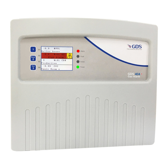
Description The GDS 404+ is a multi channel combustible and toxic gas monitor, which can accommodate up to 4 sensor channels housed in wall mounting enclosure. Sensors may be added or removed as required, but should be carried out with the power to the unit switched off. Each sensor continuously monitors for gas, the display will show the gas type being monitored, the current gas reading and the location of the sensors. -
Page 4: Technical Specification
Technical Specification NUMBER OF CHANNELS ONE, TWO, THREE OR FOUR CHANNELS OUTPUTS Common Relays – user selectable • High Alarm RL2 – D.P .C.O normally energised or de–energised– default set ND • Latched or Unlatched – default set latched • Low Alarm RL1 – D.P .C.O. normally energised or de–energised– default set ND •... -
Page 5: Installation
Installation The GDS 404+ Series control instrumentation is designed for installation in a safe area only. Siting of the instrument should be chosen with regard to the following points: (a) Cable within the enclosure should be cut back to the minimum length and having been terminated should be kept away from electronic components and the ribbon cable. -
Page 6: Commissioning
POISONING OF CATALYTIC SENSORS Catalytic elements used in flammable gas sensors are liable to be rendered inactive due to ‘poisoning’ by certain groups of compounds. In general contact with any gaseous compound capable of producing an involatile residue upon heating is to be avoided. - Page 7 ‘device manager’ ports for example. The terminal program should be set up using the same method and settings as the GDS combi panel (baud rate 2400). The terminal window will appear as below. Follow the onscreen instructions: Press the character on the left of the list of commands to change that specific setting.
-
Page 8: Service - Routine Attention
SENSOR SUPPLY ADJUSTMENT (CATALYTIC SENSOR) Factory set – no further adjustment required unless a change of sensor type is being made. For ease of setting, measurements are taken across a 1ohm resistor (located on each sensor board) which is connected in series with the supply to the detector head. Current required by each type of sensor is (VQ21–300mA/ VQ23 DCP–335mA) therefore, measuring mV across the 1 ohm resistor at test point TP1 or TP2 (on the mother board) and sv test point on each sensor board, will provide a mV reading proportional to mA’s supplied, adjustment may be carried out using the sensor volts adjustment potentiometer. -
Page 9: Table Of Lower Explosive Limits
ACTION TO BE TAKEN IF THE APPARATUS ALARM SOUNDS: Extinguish all naked flames, including all smoking materials. Turn off all gas appliances. C Do not switch on or off any electrical lights or appliances. D Turn off the gas supply at the gas emergency control and/or (with L.P .G supply) the storage tank. Open doors and windows to increase ventilation If the alarm continues to operate, even after an alarm re–setting action where appropriate, and the cause of the leak is not apparent and/or cannot be corrected, vacate the premises and immediately notify the gas supplier and/or the... -
Page 10: Display Boards
Fig. 2 Spare Jumpers Option A Option B Screen TP19 DVM4 (5V) 3.3V Mute TP12 TP18 DVM3 (5V) DVM4 (3V) PCN 365 Program DVM2 (5V) DVM3 (3V) FSDA DVM2 (3V) TP26 DVM1 (3V) DVM1 (5V) FClick TP10 DVM Lo TP27 Master Reset Offset... -
Page 11: Mother Board Detail And Field Terminals
Fig. 3 Mother Board RELAY SELECTION Common High Relay – Normally energised/Normally de–energised – (J3) Common Low Relay – Normally energised/Normally de–energised – (J1) Global Alarm Relay – Normally de–energised Common Fault Relay – Normally energised/Normally de–energised – (J5) Inhibit Relay – Normally de–energised Channel relays (1–4) A/B (Lo/Hi) see alarm board page 14 SOUNDER PERMANENT MUTE JP10 remove... -
Page 12: Alarm Board - Component Layout
TP3/TP4 CALIBRATION TP1/TP2 ADJUSTMENTS Potentiometer – Sensor Zero Potentiometer – Sensor Calibration Potentiometer – 4~20mA signal output – 4mA adjust Potentiometer – 4~20mA signal output – 20mA adjust Potentiometer – GDS 404+ display span (factory set) Potentiometer – Sensor Supply... -
Page 13: Sensor Termination
Fig 4 Fig. 5 Fig 4 3 WIRE SENSOR mV - pellistor / CV / IR Combi direct sensor Panel Panel sensor Transmitter Transmitter SENSOR – 3 WIRE +24V Gas Detector Detector Head Y SIG Control Unit mV (pellistors) or 3 wire CV Y SIG Sensor 4~20mA... -
Page 14: Cv Transmitter - Toxic Oxygen
BOARD JP1 Jumpers AD 2 Wire No C Nc Output Signal no 4~20mA Adjust signal Alarm Field Terminals to ON/Zero GDS alarm unit D C B A ZERO JP1 Jumpers DB Sensor Relay 3 Wire 20mA Volts Sink Relay Sensor... -
Page 15: Cv Transmitter - Flammable
Powered Alarm Test Points FIELD TERMINALS TO GDS ALARM PANEL Relay JPI Jumpers DB Field Terminals 3 Wire Sensor to GDS Alarm Unit Sink Terminal Relay 20mA W Y R Sounder JPI Jumpers AC 24v DC 3 Wire Sensor Output... -
Page 16: Xdi-Xdi Win / 30J Flammable Sensor
‘Gas val 35.6’ represents the value of the gas present at the PC or laptop (dedicated) sensor head. Pressing (R) on the PC causes a reset to occur. Hyperterminal (download from GDS website) Gas type with address and serial number are then output to the Set up procedure: PC together with alarms and calibration date. - Page 17 An amber LED on the front panel under the (RV4) SEM–1 4v/170mA LCD flashes when the sensor is inhibited. When all magnets are GDS PRIME 4v/70mA removed, the display will revert to normal operation. Span CAT335C 2.5v/335mA...
-
Page 18: Xdi-Xdi Win / 30J Toxic/Oxygen Sensor - 4/3/2 Wire Sensor
Press ‘A’ to change the address of this sensor if required PC or laptop (dedicated) d. Press ‘N’ to select the number of decimal places to 1 or Hyperterminal (download from GDS website) 2, (ie: dp=1 or dp=2) Set up procedure: e. - Page 19 End-of-line Jumper XDI–XDIwin – 15/30J FIELD TERMINALS 4-20mA Test Jumper TOXIC/OXYGEN SENSOR 24V Can+ Can- OV 4-20mA Addressable 4-20op Test Points Sensor Control Unit Technical Sheet General Data Sheet: 204D1C Issue Tv4 4-20 ref C894 Using magnets (set up) OV 4-20 4-20mA SInk/Source The Combi sensors which have an LCD display fitted also Removing both magnets as instructed on the LCD presents the...
-
Page 20: Xdi-Xdi Win / 30J Prime Sensor
PC or laptop (dedicated) sensor head. Pressing (R) on the PC causes a reset to occur. Hyperterminal (download from GDS website) Gas type with address and serial number are then output to the PC together with alarms and calibration date. - Page 21 XDI–XDIwin – 15/30J PRIME SENSOR Technical Sheet ref C1698 Issue Bv.4 End-of-line Jumper Using magnets (set up) FIELD TERMINALS The Combi sensors which have an LCD display fitted also Removing both magnets as instructed on the LCD presents the 4-20mA Test Jumper incorporate 3 reed switches which can be activated using external first part of this multi menu which is ZERO.
-
Page 22: Xdi-Xdi Win / 30J 4~20Ma Input
an+ Can- OV 4-20mA 4-20op Test Points Addressable /Source Fig. 11 Sensor Control Unit 4-20 XDI–XDIwin – 15/30J 4~20mA mitting LED OV 4-20 4-20mA SInk/Source CAN 1 or 2 4~20mA INPUT 4~20mA CAN Transmitting LED eroing LEDs CAN 1 or 2 Technical Sheet Sensor Zeroing LEDs Set up procedure: 204D2C Issue Tv3... - Page 24 This document is not contractual and the equipment specification may be modified at any time without prior notice. sales@gds-technologies.co.uk +44 (0)113 286 0166 www.gds-technologies.co.uk GDS TECHNOLOGIES LTD FUSION POINT ASH LANE GARFORTH LEEDS LS25 2GA...