Table of Contents
Advertisement
Quick Links
Doc. No.
78-1715-02
Route Switch Processor (RSP1)
Installation and Configuration
Product Numbers: RSP1=, MEM-RSP-8M=, MEM-RSP-16M, MEM-RSP-24M,
MEM-RSP-32M(=), MEM-RSP-64M(=), and MEM-RSP-128M(=)
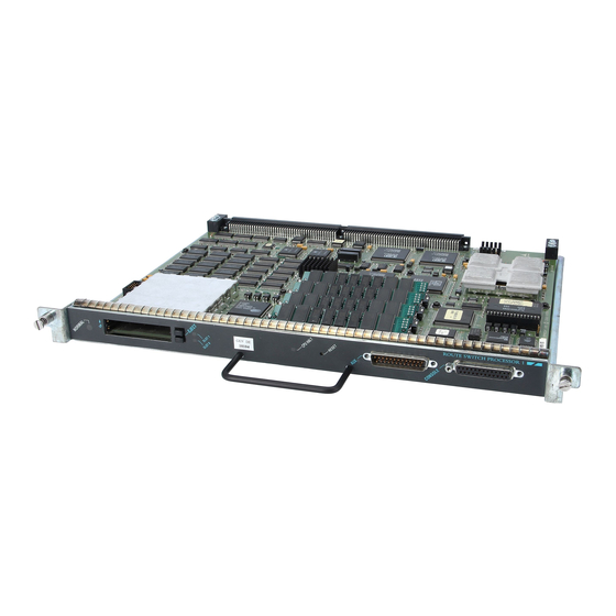
This document discusses the Route Switch Processor (RSP1), which is a main processor module for
the Cisco 7505 router. The RSP1 combines all of the switched routing and high-speed switching
functions required by the Cisco 7505 router. Refer to the section "What Is the RSP1?" on page 3.
Document Contents
Following are the sections in this document:
•
•
•
•
•
•
•
Copyright © 1996
Cisco Systems, Inc.
All rights reserved.
What Is the Cisco 7505?, page 2
What Is the RSP1?, page 3
Prerequisites, page 6
Installation, page 14
Troubleshooting the Installation, page 19
Reference Information, page 23
Cisco Connection Online, page 44
1
Advertisement
Table of Contents

Related Manuals for Cisco RSP1


Summary of Contents for Cisco RSP1
- Page 1 This document discusses the Route Switch Processor (RSP1), which is a main processor module for the Cisco 7505 router. The RSP1 combines all of the switched routing and high-speed switching functions required by the Cisco 7505 router. Refer to the section “What Is the RSP1?” on page 3. Document Contents Following are the sections in this document: •...
- Page 2 DC OK LED. When facing the interface processor end of the chassis, the RSP1 slot is at the top. The four interface processor slots are numbered from slot 0 (the bottom slot) through slot 3 (second slot from the top).
- Page 3 RSP1, in the form of a single in-line memory module (SIMM), or on up to two Personal Computer Memory Card International Association (PCMCIA) cards (called Flash memory cards) that insert in the two PCMCIA slots (slot 0 and slot 1) on the front of the RSP1. (See Figure 9.)
-
Page 4: Memory Components
What Is the RSP1? Memory Components Figure 2 shows the various types of memory components on the RSP1, and Table 1 lists the functions of each type. Figure 2 Route Switch Processor (RSP1) Bus connector DRAM SIMMs ROM monitor Bank 0... - Page 5 128-kilobyte (KB), nonvolatile random-access memory (NVRAM), which is backed up with built-in lithium batteries that retain the contents for a minimum of five years. When replacing an RSP1, be sure to back up your configuration to a remote server so you can retrieve it later.
-
Page 6: Serial Ports
Prerequisites Serial Ports Two asynchronous serial ports on the RSP1, the console and auxiliary ports, allow you to connect external devices to monitor and manage the system. The console port is an Electronics Industries Association/Telecommunications Industry Association (EIA/TIA)-232 receptacle (female) that provides a data circuit-terminating equipment (DCE) interface for connecting a console terminal. - Page 7 ESD voltages on the body; ESD voltages on clothing can still cause damage. Caution For safety, periodically check the resistance value of the antistatic strap. The measurement should be between 1 and 10 megohms. Route Switch Processor (RSP1) Installation and Configuration...
-
Page 8: Compatibility Requirements
Prerequisites Compatibility Requirements You must install the RSP1 in the top slot (slot 4) of the Cisco 7505. (See the section “What Is the Cisco 7505?” on page 2.) You must obtain the replacement SIMMs from an approved vendor. To... - Page 9 U17 on the RSP1). If you upload (copy) the configuration file to a remote server before removing the RSP1, you can retrieve it later and write it into NVRAM on the new RSP1. If you do not upload Route Switch Processor (RSP1) Installation and Configuration...
- Page 10 This procedure is not necessary if you are temporarily removing an RSP1 that you will reinstall; the lithium batteries will retain the configuration in memory until you replace the RSP1 in the system.
- Page 11 Before you upload (copy) the running configuration to the TFTP file server, ensure the following: • You have a connection to the router either with a console terminal connected to the RSP1 console port, or remotely through a Telnet session.
- Page 12 Downloading (Retrieving) the Configuration File After you install the new RSP1, you can retrieve the saved configuration and copy it to NVRAM. To retrieve the configuration, enter configuration mode and specify that you will configure the router from the network.
- Page 13 [timed out] or [failed] indicate a failure (which would probably be due to a network fault or an incorrect server name, address, or filename). The following is an example of a failed attempt to boot from a remote server: Booting Router-confg ..[timed out] Route Switch Processor (RSP1) Installation and Configuration...
-
Page 14: Installation
“Software Prerequisites” and “Microcode Prerequisites” on page 8. The OIR feature allows you to remove and install interface processors without turning off system power. However, you must shut down the system before removing or installing the RSP1, which is a required system component. - Page 15 Installation Each RSP1 and interface processor contains a bus connector with which it connects to the system backplane. The bus connector is a set of tiered pins, in three lengths. The pins send specific signals to the system as they make contact with the backplane.
- Page 16 Removing the RSP1 When you remove or install the RSP1, be sure to use the ejector levers, which help to ensure that the RSP1 is fully inserted in the backplane or fully dislodged from it. Any RSP1 or interface processor that is only partially connected to the backplane can halt the system.
- Page 17 Installation Place the back of the RSP1 in the top slot and align the notches along the edge of the carrier Step 3 with the grooves in the slot. (See Figure 3a.) Figure 3 Ejector Levers and Captive Installation Screw...
-
Page 18: Restarting The System
To prevent damage to the backplane, you must install the RSP1 in the top slot of the Caution Cisco 7505. (See Figure 2 on page 4.) The slots are keyed for correct installation. Forcing the RSP1 into a different slot can damage the backplane and the RSP1. -
Page 19: Troubleshooting The Installation
System Power LEDs On the Cisco 7505, the DC OK LED is located on the lower right of the interface processor end of the chassis and is labeled DC OK. (See Figure 1 on page 2.) If the DC OK LED does not go on or stay on, there is most likely a problem with the input power or one of the internal DC lines. -
Page 20: System Startup Sequence
Figure 4 Route Switch Processor LEDs Caution The reset switch (see Figure 4) resets the RSP1 and the entire system. To prevent system errors and problems, use it only at the direction of your service representative. Interface Processor LEDs Each interface processor contains an enabled LED. The enabled LED goes on to indicate that the interface processor is operational and that it is powered up. - Page 21 When you have verified that the power supply is functioning properly, observe the LEDs on the RSP1. The CPU halt LED on the RSP1 should always remain off. If it goes on during the startup sequence, the system has encountered a processor hardware error.
- Page 22 — If the enabled LEDs on the interface processors go on, the system has booted successfully and is now functional. — If the RSP1 LEDs previously indicated a successful system boot, but none of the enabled LEDs on the interface processors go on, suspect that one of them has shifted out of its backplane connector and halted the system.
-
Page 23: Reference Information
Data Carrier Detect (always on) Auxiliary Port Signals The auxiliary port on the RSP1 is an EIA/TIA-232 DTE, DB-25 plug to which you can attach a CSU/DSU or other equipment in order to access the router from the network. Table 3 lists the EIA/TIA-232 signals used on this port. - Page 24 Replacing and Upgrading DRAM SIMMs The system DRAM resides on up to four SIMMs on the RSP1. The DRAM SIMM sockets are U4 and U12 for bank 0, and U18 and U25 for bank 1. The default DRAM configuration is 16 MB (two 8-MB SIMMs in bank 0).
- Page 25 Place the RSP1 on an antistatic mat or pad, and ensure that you are wearing an antistatic device, such as a wrist strap. Position the RSP1 so that the handle is away from you and the edge connector is toward you—opposite of the position shown in Figure 2 on page 4.
- Page 26 Step 7 Repeat Steps 4 through 6 for the remaining SIMMs, as required for your upgrade. This completes the SIMM removal procedure. Proceed to the next section to install the new SIMMs. 26 Route Switch Processor (RSP1) Installation and Configuration...
- Page 27 Figure 7 Handling a SIMM Follow these steps to install the new SIMMs: Ensure that the RSP1 is in the same orientation as the previous procedure (with the handle Step 1 away from you and the edge connector toward you).
- Page 28 Routers with 128 MB of DRAM will take longer to boot than those with 16 MB of DRAM. This completes the SIMM replacement procedure. To replace the RSP1 in the chassis, proceed to the section “Replacing the RSP1” on page 16, and then restart the system for an installation check.
- Page 29 At the privileged-level system prompt (router #), enter the command. configure terminal You will be prompted as shown in the following example: Router# conf t Enter configuration commands, one per line. End with CNTL/Z. Router(config)# Route Switch Processor (RSP1) Installation and Configuration...
- Page 30 Flash memory and to ignore Break at the next reboot of the router: Router# conf term Enter configuration commands, one per line. End with CNTL/Z. Router(config)# config-register 0x102 Router(config)# boot system flash [filename] Crtl-z Router# 30 Route Switch Processor (RSP1) Installation and Configuration...
- Page 31 The server creates a default boot filename as part of the automatic configuration processes. To form the boot filename, the server starts with the name cisco and adds the octal equivalent of the boot field number, a hyphen, and the processor-type name. Table 7 lists the default boot filenames or actions for the processor.
- Page 32 Copying a new image to Flash memory might be required whenever a new image or maintenance release becomes available. You cannot copy a new image into Flash memory while the system is running from Flash memory. 32 Route Switch Processor (RSP1) Installation and Configuration...
- Page 33 CCCCCCCCCCCCCCCCCCCCCCCCCCCCCCCCCCCCCCCCCCCCCCCCCCCCCCCCCCCCCCCCCCCCCCCCCC Router# Additional Commands Associated to Flash Memory Following are additional commands related to the Flash memory on the RSP1 and the Flash memory cards. You can determine which memory media you are accessing using the pwd command as follows:...
-
Page 34: Recovering A Lost Password
(^[) and then proceed to Step 5. Step 5 Within 60 seconds of turning on the router, press the Break key. This action causes the terminal to display the bootstrap program prompt: rommon 1 > 34 Route Switch Processor (RSP1) Installation and Configuration... - Page 35 Enter the show configuration EXEC command to display the enable password in the configuration file. Enter the configure terminal command at the EXEC prompt. You are prompted as follows: Step 12 Router# configure terminal Enter configuration commands, one per line. End with CNTL/Z. Router(config)# Route Switch Processor (RSP1) Installation and Configuration...
-
Page 36: Using Flash Memory Cards
PCMCIA-based Flash memory for your system. You can use this Flash memory to store and run Cisco IOS images, or as a file server for other routers to access as clients. Occasionally, it might be necessary to remove and replace Flash memory cards; however, removing Flash memory cards is not required and is not recommended after the cards are installed in the slots. - Page 37 Replacing a Flash Memory Card It might become necessary for you to replace or install a Flash memory card in your RSP1. The RSP1 has two PCMCIA slots: slot 0 (bottom) and slot 1 (top). (See Figure 9.) The following procedure is generic and can be used for a Flash memory card in either slot position.
- Page 38 Reference Information Figure 9 Installing and Removing a Flash Memory Card 38 Route Switch Processor (RSP1) Installation and Configuration...
- Page 39 Before you can use a Flash memory card that was previously used on a Route Processor (RP) in a Cisco 7000 series router, you must reformat the Flash memory card. Flash memory cards formatted on RP-based (Cisco 7000 series) routers will not work properly in RSP-based (Cisco 7500 series) routers.
- Page 40 • You have an RSP1 with a good image in the onboard Flash SIMM so you can start the router • The bootable image you want to copy to the Flash memory card exists on a TFTP server to which...
- Page 41 Router(config)# no boot system Router(config)# boot system flash slot0:new.image Crtl-z Router# copy running-config startup-config Router# reload When the system reloads, it will boot the image new.image from the Flash memory card in slot 0. Route Switch Processor (RSP1) Installation and Configuration...
- Page 42 Reference Information Copying Bootable Images Between Flash Memory Cards As future releases of Cisco IOS images become available, you will receive these images either as a netbooted file, a file on floppy disk, or a file on a Flash memory card.
- Page 43 The only way to recover from locked blocks is by reformatting the Flash memory card with the format command. Formatting a Flash memory card will cause existing data to be lost. Caution Route Switch Processor (RSP1) Installation and Configuration...
-
Page 44: Cisco Connection Online
Grand, Grand Junction, Grand Junction Networks, the Grand Junction Networks logo, IGRP, Kalpana, the Kalpana logo, LightStream, Personal Ethernet, and UniverCD are registered trademarks of Cisco Systems, Inc. All other trademarks, service marks, registered trademarks, or registered service marks mentioned in this document are the property of their respective owners.