Table of Contents
Advertisement
Quick Links
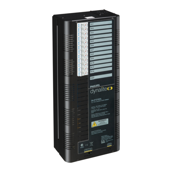
DLE1210GL
12 x 10A Leading Edge Dimmer
Installation Manual
Warning..................................................... 2
Features..................................................... 2
Important Safeguards................................... 2
Internal View............................................... 3
Mounting.................................................... 4
Supply & Load Cable Connections................... 5
Connecting Serial Control Cables.................... 6
Hardware Controls........................................ 7
WMGD Pty Limited trading as Dynalite ABN 33 097 246 92
Unit 6, 691 Gardeners Road Mascot NSW 2020 Australia
t +61 8338 9899
f +61 2 8338 9333
contents
Dimmable Lamps Chart................................. 7
Hold Down Programming Of Presets................ 9
One Touch Button Operation.......................... 9
Troubleshooting........................................... 10
Specification............................................... 10
Useful DyNet Op Codes............................... 11
dynalite.info@philips.com
dynalite-online.com
Advertisement
Table of Contents

Related Manuals for Philips dynalite DLE1210GL


Summary of Contents for Philips dynalite DLE1210GL
-
Page 1: Table Of Contents
Connecting Serial Control Cables……………….. 6 Useful DyNet Op Codes…………………………. 11 Hardware Controls…….……………………….….. 7 WMGD Pty Limited trading as Dynalite ABN 33 097 246 92 Unit 6, 691 Gardeners Road Mascot NSW 2020 Australia t +61 8338 9899 f +61 2 8338 9333 dynalite.info@philips.com dynalite-online.com... -
Page 2: Warning
important safeguards Warning Warning – This is a class A product. In a domestic environment this product may cause radio interference, in TO REDUCE THE RISK OF FIRE OR which case the user may be required to take adequate ELECTRIC SHOCK, DO NOT EXPOSE measures. -
Page 3: Internal View
internal view For spare parts, please call your nearest Dynalite Customer Service Centre, and specify: DLE1210GL DLE1210GL Installation Manual Rev H.docx... -
Page 4: Mounting
mounting Select A Suitable Location This device is designed for indoor use only. If installing in an external location, the DLE1210GL must be housed in a suitable well ventilated enclosure. Choose a dry location that will be accessible after the installation is complete. -
Page 5: Supply & Load Cable Connections
supply & load cable connections Supply Cables The supply input terminals are located toward the centre of the enclosure and consists of Earth, Neutral, and Phase, all of which will accept up to 16mm cables. The supply cables should have a capacity of 75A, to allow the device to be loaded to its maximum capacity. -
Page 6: Connecting Serial Control Cables
connecting serial control cables Connect Data Cable in a ‘Daisy Chain’ Determine Your Requirements Serial ports are used to interconnect other dimmers, smart control panels, sensors and AV controllers. Serial port devices can be identified by 4 terminals, labelled: GND, DATA+, DATA-, +VE. Serial Cable Connections There is one RS485 port for DyNet signals, in the form of a RJ12 socket, on the front panel, which is... -
Page 7: Hardware Controls
Diagnostic Information AUX Input - This is a dry contact interface that is active low. The dry contact is connected between the AUX and GND terminals on the DyNet connector strip. The function of the AUX input is programmable. Ensure that the cable length between the dry contact and terminal strip is no longer than 2 metres. -
Page 8: Preset Programming Using The Program Key
Dynalite Intelligent Light Pty Ltd. Not to be reproduced without permission. Unit 6, 691 Gardeners Road Mascot NSW 2020 Australia Tel: +61 2 8338 9899 Fax: +61 2 8338 9333 E-mail: dynalite.info@philips.com Web: Philips.com/dynalite DLE1210GL Installation Manual Rev H.docx...