Table of Contents
Advertisement
Advertisement
Table of Contents

Related Manuals for Philips OccuSwitch DALI LRM2070

Summary of Contents for Philips OccuSwitch DALI LRM2070
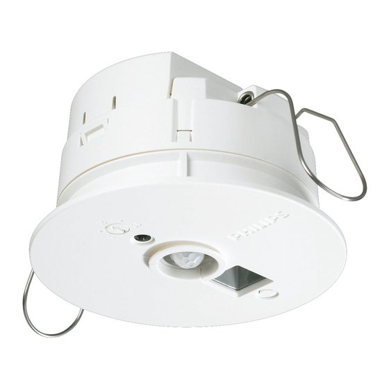
- Page 1 OccuSwitch DALI User Guide OccuSwitch DALI...
-
Page 2: Table Of Contents
OccuSwitch DALI User Guide Page 2 Table of Contents Introduction to the OccuSwitch DALI . . . . . . . . . . . . . . . . . . . . . . . . . . . . . . . . . . . . . . . . . . . 5 Operating principle . - Page 3 OccuSwitch DALI User Guide Page 3 3 .2 .2 Type of OccuSwitch DALI . . . . . . . . . . . . . . . . . . . . . . . . . . . . . . . . . . . . . . . . . . . . . 24 3 .3 Selecting the OccuSwitch DALI mode .
- Page 4 OccuSwitch DALI User Guide Page 4 5 .2 .2 Shared Occupancy Control . . . . . . . . . . . . . . . . . . . . . . . . . . . . . . . . . . . . . . . . . . . 37 5 .3 Using a universal DALI gateway .
-
Page 5: Introduction To The Occuswitch Dali
IP rating is IP20 . For (semi) outdoor applications where higher IP ratings are required, Philips Lighting can provide other solutions . The OccuSwitch DALI dimming system is a combination of daylight depending regulation, occupancy control and manual control . - Page 6 OccuSwitch DALI User Guide Page 6 Feature Description Number of drivers per OccuSwitch DALI Maximum of 15 drivers per OccuSwitch DALI . Parallel linking Maximum of 22 OccuSwitch DALI (Advanced) linked in parallel . Detection area Minor movement detection area is 4x5 meter . Major movement detection area is 6x8 meter .
-
Page 7: Operating Principle
Standalone system with 2 DALI output connectors for Basic window and corridor installation . LRM2072 OSD Basic NB Exactly like LRM2070 but without the Philips wordmark on the front plate LRM2080 OccuSwitch DALI Standalone system with 2 DALI output connectors . - Page 8 OccuSwitch DALI User Guide Page 8 The following accessories are available for the OccuSwitch DALI lighting dimming system: OccuSwitch DALI accessory Description LRM8118 ActiLume The LRM8118 can extend the movement detection area Extension sensor of OccuSwitch DALI: it has the same detection area size as the OccuSwitch DALI .
-
Page 9: Occuswitch Dali Basic (Lrm207X)
OccuSwitch DALI User Guide Page 9 2 . 1 . 1 OccuSwitch DALI Basic (LRM207x) Example Figure 1 shows an example layout of two simple cell offices: The left example uses the two outputs (DA and X) for the window and corridor row . -
Page 10: Occuswitch Dali Advanced (Lrm208X)
OccuSwitch DALI User Guide Page 10 2 . 1 .2 OccuSwitch DALI Advanced (LRM208x) Example Figure 2 shows an example with a larger room existing of two office grids with each their own OccuSwitch DALI . The two devices are connected via parallel linking, so they can share their occupancy status with each other . -
Page 11: Occuswitch Dali Bms (Lrm209X)
OccuSwitch DALI User Guide Page 11 2 . 1 .3 OccuSwitch DALI BMS (LRM209x) Example Figure 3 shows an example layout of two cell offices . Each office part has its own OccuSwitch DALI BMS and two rows of luminaires (a window row and a corridor row) . The OccuSwitch DALI devices are connected to a BMS system . -
Page 12: Extension Movement Sensor (Lrm8118)
OccuSwitch DALI User Guide Page 12 2 . 1 .4 Extension movement sensor (LRM8118) Figure 4: OccuSwitch DALI with an extension movement sensor The extension sensor (LRM8118) allows extension of the detection area of any OccuSwitch DALI . The sensor is connected to the same DALI line as the luminaires . - Page 13 OccuSwitch DALI User Guide Page 13 LCU2070/ LRM8119 LRM8118 LRM8118 Max. # LCU2070/ LRM8119 LRM8118 LRM8118 Max. # LCU2071 with with drivers LCU2071 with with drivers LED on LED off LED on LED off Table 7: The maximum number of devices that can be connected in combination with extension sensors DA connection X connection...
-
Page 14: Luminaire Control
OccuSwitch DALI User Guide Page 14 Luminaire control The window (DALI group 1) and corridor (DALI group 2) 2 .2 . 1 DALI group assignment side speak for itself, but the additional groups are not so The OccuSwitch DALI can address four different groups of obvious . -
Page 15: Daylight Dependent Regulation
This default can be overridden, in order to turn the specifications as the standard sensor . corridor row off as well . For this special case, please contact your local Philips representative for details . D Note It is possible to limit the detection area of the In the daylight override function, the lights will switch movement sensor with a retractable shield . -
Page 16: Local Control
OccuSwitch DALI User Guide Page 16 2 .3 .3 Local control 2 .3 .4 Infrared group addressing The OccuSwitch DALI can be locally controlled using IR The OccuSwitch DALI contains an infrared receiver that remotes and (with the LCU2070 PBU) normal pushbutton enables manual (remote) control of the system . -
Page 17: Manual Control On Ir Channels
Table 10: Manual control channels By default the remote control IRT8050 and IRT9010 are For details please contact your Philips representative . set to channel 1, simultaneously controlling window, corridor and additional presence luminaires . Only the IRT8050 can be configured to use other channels . For setting the infrared channels, see the datasheets of this remote . -
Page 18: Manual Control With The Irt8050
OccuSwitch DALI User Guide Page 18 2 .3 . 7 Manual control with the IRT8050 The IRT8050 can be used in many configurations . The table below shows the most common configurations . The application function and the relation to the DIP switches in the IRT8050 are listed below . -
Page 19: Local Control With Standard Switches And The Lcu2070
OccuSwitch DALI User Guide Page 19 2 .3 .8 Local control with standard switches and the LCU2070 The LCU2070 push button interface makes it possible to connect any type of push button to the OSD system . The connection is simple, connect the interface (with the black wires) to the DALI line, and connect 1 till 4 switches to the unit . -
Page 20: Presets
OccuSwitch DALI User Guide Page 20 2 .3 .9 Presets 2 .3 . 1 0 Local control of multiple OccuSwitch DALI Presets are used to recall pre-programmed light scenes . Sometimes it is required that two OSD units are controlled Selecting presets is possible with remotes IRT8030, by one user interface . -
Page 21: Application Design
. meters, the detection area is significantly smaller . 2 Choose the OccuSwitch DALI type(s) to use: stand- Please contact your local Philips representative for the alone, linked or controlled from a central building exact dimensions . - Page 22 DALI or extension sensor in an installation drawing, note the direction of the detection area . The OccuSwitch DALI or extension sensor must be placed according to this direction . To do this alignment, the “Philips” wordmark and the sensor line-up can be used .
-
Page 23: Selecting The Occuswitch Dali Type
OccuSwitch DALI User Guide Page 23 Selecting the OccuSwitch DALI type In a larger room, multiple detection or control areas are When the detection areas are known, you should define needed . These detection areas must be grouped into which sensor to use for each area: an OccuSwitch DALI application areas: Basic, OccuSwitch DALI Advanced, OccuSwitch DALI BMS, •... -
Page 24: Type Of Occuswitch Dali
OccuSwitch DALI User Guide Page 24 3 .2 .2 Type of OccuSwitch DALI • If the OccuSwitch DALI BMS is used, the OccuSwitch After defining for each area whether an OccuSwitch DALI DALI will communicate with a DALI-capable building or an extension sensor is used, you can select for each management system OccuSwitch DALI which model to use, depending on the need for communication with any neighboring application... -
Page 25: Parallel Operation And Open Plan Mode (Mode 9) Lrm208X Only
If the required set of parameters is not listed as one of the modes 1-9, you may select to use a custom application mode, which is mode 10 . For more information on using this custom mode, please contact your Philips representative . - Page 26 OccuSwitch DALI User Guide Page 26 Mode 9 is a special mode for this parallel operation . The If the person moves to another section, lights in that grid OSD will now make a difference if it detects occupancy will dim up to nominal level . In the vacated area lights will by itself or when it gets a message from its neighbor .
- Page 27 OccuSwitch DALI User Guide Page 27 Occupancy related Daylight level related Cell office Enabled Enabled Local Enabled Enabled Disabled Enabled occupancy Open plan office Enabled Enabled Local Enabled Enabled Disabled Enabled occupancy Class room Disabled Enabled Local Enabled Enabled Enabled Disabled occupancy Cell office with-...
-
Page 28: Commissioning
OccuSwitch DALI User Guide Page 28 Commissioning The physical installation of the OccuSwitch DALI system is described in quick start guide (that comes with the product) and the OccuSwitch DALI datasheet . Once installed, the OccuSwitch DALI system is ready to be used in its default mode . -
Page 29: Configure Controls And Switches
OccuSwitch DALI User Guide Page 29 Configure controls and switches 4 . 1 . 1 IRT8050 This section describes how to set the infrared group and In order to avoid that all lighting circuits in one room channel settings for Infrared remote controls IRT8050 and are switched unintentionally, the transmitters present in IRT9010 . -
Page 30: Irt9010
OccuSwitch DALI User Guide Page 30 4 . 1 .2 IRT9010 The group address of the IRT9010 can be set by pressing simultaneously 2 buttons for 5 seconds . The “Off” button together with the “Dim up” button will set the remote into IR group A . -
Page 31: Configure The Occuswitch Dali
OccuSwitch DALI User Guide Page 31 Configure the OccuSwitch DALI D Notes 4 .2 . 1 Checks • At all actions, stay close to the OccuSwitch DALI and Make sure that the OccuSwitch DALI system has been point the remote control towards the sensor . installed correctly, by checking the LEDs and luminaires •... - Page 32 OccuSwitch DALI User Guide Page 32 Manual calibration with the push button and current Automatic calibration with the push button and installed light level light level The following tools are required for this method: The following tools are required for this method: •...
-
Page 33: 100 Hour Burn-In Mode
OccuSwitch DALI User Guide Page 33 Calibration with remote control 4 .2 .6 Request application mode The OccuSwitch DALI controller has 10 pre-defined 1 Place a light meter on a representative application Modes . The default application mode is Mode I/ II place . -
Page 34: Set Application Mode
OccuSwitch DALI User Guide Page 34 4 .2 .8 Set application mode 4 .2 .9 Background level The OccuSwitch DALI controller has 10 pre-defined In some application modes, the light level of all outputs application modes . The default application mode is is set to a “background”... -
Page 35: Power-Up State
OccuSwitch DALI User Guide Page 35 4 .2 . 1 0 Power-up state 4 .2 . 1 1 Infrared group address The power-up state defines what action the OccuSwitch The Infrared group address (group A, B, C, D, E, F or G) of DALI takes after a power-up or a power interrupt: each OccuSwitch DALI controller can be set by means of •... -
Page 36: Reset To Factory Defaults
OccuSwitch DALI User Guide Page 36 Reset to factory defaults Walk test The OccuSwitch DALI system can be set to default factory To check that the OccuSwitch DALI system is correctly settings (out of the box settings) using the installed and commissioned, the OccuSwitch DALI system IRT9090 . -
Page 37: Occuswitch Dali Bms (Lrm2090 And Lrm2092)
DALI device (in this case the OSD), but they systems rely on the value in the last command given . So a read- • Via a specific gateway (Loytec Lon and BACnet, Philips back of the value will not report the actual status of the KNX and Dynet) OSD . -
Page 38: Using A Universal Dali Gateway
. If occupancy sharing is enabled (please refer to the OSD and the luminaires function separately from this your Philips representative for more information how to connection . All limitations seen by the DALI controller are enable this feature and the tool you require for this) each not present with the gateway . -
Page 39: Occupancy Signal
OccuSwitch DALI User Guide Page 39 5 .4 .2 Occupancy signal 5 .4 .5 OccuSwitch DALI The gateway will translate the occupancy control signal Install the OccuSwitch DALI (OSD) as indicated in the OSD as used between the OSD units itself to the BMS system . documentation as usual (zie OSD documentation) . -
Page 40: The Gateway
OccuSwitch DALI User Guide Page 40 5 .4 .6 The gateway The diagram shows the OSD’s connected to the gateway (in this case the 4 channel LDALI BACnet version) . B Warning The LDALI gateways will recognize the OSD unit both as sensor as well as driver (DALI slave) . -
Page 41: How Does The Osd React To Dali Commands
OccuSwitch DALI User Guide Page 41 How does the OSD react to DALI commands? The table below shows the reaction of the OSD and the luminaires behind it on the most common DALI commands in comparison with a “normal” driver . DALI command Effect on normal driver Effect OSD... -
Page 42: Dali Grouping And Occupancy Control
OccuSwitch DALI User Guide Page 42 DALI grouping and occupancy control Each group shares occupancy . The OSD uses DALI group addressing for occupancy Take for instance group 5 . It exists of 2 OSD units . When control . This is the DALI group address of the unit itself (so one the units detects movement a message with group on the X interface) . -
Page 43: Corridors
RF channel enable this feature a special remote is needed . Please number . scene consult your local Philips sales representative for further information on this . D Note It is not possible to assign a “Short address” to the LRM209x by means of the IRT9090 or any other IR transmitter . -
Page 44: Command List
OccuSwitch DALI User Guide Page 44 5.11 Command list LRM2090 DALI commands Executed for all OSD slave luminaires the same Executed Hex # Command Other — Direct arc Will not clip to min level Extinguish the lamp without fading Dim up 200 ms using the selected fade rate Dim down 200 ms using the selected fade rate Set the actual arc power level one step... - Page 45 OccuSwitch DALI User Guide Page 45 LRM2090 DALI commands Executed for all OSD slave luminaires the same Executed Hex # Command Other Store the value in the DTR as the maximum level Store the value in the DTR as the minimum level Store the value in the DTR as the system failure level...
- Page 46 OccuSwitch DALI User Guide Page 46 LRM2090 DALI commands Executed for all OSD slave luminaires the same Executed Hex # Command Other Check if the slave is in reset state YES/NO Check if the slave is missing a short address YES/NO Returns the version number as XX XX Returns the content of the DTR as XX XX...
- Page 47 OccuSwitch DALI User Guide Page 47 LRM2090 DALI commands Executed for all OSD slave luminaires the same Executed Hex # Command Other Returns the high bits of the random address as HH HH Return the middle bits of the random address as MM MM Returns the lower bits of the random address as LL LL...
-
Page 48: Technical Specifications
OccuSwitch DALI User Guide Page 48 Technical Specifications LED feedback The OccuSwitch DALI provides feedback through different blinking patterns of the LED indicator . The following table shows an overview of the possible LED indications . Figure 13: LED indicators of the OccuSwitch DALI Blinking Pattern Color Cause... -
Page 49: Mode Overview
. Separate tables are given for un- commissioned and commissioned systems and there is a table for mode independent parameters . These tables are only to be used by experts, please contact your Philips representative . Un-commissioned system mode overview... - Page 50 OccuSwitch DALI User Guide Page 50 Un-commissioned system mode overview Mode 1 Behavior Range Background timer 0 min 15 min 30 min 60 min 90 min 120 min 150 min Infinite Table 13: Un-commissioned system mode overview (1) = Not applicable for the LRM2070 (2) = Only valid for DALI connection (Designated as DA on the device) (3) = For the LRM2070 the background timer is infinite (4) = Depending on what the base group and secondary group is...
- Page 51 OccuSwitch DALI User Guide Page 51 Commissioned system mode overview Mode 1 Behavior Range Background timer 0 min 15 min 30 min 60 min 90 min 120 min 150 min Infinite Smart timer 0 min 5 min 10 min 15 min Group 1 Range Occupancy mode...
- Page 52 OccuSwitch DALI User Guide Page 52 Commissioned system mode overview Mode 1 Daylight Disabled dependent regulation Enabled Daylight Disabled dependent switching Enabled Smart timer Disabled Enabled Group 2 Range Occupancy mode Disabled Manual on - Auto off Auto on - Auto off Parallel Link Background lighting Application(1)
- Page 53 OccuSwitch DALI User Guide Page 53 Commissioned system mode overview Mode 1 Group 3 Range Occupancy mode Disabled Manual on - Auto off Auto on - Auto off Parallel Link Background lighting Application(1) Local occupancy No Reaction Daylight override Disabled Enabled Daylight Disabled...
- Page 54 OccuSwitch DALI User Guide Page 54 Commissioned system mode overview Mode 1 Daylight override Disabled Enabled Daylight Disabled dependent regulation Enabled Daylight Disabled dependent switching Enabled Smart timer Disabled Enabled Table 14: Commissioned system mode overview (1) = Not applicable for the LRM2070 (2) = For the LRM2070 the background timer is infinite (3) = The setting itself has no function since these modes have an occupancy behavior...
- Page 55 Disabled, -40%, -30%, -20% (default), -10%, 5%, 10%, 15%, 20%, 25%, 30%, 35%, 40%, 45%, 50% Feedback LED** Enabled (default) Disabled Table 15: Mode-independent parameters * Can be changed with the IRT9090 extended IR programming tool ** Cannot be set by a user, please contact your Philips representative .
-
Page 56: Faq
OccuSwitch DALI User Guide Page 56 The LED indicators of the OccuSwitch DALI Can I use just use any BMS gateway to be constantly show red? connected to the ActiLume DALI gen2? For an explanation of the LED indicators, In principle yes, but it depends on what functionality see section 6 . - Page 57 OccuSwitch DALI User Guide Page 57...
- Page 58 3222 636 49465, 28 September 2016 © 2015-2016 Philips Lighting Holding B . V ., all rights reserved . Philips reserves the right to www .philips .com/controls make changes in specifications and/or to discontinue any product at any time without notice or obligation and will not be liable for any consequences resulting from the use of this publication .