Table of Contents
Advertisement
Advertisement
Table of Contents

Related Manuals for Panasonic CQ-MR505N


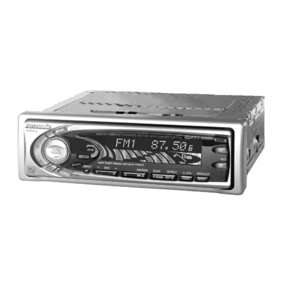
Summary of Contents for Panasonic CQ-MR505N
- Page 17 ¡Label Indications and Their Locations ¡Aanduiding van de labels en hun plaats ¡Warnetiketten und deren Anbringungsort ¡Varningsskyltarna, och deras placering ¡Indications portées les étiquettes et ¡Indicazioni delle etichette e le loro posizioni emplacement ¡Indicaciones de las etiquetas y su ubicación VORSICHT! UNSICHTBARE LASERSTRAHLUNG, WENN ¡APPAREIL À...
- Page 18 Precautions (ISO Connector) ¡Wiring for the power connector conforms to the arrangement of standard ISO connectors. ¡In case of some car types, the arrangement of connector may differ from the standard ISO as shown in Table 1, even though ISO connectors are adopted. Table 1 Fig.
-
Page 19: Laser Products
Panasonic welcomes you to their constantly growing family of electronic products owners. We endeavor to give you the advantages of precise electronic and mechanical engineering, manufactured with carefully selected components, and assembled by people who are proud of the reputation their work has built for our company. -
Page 20: Power And Sound Controls
Power and EO N PT Y Sound R E G Controls Power Turn the key in the ignition until the accessory indicator lights. Press [SOURCE](PWR) to switch on the power. Press and hold [SOURCE](PWR) again for more than 2 seconds to switch off the power. -
Page 21: Audio Mode
(Treble) (Balance) (Fader) SUBW (Sub-Woofer) (Only for CQ-MR505N) Note: In the audio mode (BASS/TREBLE/BALANCE/FADER/SUBW), the display will be back to regular operation mode with no operation for more than 5 seconds (2 seconds in the VOLUME mode). Bass and Treble Press [SEL] to change to the bass (or treble) mode. -
Page 22: Sub-Woofer Volume
(continued) Sub-Woofer Sub-Woofer Volume < > Only for CQ-MR505N (Only for CQ-MR505N) Press [SEL] to change to the Sub-Woofer mode. Press [jVOL] or [iVOL] to increase or decrease the Sub-Woofer volume. Sub-Woofer Volume Level: MUTE (0) to 8 (Default: level 4) -
Page 23: Level Meter
Level Meter Press [SEL] during the display control mode to change to the level meter mode. Press [jTUNE] to change the level meter setting as fol- lows. Select your desired pattern. Pattern 2 Pattern 3 Pattern 1 Pattern Pattern 5 Pattern 4 ([iTUNE]: opposite direction) Dimmer... -
Page 24: Radio Basics
Radio Basics EO N PT Y R E G Tuner Mode Press [SOURCE] to change the source as follows. Radio CD Changer Control (When a disc is inserted) (When a CD Changer is connected) Band Press [BAND] to change the band setting as follows. AM(LW/MW) The stereo indicator lights during reception of an FM stereo broadcast. -
Page 25: Manual Station Preset
Station Preset FM1, FM2, FM3 and AM (LW/MW) can save maximum 6 stations each in their preset station memories. Caution: To ensure safety, never attempt to preset stations while you are driving. Manual Station Preset q Press [BAND] to select a desired band. w Use manual or seek tuning to find a station which is to be preset in the memory. - Page 26 Radio Basics (continued) MONO/LOCAL Selection ¡At the MONO setting, noise is significantly decreased when weak sig- nals are received from an FM broadcast station. ¡ At the LOCAL setting, only strong signals of stations are searched in seek tuning, while at the LOCAL OFF setting, relatively weak signals are also searched.
-
Page 27: Rds (Radio Data System) Reception
RDS (Radio Data System) Reception Many FM stations are broadcasting added data compatible with RDS. This radio set offers convenient functions using such data. AF (Alternative Frequency)r PS (Program Service Name)r When receiving condition becomes poor, an RDS When an RDS station is received, the name of that station automatically displays instead of the fre- station with the same program will be automatically quency. - Page 28 RDS (Radio Data System) Reception (continued) A. Basic Operation in RDS Reception (PS, AF, CT, PI) EO N PT Y R E G RDS Reception Press [AF] when receiving a station in the FM1, FM2 or FM3 band. EO N PT Y ¡...
- Page 29 For Seek Tuning, RDS Station Preset, Tuning in a RDS preset station, and Auto RDS Station Preset, please refer to Radio Basics (pages 16 to 18). RDS seek tuning (PI seek) The PI seek function may be used if an RDS station selected from the memory is poor in receiving condition.
- Page 30 RDS (Radio Data System) Reception (continued) Initial Time Setting Press [BAND] to change to AM mode. q Press [ • ](DISP/CT), “ NO CT” appears on the display. w Press and hold [ • ](DISP/CT) again for more than 2 seconds, “hours” blinks and the time setting mode is activated.
- Page 31 TP Seek Tuning Hold and release Press and hold [jTUNE] or [iTUNE] for more than 0.5 seconds, then release. The seeking automatically stops at the next available TP station. Auto TP Station Preset Press and hold Press and hold [BAND](AUTO•P) for more than 2 seconds. The six strongest available TP stations are automatically saved in the memory on the preset button [1] to [6].
- Page 32 RDS (Radio Data System) Reception (continued) C. PTY Reception (There are some areas where PTY service may not be available.) Switching to PTY Mode EO N PT Y Press [PTY] to select PTY display mode, and the PTY of the broad- R E G cast now received is displayed.
-
Page 33: Program Type Preset
Table of PTY Code and Program Type Press any of the preset buttons [1] to [6] according to your preference. Those buttons already have the program types as follows. (Default set- ting) <Preset PTY> Preset No. Program Type News Speech Sport Pop. -
Page 34: Searching For Pty
RDS (Radio Data System) Reception (continued) Searching for PTY q Select the desired station from preset in the preset number buttons [1] to [6]. Then, the preset PTY and that preset number appear on the display for 5 seconds. Press preset button w While the desired type from 6 presets appears on the display, take either of the following two steps. - Page 35 Mini Disc Player Basics EO N PT Y R E G Mode Selection When a disc is in the deck, press [SOURCE] to change the source as follows. Radio (When a disc is inserted) Track Play CD Changer Control Number Time (When a CD changer is connected) Disc Insert...
- Page 36 Mini Disc Player Basics (continued) Track Search Press and hold ¡Press and hold [2TRACK] or [1TRACK] for more than 0.5 sec- onds to activate fast forward or reverse. ¡Release [1TRACK] or [2TRACK] to resume the normal MD play. Track Repeat ¡Press [6](REP) to repeat the current selection.
-
Page 37: Cd Changer Basics
CD Changer Basics When the unit is connected with a CD text recognizable CD changer (CX-DP9061EN, for example), CD text can appear on the display. Note: CD changer functions are designed for an optional CD changer unit. EO N PT Y R E G Starting the CD Changer Once the CD changer has been connected, press [SOURCE] to change... - Page 38 CD Changer Basics (continued) Track Repeat ¡Press [6](REPEAT) to repeat the current selection. ¡Press [6](REPEAT) again to cancel. Disc Repeat Press and hold ¡Press and hold [6](REPEAT) for more than 2 seconds to repeat the current disc selection. ¡Press [6](REPEAT) again to cancel. Track Random ¡Press [4](RANDOM).
-
Page 39: Changing The Display
Changing the Display Press [•](DISP/CT) to change the display as follows. Disc/Track/Play Time CT Display Track Title Display Disc Title Display When [•](DISP/CT) is pressed for more than 2 seconds while the Track Title or Disc Title appears on the display, the Title display scroll can be switched on or off. -
Page 40: Remote Control Basics
Remove and dispose of an old battery immediately. Battery Information: ¡Battery Type: Panasonic Lithium Battery (CR2025) ¡Battery Life: Approximately 6 months under normal use (at room temperature) Caution: Improper use of batteries may cause overheating, an explosion or ignition, resulting in injury or a fire. -
Page 41: Anti-Theft System
Anti-Theft System This unit is equipped with a removable face plate. By removing this face plate, the radio becomes totally inop- erable. The security indicator will blink. To Remove the Removable Face Plate q Switch off the power. Press w Press [OPEN]. The face plate will be opened. EO N PTY R EG Fig. -
Page 42: Security Indicator
Anti-Theft System (continued) Contact e After fitting the face plate holes, try moving the face plate up and down a few times to make sure that it has been fitted securely. Close the front panel and press the right side of the face plate until a “click” is heard. Fig. -
Page 43: Installation
This product, if possible, should be installed by a professional installer. In case of difficulty, please consult your nearest authorized Panasonic Service Center. 1. This system is to be used only in a 12-volt, DC battery system (car) with negative ground. - Page 44 Installation (continued) ¡When bending the mounting tab of the mounting collar with a screwdriver, be careful not to injure your hands and fingers. ¡We strongly recommend you to wear gloves for installation work to protect yourself from injuries. Installation Procedures Note: Disconnect the cable from the negative (–) battery terminal.
- Page 45 ¡Using the Rubber Cushion (Option) (If there is an existing Rear Support Bracket on the fire wall of car.) Cover Mounting Bolt w on the rear of the unit with Rubber Cushion, and mount it into the exist- ing Rear Support Bracket. Rear Support Bracket (Existing on the car) Rubber Cushion...
-
Page 46: Electrical Connection
Preamp Out Connector (Rear) (Yellow) BATTERY 15A (Orange) (Black) Fuse(15 A) Sub Woofer Out Resistor (1 k ¶ (Red) S.W-OUT (Monaural) (Only for CQ-MR505N Speaker Lead (Dark blue) (Gray w/black stripe) (Violet w/black stripe) (White w/black B (Brown) stripe) (Green (White) (Gray) (Green) - Page 47 (To Motor Antenna) (Max. 500mA) Navi Mute Lead (Orange) This lead is not intended for use with switch Connect to the Navi Mute lead of the Panasonic actuated power antenna. car navigation system (for example, CN- Amp. Relay Control Power Lead (Dark blue) DV2000EN).
-
Page 48: Speaker Connections
Cautions: 1. Use ungrounded speakers only. 2. The speakers to be used with this unit should be able to handle more than 45W(CQ-MR505N), 40W(CQ-MR303N) of audio power. If an optional amplifier is used, the speakers should be able to han- dle the maximum output power of the amplifier. -
Page 49: Maintenance
Use fuses of the same specified rating (15 A). Using different substitutes or fuses with higher ratings, or con- necting the unit directly without a fuse, could cause fire or damage to the unit. If the replacement fuse fails, contact your nearest authorized Panasonic Service Center. Maintenance Your product is designed and manufactured to ensure the minimum of maintenance. - Page 52 E-8496Ab CJ642 SW610 YEAS09267 EJECT D643 LNJ306G5TUWQ EJ. ILL E-8496Aa CJ640 P.GND D641 LNJ306G5TUWQ VDD. 5V FP. OPEN P. LED N. C LCD. CE LCD. CLK LCD.DO 14 13 12 11 10 9 8 LCD.DI INV. GND INV. 10V INV. GND 1 2 3 4 5 6 7...
- Page 58 [E-8496Ab] <TOP VIEW> <BOTTOM VIEW> [E-8496Aa] <TOP VIEW> <BOTTOM VIEW>...
- Page 59 [E-8801A] [E-8801A] [Top View] [Bottom View]...
- Page 60 [E-8802A] [E-8802A] [Top View] [Top View]...
- Page 63 [E-6788Ba][Bottom View]...
- Page 64 [E-6788Ba][Top View] [E-6788Bc][Top View]...