Advertisement
Quick Links
CMA Reverse Installation / CMA 左右反転取付け手順
CMA Mounting Kit / CMA マウントキット
CMA 1U/2U for RMK F1/F2 DROP-IN
English / Deutsch / 日本語
Depending on your order the delivery contents contains different
cable management arms (1 HU or 2 HU). This description applies for
CMA-1U and CMA-2U.
„Reverse Installation": CMA flipped horizontally compared to standard
installation. Cable supplying from the right (Rack front-side view)
a
c
b
g
Mounting the cross bar connector / Querschienenverbinder anbringen / クロスバーコネクタの取り付け
d
b
c
Connecting the CMA stopper / CMA-Stopper anbringen / CMAストッパの取り付け
a
A
b
DOWN
c
Mounting the cross bar / Querschiene anbringen / クロスバーの取り付け
b
c
a
c
left / links / ク ク ク ク ク ク ク ク ク ク 左
(backside view / Ansicht von hinten / ク ク ク ク ク ク ク ク ク ク ラ ック背面)
Preface / Einführung /
Je nach Bestellung sind unterschiedliche Kabelmanagement-
Arme (1 HE oder 2 HE) enthalten. Diese Beschreibung gilt für CMA-
1U und CMA-2U.
„Reverse Installation": CMA horizontal gedreht gegenüber Standard-
montage. Kabelzuführung von rechts (von Rack-Vorderseite betrachtet)
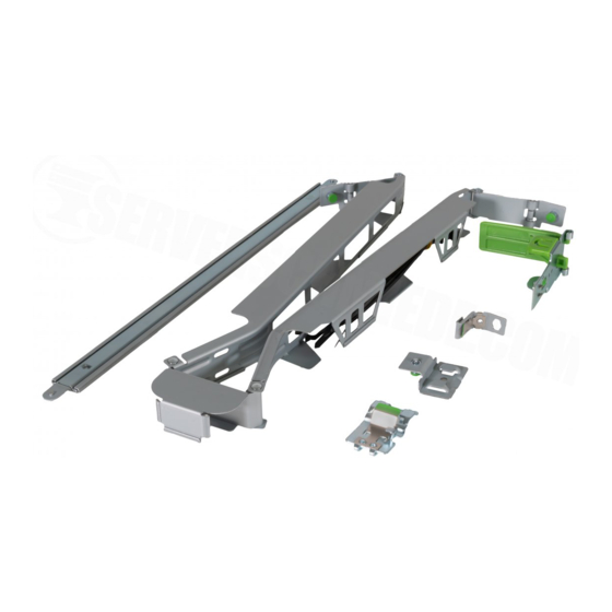
Delivery Contents / Verpackungsinhalt /
d
e
f
h
a
e
d
f
f
d
right / rechts / ク ク ク ク ク ク ク ク ク ク 右
序文
ラックキット梱包物
a CMA (Cable Management Arm)
b CMA stopper with protection cap
c CMA connector outer rail
d CMA connector inner rail
e Cross bar connector
f Cross bar
g Cable ties, 10 cm
h Cable ties, 20 cm
Pull the spring a while placing the cross
►
bar connector on the lever of the middle
rail b.
►
Make sure that the cross bar connector
is positioned flush to the end of the lever
c.
Push the cross bar connector down until
►
it clicks into place. Make sure that there
is no gap at the top
edge d.
Remove the protective cap a while
►
lifting the tongue (A) upwards.
Turn the CMA stopper around
►
b.
►
Reinstall the protective cap on the other
side c.
Hold the cross bar such that the "DOWN"
►
sign d shows toward the CMA stop-
per.
►
Turn the cross bar, position it parallel to
the CMA stopper and insert the rivet into
the keyhole e.
Rotate the CMA stopper through approxi-
►
mately 90° to arrest the rivet f.
►
Hold the cross bar such that the "UP"
sign shows toward the cross bar connec-
tor a.
Position the cross bar parallel to the
►
telescopic rail and insert the rivet into the
keyhole b.
Rotate the cross bar through approxima-
►
tely 90° to arrest the rivet c.
Slide the CMA stopper into the notches
►
of the telescopic rail on the opposite
side until it clicks audibly into place
d.
*A26361-F2735-Z301-1-8N19*
ご 購入された製品によりCMA(ケーブルマネジメントアー ム)
の大きさが異なります(1Uまたは2Uサイズ)。本手順はCMA-
1U (1Uサイズ)及びCMA-2U(2Uサイズ)共通の手順となりま
す。
左右反転取付けについて:左右反転させてご使用した場合、
ラック正面から見て、ケーブルは右側への配線となります。
a CMA (Kabelmanagement-Arm)
b CMA-Stopper mit Schutzkappe
c CMA-Verbinder äußere Schiene
d CMA-Verbinder innere Schiene
e Querschienenverbinder
f Querschiene
g Kabelbinder, 10 cm
h Kabelbinder, 20 cm
Ziehen Sie an der Feder a, während
►
Sie den Querschienenverbinder auf der
Lasche der mittleren Schiene plazieren
b.
Stellen Sie sicher, dass der Querschie-
►
nenverbinder mit dem Ende der Lasche
abschließt c.
►
Drücken Sie den Querschienenverbinder
herunter, bis er einrastet. Stellen Sie
sicher, dass an der Oberkante kein Spalt
entsteht d.
Nehmen Sie die Schutzkappe ab a.
►
Heben Sie dazu die Lasche (A) an.
►
Drehen Sie den CMA-Stopper um b.
Stecken Sie die Schutzkappe auf die
►
andere Seite c.
►
Halten Sie die Querschiene so, dass
die Beschriftung „DOWN" d zum CMA-
Stopper zeigt.
Drehen Sie die Querschiene, positionie-
►
ren Sie sie parallel zum CMA-Stopper
und setzen Sie die Niete in die Schlüssel-
loch-Aufnahme e.
►
Drehen Sie den CMA-Stopper um ca. 90°,
um die Niete zu arretieren f.
►
Halten Sie die Querschiene so, dass die
Beschriftung „UP" zum Querschienenver-
binder zeigt a.
Positionieren Sie die Querschiene parallel zur
►
Teleskopschiene und setzen Sie die Niete in
die Schlüsselloch-Aufnahme b.
►
Drehen Sie die Querschiene um ca. 90°,
um die Niete zu arretieren c.
Schieben Sie den CMA-Stopper in die
►
Aussparungen der Teleskopschiene auf
der gegenüberliegenden Seite, bis sie
hörbar einrastet d.
A26361-F2735-Z301-1-8N19
a CMA (ケーブルマネジメントア
ーム)
b CMAストッパ (保護カバー付き)
c アウター用CMAコネクタ
d インナー用CMAコネクタ
e クロスバーコネクタ
f クロスバー
g ケーブルタイ, 10cm
h ケーブルタイ, 20cm
►
クロスバーコネクタを装着の際
ロックバネを手前(矢印①)に引
きながらインナーレールに装着
します②。
►
装着の際、クロスバーコネクタ
端面とレール端面を合わせま
す。③
►
クロスバーコネクタをカチっと音
がする位置まで押し下げます。
上部④に隙間の無いことを確認
してください。
►
保護カバーのラッチを解除し(A)、保
護カバーを外します①。
►
CMAストッパを反転させます
②。
►
保護カバーを取付けます③。
►
クロスバーの"DOWN"側dをCMA
ストッパに向けます。
►
クロスバーをeのように裏返し,クロ
スバーをCMAストッパと並行にして、
クロスバーコネクタの取付穴に合わ
せて差し込みます。
►
CMAストッパを約90°回転させ
抜け防止リベットで組み付けます
f。
►
クロスバーの"UP"側をクロスバーコ
ネクタに向けます。①
►
クロスバーをレールと並行に向け
て、クロスバーコネクタの取付穴に
合わせて差し込みます。②
►
クロスバーを約90°回転させ
抜け防止リベットで組み付けま
す。③
►
CMAストッパを反対側レールの固
定用ガイドに差し込みカチッと音が
するまでスライドさせて組み付けま
す。④
Advertisement

Related Manuals for Fujitsu CMA


Summary of Contents for Fujitsu CMA
- Page 1 Je nach Bestellung sind unterschiedliche Kabelmanagement- ご 購入された製品によりCMA(ケーブルマネジメントアー ム) cable management arms (1 HU or 2 HU). This description applies for Arme (1 HE oder 2 HE) enthalten. Diese Beschreibung gilt für CMA- の大きさが異なります(1Uまたは2Uサイズ)。本手順はCMA- CMA-1U and CMA-2U. 1U und CMA-2U.
- Page 2 CMAコネクタの固定用ガイドに bis er einrastet. 差し込み、②の方向へカチっと 音がする位置までスライドさせ固 定させます。 Mounted position of the CMA / Montageposition des CMAs / CMAアームの搭載位置 After installation, the CMA should lay on Nach der Installation sollte der CMA wie CMAアームの取付後、CMAアー the crossbar, as shown in the picture.