Fujitsu PRIMERGY CX400 M4 Operating Manual
Server enclosure
Hide thumbs
Also See for PRIMERGY CX400 M4:
- Upgrade and maintenance manual (194 pages) ,
- Operating manual (72 pages) ,
- Disassembly and recycling document (76 pages)

Related Manuals for Fujitsu PRIMERGY CX400 M4


Summary of Contents for Fujitsu PRIMERGY CX400 M4
- Page 1 Operating Manual - English FUJITSU Server PRIMERGY CX400 M4 Server Enclosure Operating Manual March 2019...
- Page 2 – The contents of this manual may be revised without prior notice. – Fujitsu assumes no liability for damages to third party copyrights or other rights arising from the use of any information in this manual. – No part of this manual may be reproduced in any form without the prior written permission of Fujitsu.
- Page 3 Before reading this manual For your safety This manual contains important information for safely and correctly using this product. Carefully read the manual before using this product. Pay particular attention to the accompanying manual "Safety Notes and Regulations" and ensure that these safety notes are understood before using the product.
- Page 4 Please consult the sales staff of Fujitsu if intending to use this product for high safety use. Measures against momentary voltage drop This product may be affected by a momentary voltage drop in the power supply caused by lightning.
- Page 5 Please note that the usage and operation conditions differ depending on the type of HDD used. For more information on the usage and operation conditions of each available type of HDD, see the following internet address: http://jp.fujitsu.com/platform/server/primergy/harddisk/ Operating Manual CX400 M4...
- Page 6 Operating Manual CX400 M4...
-
Page 7: Table Of Contents
Contents Introduction ......9 Notational conventions ..... 9 Before you start . - Page 8 Contents Starting up ......43 Installation steps, overview ....44 Unpacking the server enclosure .
-
Page 9: Introduction
This operating manual is intended for those responsible for installing the hardware and ensuring that the system runs smoothly. It contains all the information you need to put your PRIMERGY CX400 M4 into operation. To understand the various expansion options, you will need to be familiar with the fields of hardware and data transmission and you will require a basic knowledge of the underlying operating system. - Page 10 Introduction Operating Manual CX400 M4...
-
Page 11: Before You Start
Documentation overview To get an overview on all documents on your server, see the following table. All documentation on PRIMERGY hardware and ServerView software is available online from the Fujitsu manuals server at: http://manuals.ts.fujitsu.com For Japan: http://www.fujitsu.com/jp/products/computing/servers/primergy/manual/ The complete PRIMERGY documentation set can also be downloaded as a DVD ISO image at: ftp://ftp.ts.fujitsu.com/images/serverview/manuals... - Page 12 Server Management" user guide Spare parts identification and information system, available for online use or download (Windows OS) at Illustrated Spares catalog http://manuals.ts.fujitsu.com/illustrated_spa or from the CSS component view of the ServerView Operations Manager Glossary Available online Important information on warranty "Warranty"...
-
Page 13: Documents For The Server Nodes
Before you start 2.1.2 Documents for the server nodes Document Description "FUJITSU Server PRIMERGY CX2550 M4 / CX2560 M4 / CX2570 M4 Server Node Operating Manual" Available online "FUJITSU Server PRIMERGY CX2550 M5 / CX2560 M5 / CX2570 M5 Server Node Operating Manual"... - Page 14 Before you start Operating Manual CX400 M4...
-
Page 15: Product Description
This section provides an overview of the server enclosure and information on the features of the PRIMERGY CX400 M4 server enclosure. The PRIMERGY CX400 M4 server enclosure is available as a rack model. Server enclosure The PRIMERGY CX400 M4 server enclosure consists of the server enclosure... -
Page 16: Overview Of The Server Enclosure
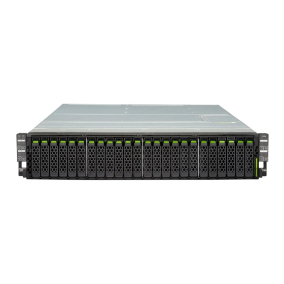
Product description Overview of the server enclosure 3.1.1 Server enclosure front Front overview with CX2550 M4/M5 server nodes Using CX2550 M4/M5 server nodes, the server enclosure can be equipped with up to 8x 2.5-inch HDD/SSD modules. Figure 1: Configuration with CX2550 M4/M5 server nodes Front overview with CX2560 M4/M5 server nodes Using CX2560 M4/M5 server nodes, the server enclosure can be equipped with up to 24x 2.5-inch HDD/SSD modules. - Page 17 Product description Front overview with CX2570 M4/M5 server nodes Using CX2570 M4/M5 server nodes, the server enclosure can be equipped with up to 12x 2.5-inch HDD/SSD modules. Figure 3: Configuration with CX2570 M4/M5 server nodes Pos. Component Operating panel for server node 1 Operating panel for server node 2 Operating panel for server node 3 Operating panel for server node 4...
-
Page 18: Server Enclosure Rear
Product description 3.1.2 Server enclosure rear Rear overview with CX2550 M4/M5 or CX2560 M4/M5 server nodes Figure 4: Configuration with CX2550 M4/M5 or CX2560 M4/M5 server nodes Rear overview with CX2570 M4/M5 server nodes Figure 5: Configuration with CX2570 M4/M5 server nodes Pos. -
Page 19: Features
Product description Features Advanced Thermal Design The Advanced Thermal Design option allows you to operate the system with a wider temperature range of 5 °C to 40 °C, depending on your system and configuration. This option can only be ordered from the manufacturer and is indicated by the respective logo on the identification rating plate. - Page 20 A detailed description of the Security menu and how to assign passwords can be found in the "D385x BIOS Setup Utility for FUJITSU Server PRIMERGY CX2550 M4 / CX2560 M4 / CX2570 M4 Reference Manual"...
-
Page 21: Controls And Indicators
Product description Controls and indicators 3.3.1 Controls and indicators on the server enclosure front 3.3.1.1 Controls on the front panel Figure 6: Controls on the front panel (QRL left and right) Pos. Label Button Function Highlights the ID indicator on the front panel ID button and I/O panel for easy server identification. -
Page 22: Indicators On The Front Panel
Product description 3.3.1.2 Indicators on the front panel Figure 7: Controls on the front panel (QRL left and right) Enclosure-related indicators Pos. Label Indicator Status Description No critical event detected (CSS component). PSU CSS orange Prefailure event detected (CSS indicator component). - Page 23 Product description Pos. Label Indicator Status Description No critical event detected (non CSS component). orange Prefailure event detected (non CSS Global component). Error indicator, Non CSS component failure see also detected. "iRMC- Possible causes: related – System is out of the specified flashing status temperature range...
- Page 24 Product description Node-related indicators Each server node has a separate operation area marked with the corresponding number. In the table above, server node 1 is used as an example Pos. Label Indicator Status Description No critical event detected (non CSS component).
- Page 25 Product description Pos. Label Indicator Status Description – The server node is switched off and connected to the mains (standby mode). – The server node has been switched on but Power Cycle Delay settings delay it from green on turning on for a specified time. After connecting the server to connected the mains, it will take about 60...
- Page 26 An emergency flash of the iRMC firmware is in progress. For more information on the emergency flash of the iRMC firmware, see the "FUJITSU Server PRIMERGY CX2550 M4 / CX2560 flashing blue flashing orange M4 / CX2570 M4 Server Node Upgrade and Maintenance Manual"...
-
Page 27: Indicators On The Hot-Plug Hdd/Ssd Module
Product description 3.3.1.3 Indicators on the hot-plug HDD/SSD module Figure 8: Indicators on the 2.5 inch HDD modules Pos. Label Indicator Status Description The HDD/SSD is inactive. Access indicator green on The HDD/SSD being accessed No HDD/SSD error detected. An HDD/SSD error has been detected. -
Page 28: Controls And Indicators On The Server Enclosure Rear
Product description 3.3.2 Controls and indicators on the server enclosure rear 3.3.2.1 Indicator on hot-plug PSU Figure 9: Indicator on hot-plug PSU Pos. Indicator Status Description flashing The server is switched off, but mains green voltage is present (standby mode). The server is switched on and operating green on properly. -
Page 29: Important Information
Important information Depending on your server enclosure or the installed options some information is not valid for your server enclosure. CAUTION! Before installing and starting up a server enclosure, please observe the safety instructions listed in the following section. This will help you to avoid making serious errors that could impair your health, damage the server enclosure and endanger the data base. - Page 30 Important information Before starting up During installation and before operating the server enclosure, observe the ● instructions on environmental conditions for your server enclosure. If the server enclosure is brought in from a cold environment, condensation ● may form both inside and on the outside of the server enclosure. Wait until the server enclosure has acclimatized to room temperature and is absolutely dry before starting it up.
- Page 31 Important information Always connect the server enclosure and the attached peripheral devices to ● the same power circuit. Otherwise you run the risk of losing data if, for example, the server enclosure is still running but a peripheral device (e.g. memory subsystem) fails during a power outage.
- Page 32 Important information The components marked with a warning notice (e.g. lightning symbol) may ● only be opened, removed or exchanged by authorized, qualified personnel. Exception: CSS components can be replaced. The warranty is void if the server enclosure is damaged during installation or ●...
- Page 33 Important information Batteries must be disposed of in accordance with local regulations concerning special waste. Make sure that you insert the battery the right way round. ● The battery used in this server enclosure may present a fire or chemical burn ●...
- Page 34 Important information Shocks and vibrations are also to be avoided. ● Do not insert any objects other than the specified CDs/DVDs/BDs. ● Do not pull on, press hard, or otherwise handle the CD/DVD/BD tray ● roughly. Do not disassemble the optical disk drive. ●...
- Page 35 Important information You can prevent damage from the optical disk drive and the CDs/DVDs/BDs, as well as premature wear of the disks, by observing the following suggestions: – Only insert disks in the drive when needed and remove them after use.
- Page 36 Important information The circuit boards and soldered parts of internal options are exposed and ● can be damaged by static electricity. To ensure reliable protection, you must wear an earthing band on your wrist when working with ESD modules and connect it to an unpainted, conducting metal part of the server enclosure.
- Page 37 Important information When connecting and disconnecting cables, observe the relevant ● instructions in the "Important Information" chapter of the technical manual for the corresponding rack. The technical manual is supplied with the corresponding rack. When installing the rack, make sure that the anti-tilt mechanism is ●...
-
Page 38: Energy Star
CPU utilization levels. CE conformity The system complies with the requirements of European Regulations. Find the CE declaration on certificate portal: https://sp.ts.fujitsu.com/sites/certificates/default.aspx To open the CE declaration applicable for your system, proceed as follows: Ê Select Industry Standard Servers. -
Page 39: Fcc Class A Compliance Statement
Consult the dealer or an experienced radio/TV technician for help. ● Fujitsu is not responsible for any radio or television interference caused by unauthorized modifications of this equipment or the substitution or attachment of connecting cables and equipment other than those specified by Fujitsu. The correction of interferences caused by such unauthorized modification, substitution or attachment will be the responsibility of the user. -
Page 40: Environmental Protection
Important information Environmental protection Environmentally-friendly product design and development This product has been designed in accordance with the Fujitsu standard for "environmentally friendly product design and development". This means that key factors such as durability, selection and labeling of materials, emissions, packaging, ease of dismantling and recycling have been taken into account. - Page 41 Further information can be found at: http://ts.fujitsu.com/recycling Details regarding the return and recycling of devices and consumables within Europe can also be found in the "Returning used devices" manual, via your local Fujitsu branch, or at: http://ts.fujitsu.com/recycling Operating Manual CX400 M4...
- Page 42 Important information Operating Manual CX400 M4...
-
Page 43: Starting Up
Starting up CAUTION! Follow the safety instructions in chapter "Important information" on ● page Do not expose the server enclosure to extreme environmental ● conditions (see "Ambient conditions" on page 79). Protect the server enclosure from dust, humidity and heat. Make sure that the server enclosure is acclimatized for the time ●... -
Page 44: Installation Steps, Overview
Starting up Installation steps, overview Ê First of all, carefully read the safety instructions, see "Important information" on page Ê Transport the server enclosure to the place where you want to set it up. Ê Unpack the system, check the contents of the package for visible transport damage and check whether the items delivered match the details on the delivery note, see section "Unpacking the server enclosure"... - Page 45 You will find more information on installing the server enclosure remotely or locally in the "ServerView Suite Installation Manager" user’s guide (on the Fujitsu manuals server under x86 Servers - Software - ServerView Suite - Server Installation and Deployment).
-
Page 46: Unpacking The Server Enclosure
Ê Remove all scratching protection foils from the front panel, HDD/SSD frames, Fujitsu and PRIMERGY logo, VGA dummy and ODD dummy in case they are still sticked to the server system. Operating Manual... -
Page 47: Installing/Removing The Server Enclosure In The Rack
If several units are simultaneously extended out of the rack, there is a risk that the rack could tip over. Fujitsu rack systems The rack systems from Fujitsu support the installation of PRIMERGY server enclosures: – PRIMECENTER rack –... - Page 48 The power is supplied via the multiple socket outlets fitted in the rack (not valid for Japan). The main features of Fujitsu rack systems are as follows: – support systems having a linear alignment feature to ensure that they can...
-
Page 49: Installing The Server Enclosure In The Rack
Starting up 5.3.1 Installing the server enclosure in the rack Removing the inner rail from the carrier rails Ê Identify the inner rail and the outer rail. Figure 11: Inner (2) and outer rail (1) Figure 12: Starting position of inner and outer rail Ê... - Page 50 Starting up Figure 13: Turning outer rail Ê Turn the rails to the other side (see arrow). Figure 14: Removing inner rail from outer rail Ê Push the locking latch (1) and pull the outer rail as far as possible towards the front side (2).
- Page 51 Starting up Attaching the carrier rails to the server enclosure Ê Identify the right and the left rail. Figure 15: Attaching the right carrier rail Ê Move the right carrier rail towards the server enclosure and position the holes onto the positioning screws (1).The carrier rail must lock in the corresponding hole.
- Page 52 Starting up Installing the carrier rails Ê Clarify the position of the system unit in the rack. Ê Mark the position of the bottom edge of the server enclosure on the support uprights. Ê Identify the right and the left rail. Figure 17: Attaching the left carrier rail Figure 18: Adjusting the positioning clip Ê...
- Page 53 Starting up Ê Move the left rail towards the front side (4) while holding the positioning clip (3). The mounting aid must lock in the corresponding hole. Ê Release the positioning clip (5) after the designated position is reached. Figure 19: Tightening the M5 screw Ê...
- Page 54 Starting up Installing the server enclosure into the rack CAUTION! At least two people are needed to position the server on the rack rails. (For Japan, see " 安全上のご注意 ".) For configurations below 32 kg: At least two people are needed to lift the server enclosure out of the rack cabinet.
- Page 55 Starting up Figure 20: Mounting the server enclosure into the rack (A). Ê Set the back-end of both inner rails (1) into the front entry of the both outer rails (2). Figure 21: Mounting the server enclosure into the rack (A) Ê...
- Page 56 Starting up Figure 22: Mount the server enclosure in the rack. Ê When the server enclosure is stopped, push the locking latch (1) on both sides and push the server enclosure in the rack (2). Figure 23: Mounting the server enclosure into the rack (B) Ê...
-
Page 57: Removing The Server Enclosure Out Of The Rack
Starting up 5.3.2 Removing the server enclosure out of the rack CAUTION! At least two people are needed to lift the server enclosure out of the rack cabinet. For Japan, according to the following procedures. If you remove the CX400 M4 server enclosure out of the rack, remove all HDD, PSU and server node from the server enclosure. - Page 58 Starting up – The server enclosure weighs more than 21 kg and is installed above the height of 25 U. When using a lifter, this removal procedure needs to be carried out by maintenance personnel. Figure 24: Removing the server enclosure out of the rack (A) Ê...
- Page 59 Starting up Figure 25: Removing the server enclosure out of the rack Ê When the server enclosure is stopped, push the locking latch (1) on both sides and pull the server enclosure out of the rack (2). Figure 26: Removing the server enclosure out of the rack (C) Ê...
-
Page 60: Connecting Cables
Starting up Connecting cables 5.4.1 Notes on connecting/disconnecting cables CAUTION! Always read the documentation supplied with the device you wish to connect. Never connect, or disconnect cables during a thunderstorm. Never pull on a cable when disconnecting it. Always take hold of the cable by the plug. -
Page 61: Connecting The Power Cord
5.4.2 Connecting the power cord The system has two bays for hot-plug PSUs. Each hot-plug PSU can be replaced during operation (see the "FUJITSU Server PRIMERGY CX400 M4 Server Enclosure Upgrade and Maintenance Manual"). CAUTION! The server enclosure is automatically set to a mains voltage in the range 100 - 240 V. - Page 62 Furthermore, Fujitsu cannot be held responsible for any related damage, malfunction, or loss of data, etc. Be sure to wait for 10 seconds or more after shutdown before turning ●...
-
Page 63: Operation
Furthermore, Fujitsu cannot be held responsible for any related damage, malfunction, or loss of data, etc. Be sure to wait for 10 seconds or more after shutdown before turning ●... - Page 64 Operation After connecting the power cord, press the On/Off button after it ● passes for more than 10 seconds. Switching the server node on The AC connected indicator lights up green (standby mode) when the server is connected to the mains. It will take about 60 seconds until the server node can be switched on.
- Page 65 Operation – After power failure The server node automatically reboots following a power failure (depending on the settings in the BIOS or in iRMC S5). – Power button override The server node can be switched off (hard power off) by holding down the On/Off button (approximately 4 - 5 seconds).
-
Page 66: Removing 2.5-Inch Hdd/Ssd Modules
Operation Removing 2.5-inch HDD/SSD modules 6.2.1 Removing a 2.5-inch HDD/SSD module Figure 27: Installing the 2.5-inch HDD/SSD module Ê Pinch the green locking clips (1) and open the locking lever (2). Ê Pull the HDD/SSD module out a few centimeters (3). Ê... -
Page 67: Installing A 2.5-Inch Hdd/Ssd Dummy Module
Operation 6.2.2 Installing a 2.5-inch HDD/SSD dummy module CAUTION! If the removed HDD/SSD module is not replaced immediately, always replace a dummy module into the unused HDD/SSD bay to comply with applicable EMC regulations and satisfy cooling requirements. Figure 28: Installing a 2.5-inch dummy module Ê... -
Page 68: Removing The Hot-Plug Psu
Operation Removing the hot-plug PSU Figure 29: Removing the PSU Ê Push the handle of the PSU halfway upward in the direction of the arrow (1). Ê Press in on the green locking latch (2). Ê While keeping the green locking latch pressed, pull the PSU out of its bay (3). -
Page 69: Installing A Server Node
Operation Installing a server node 6.4.1 Removing the server node dummy module The CX400 M4 system must always run with closed node bays. It is only allowed to leave a bay open for a limited time in case of repairing a server node (for example). - Page 70 Operation Only necessary for CX2550 M4 and CX2560 M4 server nodes! Ê Remove the gasket of the lower server node and keep it for later use. Ê Push the server node at the handle into the server enclosure until the locking mechanism snaps into place.
- Page 71 Operation This is the good case. This is the bad case (gap under the bracket). Operating Manual CX400 M4...
-
Page 72: Installing The Cx2570 M4/M5 Server Node
Operation 6.4.3 Installing the CX2570 M4/M5 server node CAUTION! Follow the safety instructions in the chapter "Important information" ● on page Figure 31: Installing the server node Ê Push the server node at the handle into the server enclosure until the locking mechanism snaps into place. -
Page 73: Cleaning The Server Enclosure
Operation Cleaning the server enclosure CAUTION! Switch the server enclosure off and disconnect the power plugs from the properly grounded power outlets. Do not clean any interior parts yourself; leave this job to a service technician. Do not use any cleaning agents that contain abrasives or may corrode plastic. - Page 74 Operation Operating Manual CX400 M4...
-
Page 75: Troubleshooting And Tips
Ê Contact our customer service team. The meaning of the error message is explained in the documentation for the relevant components and programs, available online at http://manuals.ts.fujitsu.com. Power-on indicator remains unlit after you have switched on your device Cause Troubleshooting Power cable Ê... - Page 76 Ê Remove and reinstall the drive while the system is switched on. If the HDD/SSD continues to be shown as defective, then replace it (see the "FUJITSU Server PRIMERGY CX400 M4 Server Enclosure Upgrade and Maintenance Manual"). Operating Manual...
-
Page 77: Technical Data
Please be forewarned. The data sheets for this server enclosure contain more technical data. The data sheets are available online at: http://www.fujitsu.com/fts/products/computing/servers/primergy For more information, see the Documents tab under for example Rack Servers. For Japan: http://www.fujitsu.com/jp/products/computing/servers/primergy... - Page 78 Technical data Supported capacity RAM CX2550 M4: 2048 GB 2048 GB (max.) CX2550 M5: 3584 GB (Total of DDR4 DIMM and NVDIMM) CX2560 M4: 2048 GB CX2560 M5: 3584 GB (Total of DDR4 DIMM and NVDIMM) Number of storage drives 2x 2.5-inch (applicable to 6x 2.5-inch (max.)
- Page 79 Technical data Ambient conditions Environment class 3K2 EN 60721 / IEC 721 Part 3-3 Environment class 2K2 EN 60721 / IEC 721 Part 3-2 Temperature: Operation (3K2) 10°C ... 40°C (with ATD) 10°C ... 35°C (without ATD) The maximum temperature depends on type of the CPU.
- Page 80 Technical data Compliance with standards Product safety and ergonomics International IEC60950-1 Europe Safety EN 60950-1 EN 50371 EN 50392 Ergonomics ISO 9241-3 EN 2941-3 EK1-ITB 2003:2007 USA / Canada CSA-C22.2 No. 60950-1-07 2ed. UL 60950-1 2ed. Taiwan CNS 14336 China GB 4943 Australia, New Zealand (RCM) CB(IEC60950-1 AS/NZS Deviations.)
- Page 81 Technical data Korea KN 32 / KN 35 CE marking to EU Electromagnetic compatibility 2014/30/EU directives Low Voltage Directive 2014/35/EU Restriction of hazardous substances 2011/65/EC RoHS Compliance EU EN 50581 RoHS Compliance Taiwan CNS 15336 CAUTION! This device meets the requirements of Class A CISPR 22. This device can cause radio interference in residential areas.
- Page 82 Technical data Operating Manual CX400 M4...
-
Page 83: Warranty And Service
Warranty and service Warranty The warranty regulations can be found online at:http://manuals.ts.fujitsu.com under x86 Servers - Safety / Eco / Warranty For Japan: http://www.fujitsu.com/jp/products/computing/servers/primergy/support/ For the warranty regulations select " 製品保証ご案内 ( 無償修理期間 )" Service Telephone numbers of the local service partner can be found online at: http://ts.fujitsu.com/support/servicedesk.html... - Page 84 Warranty and service Bearbeitungsstand Bestellnummer...