
Related Manuals for GE Intellix BMT 330


Summary of Contents for GE Intellix BMT 330
- Page 1 Intellix BMT 330 USER MANUAL GE Energy , Lissue Industrial Estate East, Lissue Road, Lisburn, BT28 2LU, United Kingdom Tel: +44 (0) 28 9262 2915, Fax: +44 (0) 28 9262 2202 E-mail: ge4service@ge.com BMT330UM v1.0 20-Jun-16...
-
Page 2: Table Of Contents
Intellix BMT 330 User Manual ™ Table of Contents INTRODUCTION ..........................5 Product Overview ......................... 5 Scope ..............................5 Abbreviations & Definitions ...................... 6 Warnings & Cautions ........................6 Conventions ........................... 7 Technical Specifications ......................8 Measurements ......................... 8 Environmental .......................... 8 Power............................ - Page 3 Intellix is a registered trademark of General Electric Company. This release of this document is accurate at the time of this writing. General Electric Company reserves the right to change the Intellix BMT 330 and this document without notice. For the latest revision of this manual, visit: http://www.gegridsolutions.com/md/catalog/BMT330.htm...
- Page 4 Intellix BMT 330 User Manual ™ Related Documents Document Title Intellix ™ BMT 330 Pre-Installation Information Intellix ™ BMT 330 Installation Manual Intellix ™ BMT 330 Service Manual Intellix ™ BMT 330 commissioning instructions Intellix ™ BMT 330 Modbus registers list BMT 330 DNP3 Objects &...
-
Page 5: Introduction
Its installation on a PC. The configuration operations after installation of the Intellix™ BMT 330. Monitoring of the data is carried out using GE’s PERCEPTION software (v1.18.2 or above). Please refer to its own user manual. Page 5 BMT330UM v1.0... -
Page 6: Abbreviations & Definitions
Intellix BMT 330 User Manual ™ Abbreviations & Definitions Abbreviation Meaning Current Transformer Intellix™ BMT 330 Partial Discharge and Bushing Monitor LOTO Lock Out, Tag Out procedure Partial Discharge Partial Discharge Intensity Warnings & Cautions The meaning of symbols used on the Intellix™ BMT 330 device: Refer to the Instruction Manual to prevent injury or damage to equipment Hazardous voltages may be present... -
Page 7: Conventions
A procedure, practice, or condition could cause bodily WARNING injury or death Before performing any manipulation with the Intellix BMT 330, ensure you reviewed all the risk associated with the product listed in this manual and the installation manual. Conventions Menu items or options displayed on the display screen are represented in the text in bold, for example Alarm Setup. -
Page 8: Technical Specifications
Intellix BMT 330 User Manual ™ Technical Specifications Measurements Feature Value Maximum Bushing Temperature at 90 deg C (194 deg F) sensor Relative Phase Angle accuracy 0.01 deg of angle Maximum number of PD measured 200 PD per cycle (50 to 60Hz) Maximum PD measurable CAT III. -
Page 9: Power
Intellix BMT 330 User Manual ™ Power Feature Value AC power supply requirement 100 to 240Vac, 50 to 60Hz, 1.24 to 0.41A Output Relays (quantity 3) Single Phase Change Over (SPCO), Maximum RATED: 2A @240VAC resistive load, 2A @ 30VDC Fuse (1 each on Live &... - Page 10 Intellix BMT 330 User Manual ™ Category Standard Class/Level Test IEC 61000-4- X 2.5kV & Oscillatory Wave IEC 61000-3- Pst 10min, Voltage fluctuations & flicker Plt 120min IEC 60255-5 5kV, 2kV & Impulse, Dielectric & Insulation 500Vdc resistance testing Environmental IEC 60068-2- -40 °C Cold...
-
Page 11: Software Installation
Intellix BMT 330 User Manual ™ SOFTWARE INSTALLATION The BMT Setup Software is supplied on a CD. To install the software, load the CD into your PC’s DVD/CD drive, and the installer package should run automatically. If the installer does not run automatically, then use Windows Explorer to view the CD’s directory structure. -
Page 12: Routine User-Level Operations With Intellix
Intellix BMT 330 User Manual ™ ROUTINE USER-LEVEL OPERATIONS WITH Intellix Figure 1 shows a general Single Transformer installation layout with the sensor connections required for the Intellix™ BMT 330. Figure 2 shows a general Bank of 3 Single Phase Transformers general installation layout. The external LED provide information about the CAUTION Intellix™... - Page 13 Intellix BMT 330 User Manual ™ Figure 1: Single Transformer general installation layout Figure 2: Bank of 3 Single Phase Transformers general installation layout Page 13 BMT330UM v1.0 20-Jun-16...
-
Page 14: Connection Of Pc To Intellix™ Bmt 330
Intellix BMT 330 User Manual ™ Connection of PC to Intellix™ BMT 330 The first configuration must be carried out by a direct connection of BMT Setup Software to the Intellix™ BMT 330. To connect a laptop with the BMT Setup Software directly to the Intellix™ BMT 330 use the provided USB to mini-USB cable to connect your laptop to the mini-USB connector on the Intellix™... -
Page 15: Opening The Setup Software
Intellix BMT 330 User Manual ™ After completion of the software setup of the Intellix™ CAUTION BMT 330, remove the PC connection by following the above steps in reverse, eg: Remove the PC connection, Reinstate the Alarm PCB (if applicable), ... - Page 16 Intellix BMT 330 User Manual ™ Figure 4: BMT Setup Software Sign On Screen The available Customer pages are: Communication (page 20). This allows alteration of the Intellix™ BMT 330 setup software basic communication settings to communicate with the Intellix™...
-
Page 17: Changing Between Intellix™ Bmt 330 And Intellix™ Bmt 300 Units
Intellix BMT 330 User Manual ™ Changing between Intellix™ BMT 330 and Intellix™ BMT 300 units When the BMT Setup Software opens, it is designed to try to connect to the last Intellix™ BMT unit used. If this connection is no longer available or the user wishes to connect to different unit, then the communication settings for the applicable unit will need to be entered. - Page 18 Intellix BMT 330 User Manual ™ Open BMT Setup Software Unknown Confirmed Firmware or BMT 300 No Connection Firmware Check Firmware version using Open 300 last connection Monitor App settings Confirmed BMT 330 Firmware Open 330 Monitor App Change Ping = message Open 330 Close Communication...
-
Page 19: Routine Operations With The Intellix™ Bmt 330
Intellix BMT 330 User Manual ™ Routine Operations with the Intellix™ BMT 330 Most monitoring of the Intellix™ BMT 330 parameters would be carried out by use of the Perception suite software. BMT 330 Setup Software enables you to: Update the bushing settings if one (or more) of the monitored bushings is replaced, go to page 28 for the Bushing Settings. -
Page 20: Menu Operations
Intellix BMT 330 User Manual ™ MENU OPERATIONS Communication Click on the “Communication” page, as shown below. Figure 6: Communication page Select the suitable settings to stablish communication with Intellix™ BMT 330. Note: Communication over modem requires ASCII transmission mode due to the low speed of the connection. - Page 21 Intellix BMT 330 User Manual ™ Default Serial Settings for Port 1 (RS-485/USB) Slave Address Baud Rate 9600 Parity Check Even Transmission Mode Default Serial Settings for Port 0 (optional Ethernet/Fibre Optic) Slave Address Baud Rate 38400 Parity Check Even Transmission Mode Table 1: Communication serial default settings If a serial connection is selected the flow control on the PC side must be off.
- Page 22 Intellix BMT 330 User Manual ™ Figure 7: Save “Communication” settings If there is doubt about the existing “Communication” settings, or the “Ping” fails, then the basic Modbus settings can be found by the following method: Connect the laptop to the main PCB USB port. ...
-
Page 23: Notes On Intellix™ Bmt 330 Communication Ports
Intellix BMT 330 User Manual ™ NB: to send commands directly to the modem: Use “atd#”to dial a number, where # is the telephone number. Some modems require a specific command to open the data connection: “atdt#”. Use “ath” to terminate the communication. The modem’s escape sequence (by default “+++”) prior “ath”... - Page 24 Intellix BMT 330 User Manual ™ Figure 8: Available communication options between Intellix™ BMT 330 and the customer network The optional Kalkitech module provides a MODBUS TCP, DNP3.0 or IEC61850 interface on copper or optical fibre physical layer (refer to the BMT330 Installation Manual for the module’s setup instructions).
-
Page 25: General Information
Intellix BMT 330 User Manual ™ General Information The General Information Window has 2 tabs: Device Information. Transformer Rating. Device Information The Device Information tab has general identity data fields: Device Serial: it is a 32 bit unsigned integer (2 Modbus registers). This is greyed out in the “Customer”... -
Page 26: Transformer
Intellix BMT 330 User Manual ™ Figure 9: General Information > Device Information tab Transformer The Transformer Rating fields to be completed as follows: Transformer Rated primary voltage: enter the nominal line-to-line voltage (kV). Used to calculate I . Both primary and secondary voltages can be given as peak-to-ground (amplitude) or RMS. - Page 27 Intellix BMT 330 User Manual ™ Once all the settings have been entered, press the “Write/Program” button to load the settings into the Intellix™ BMT 330. It is advisable to save the configuration file by pressing the “Save Settings To File” button. Figure 10: General Information >...
-
Page 28: Bushing Settings
Intellix BMT 330 User Manual ™ Bushing Settings Used to assign a bushing to each of the Intellix™ BMT 330 inputs. Each bushing profile is configured in Bushing Settings > Bushing Profiles (Service access required). Figure 11: Bushings Settings page Enter labels for primary and secondary (if applicable) inputs, e.g. -
Page 29: Alarm
Intellix BMT 330 User Manual ™ Alarm There are 6 tabs in the Alarm page: Alarm Settings, go to page 29. System Supervision, go to page 31. Partial Discharge, go to page 33. Bushing Insulation, go to page 35. ... - Page 30 Intellix BMT 330 User Manual ™ Parameter Suggested Value System status enable Checked Primary voltage data Checked enable Secondary voltage data Checked if secondary set of bushings is monitored, enable unchecked otherwise. Default is unchecked. PD Status Enable Checked Hysteresis on alarms Default is 5%.
-
Page 31: System Supervision
Intellix BMT 330 User Manual ™ System Supervision Figure 13: Alarm > System Supervision tab Parameter Suggested Value or Source of Data High Comm CPU temperature Default= 75 deg C; (usual operating range -40 to 70 deg C) (sets the alarm trigger value) High FPGA temperature Default= 75 deg C;... - Page 32 Intellix BMT 330 User Manual ™ Parameter Suggested Value or Source of Data Rejected phase packet Number of continuous failed comms attempts with bushing data before triggering alarm. Default=50. Rejected PD packet Number of continuous failed comms attempts with PD data before triggering alarm. Default=250 Low bushing current warning Default 30%.
-
Page 33: Partial Discharge
Intellix BMT 330 User Manual ™ Partial Discharge Figure 14: Alarm > Partial Discharge tab Suggested Value or Source of Data Parameter Default Allowable range Period to calculate PD trend 24 h 0 to 720 High noise level high 0 (disabled) 0 to 100 PD max level warning 8000 pC... - Page 34 Intellix BMT 330 User Manual ™ Suggested Value or Source of Data Parameter Default Allowable range PD average level trend alarm 0 (disabled) 0 to 65000 PD count level warning 0 (disabled) 0 to 65000 PD count level alarm 0 (disabled) 0 to 65000 PD count trend warning 0 (disabled)
-
Page 35: Bushing Insulation
Intellix BMT 330 User Manual ™ Bushing Insulation Figure 15: Alarm > Bushing Insulation tab Enter settings for Primary bushings: Suggested Value for both Primary & Secondary Parameter Default Allowable range Period to calculate PF% trend 168h 0 to 720 h Period to calculate C1% trend 168h 0 to 720 h... - Page 36 Intellix BMT 330 User Manual ™ Suggested Value for both Primary & Secondary Parameter Default Allowable range C1% Polar plot level warning 0 to 100 % C1% Polar plot level alarm 0 to 100 % C1% level warning 0 to 100 % C1% level alarm 0 to 100 % Table 5: Bushing Insulation Alarm Settings...
-
Page 37: Alarm Statuses
Intellix BMT 330 User Manual ™ Alarm Statuses Figure 16: Alarm Statuses tab The Alarm Statuses tab indicates the current status of all alarms. The individual alarms can be selected in normal Windows manner (CTRL+ click for multiple selections). The actions are: ... - Page 38 Intellix BMT 330 User Manual ™ Top Oil Device Communication Intellix™ BMT 330 cannot communicate with Error the Top Oil #1 magnetically mounted temperature sensor (see Field devices comm error in Table 3) Bottom Oil Device Intellix™ BMT 330 cannot communicate with Communication Error the optional Bottom Oil magnetically mounted temperature sensor (see Field...
- Page 39 Intellix BMT 330 User Manual ™ Primary No Signal Warning One or more of the measured Primary input currents is below a given threshold (see No Signal Warning in Table 3) Secondary No Signal Warning One or more of the measured Secondary input currents is below a given threshold (see No Signal Warning in Table 3) Primary Bushing Adaptor R...
- Page 40 Intellix BMT 330 User Manual ™ High Top Oil Temperature-3 Top Oil #3 temperature is above a given Warning Status threshold (see High top oil temperature in Table 3) High Top Oil Temperature-4 Top Oil #4 temperature is above a given Warning Status threshold (see High top oil temperature in Table 3)
- Page 41 Intellix BMT 330 User Manual ™ PD data alarms PD events are monitored from the Primary input only. The following warnings/alarms may be triggered. PD data alarm Description High Noise Warning Calculated PD noise is above a given threshold (see High noise level high in Table 4) PD Max Level PD Max is above a given threshold (see PD max level warning and PD max level alarm in Table 4)
- Page 42 Intellix BMT 330 User Manual ™ PD data alarm Description Primary Phase A – PD Count The PD count for Primary A in the polar plot is Polar Plot Level Status above a given threshold (see PD count level warning and PD max level alarm in Table 4) Primary Phase B –...
- Page 43 Intellix BMT 330 User Manual ™ PD data alarm Description Primary Phase B – PDI Polar Plot The PDI change for Primary B in the polar plot is Trend Status above a given threshold (see Period to calculate PD trend, PDI trend warning and PDI trend alarm in Table 4) Primary Phase C –...
- Page 44 Intellix BMT 330 User Manual ™ Bushing data alarm Description Secondary Phase C – C1% Polar The C1% polar plot amplitude is above a given Plot Level Status threshold on an area defined by Secondary C (see C1% Polar plot level warning and C1% Polar plot level alarm in Table 5) Primary Phase A –...
- Page 45 Intellix BMT 330 User Manual ™ Bushing data alarm Description Secondary Phase A – PF % Polar The PF% polar plot amplitude is above a given Plot Level Status threshold on an area defined by Secondary A (see PF% Polar plot level warning and PF% Polar plot level alarm in Table 5) Secondary Phase B –...
-
Page 46: Relay Control
Intellix BMT 330 User Manual ™ Relay Control Figure 17: Alarm Statuses tab The Relay Control tab provides the means to control the Intellix™ BMT 330 relays. By default the Active relay on alarm is enabled. Thus the relays reflect the alarm statuses: ... -
Page 47: Measurement
Intellix BMT 330 User Manual ™ Measurement The Measurement page displays the instantaneous measurements taken by the Intellix™ BMT 330, plus CANBUS and GPS values. The “Start” button starts polling the instantaneous results. The label of the button then changes to “Stop”. Pressing the “Stop” button will cease polling. The “Clear Error”... -
Page 48: Sensors
Intellix BMT 330 User Manual ™ The PF% measurements are calculated based on the bushing phase angle measurements and the expected phase angles presented in the Bushing Settings tab. The PD Max displayed on this page is the maximum PD value for the cycle. The log file PD Max is the maximum value of the PD averaged over each cycle. -
Page 49: Logging
Intellix BMT 330 User Manual ™ Logging The Logging page has 2 tabs: Settings, go to page 49. Data, go to page 50. Log Settings Figure 20: Logging > Log Settings tab Parameter Suggested Value or Source of Data Log Enable Checked/Enabled Log Interval... -
Page 50: Log Data
Intellix BMT 330 User Manual ™ Parameter Suggested Value or Source of Data PRPD Record size The maximum number of PD events to store per PRPD record. Its maximum value is 1534. Default is 715 Table 6: Log Settings tab Commit these entries to the Intellix™... - Page 51 Intellix BMT 330 User Manual ™ “Download Log to File” will download the selected files in the file grid. The download behaviour can be modified by the check boxes above the file grid: o Append to current log file: If “Append to current log file” is checked, then the new log file data will be appended to the log file selected by the log file browser below.
-
Page 52: Pd Graph
Intellix BMT 330 User Manual ™ PD Graph The BMT 330 Setup Software provides a graphic interface to the Phase Resolved Partial Discharge (PRPD) data stored in the Intellix ™ BMT 330. Remote PRPD monitoring is also provided by Perception software suite. Figure 22: PD Graph page By default the last recorded PRPD for the selected input (to-right corner) is displayed. - Page 53 Intellix BMT 330 User Manual ™ Zooms in and out of the display. You are offered 6 varieties of zoom: Zoom into Zoom X axis Zoom Y axis selection between between boundaries boundaries Select Zoom out Zoom in whole generally generally graph Panning Tool, picks up the plot and moves it around on the...
- Page 54 Intellix BMT 330 User Manual ™ AutoScale: Autoscales the selected axis. Smooth Updates: Makes graphic PRPD transitions visually smoother; e.g. when zooming in. The Export option allows to export the PRPD to the clipboard, an excel spreadsheet or as a simplified image. Page 54 BMT330UM v1.0...
-
Page 55: Utilities
Intellix BMT 330 User Manual ™ Utilities Modbus Slave Settings Figure 24: Utilities > Modbus Slave Settings tab The standard parameters for Port0 (optional Ethernet/Fibre Optic) and Port1 (RS- 485/USB) are: Device Address: the device ID (default 3). Baud Rate: The communication’s bit rate. ... -
Page 56: Program Settings
Intellix BMT 330 User Manual ™ Program Settings Figure 25: Utilities > Program Settings A “Customer” user can save the Intellix™ BMT 330 settings to a file (but not load them from a file). First ensure that the BMT 330 Setup Software is synchronised to the values in the Intellix™... -
Page 57: Terminal
Intellix BMT 330 User Manual ™ Terminal Figure 26: Utilities > Terminal tab The current settings for Port0 (Ethernet/Fibre Optic) and Port1 (RS-485/USB) can be discovered using the secondary mini USB port available in the cabinet as shown in Figure 27. Select the COM port assigned to it by the PC and press “Get Modbus Settings”... -
Page 58: Appendix 1: Manual Installation Of Bmt 330 Setup Software
Intellix BMT 330 User Manual ™ APPENDIX 1: MANUAL INSTALLATION OF BMT 330 SETUP SOFTWARE To manually install the BMT 330 Setup Software package on your laptop, carry out the following actions, in the order presented. The CD shipped with the Intellix™ BMT 330 or a copy is required: ... -
Page 59: Appendix 2 - Front Panel Lights
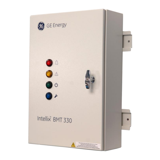
Intellix BMT 330 User Manual ™ APPENDIX 2 – FRONT PANEL LIGHTS Light Light Symbol Meaning Colour GREEN AC power applied BLUE Service Required. Triggered by warning service event. YELLOW A measured parameter has exceeded a user- programmed “warning” threshold. A measured parameter has exceeded a user- programmed “alarm”...