GE MiCOM P40 Agile Technical Manual
Hide thumbs
Also See for MiCOM P40 Agile:
- Technical manual (962 pages) ,
- Technical manual (458 pages) ,
- Technical manual (802 pages)
Table of Contents
Advertisement
Quick Links
Download this manual
See also:
Technical Manual
Advertisement
Table of Contents
Troubleshooting

Related Manuals for GE MiCOM P40 Agile


Summary of Contents for GE MiCOM P40 Agile
- Page 1 GE Energy Connections Grid Solutions MiCOM P40 Agile P14D Technical Manual Feeder Management IED Hardware Version: A Software Version: 60 Publication Reference: P14D-TM-EN-8...
-
Page 3: Table Of Contents
Contents Chapter 1 Introduction Chapter Overview Foreword Target Audience Typographical Conventions Nomenclature Compliance Product Scope Ordering Options Features and Functions Protection Functions Control Functions Measurement Functions Communication Functions Logic Diagrams Functional Overview Chapter 2 Safety Information Chapter Overview Health and Safety Symbols Installation, Commissioning and Servicing Lifting Hazards... - Page 4 Contents P14D 30TE Front Panel Keypad Liquid Crystal Display USB Port Fixed Function LEDs Function Keys Programable LEDs Chapter 4 Software Design Chapter Overview Software Design Overview System Level Software Real Time Operating System System Services Software Self-Diagnostic Software Startup Self-Testing 3.4.1 System Boot 3.4.2...
- Page 5 P14D Contents Chapter 6 Current Protection Functions Chapter Overview Overcurrent Protection Principles IDMT Characteristics 2.1.1 IEC 60255 IDMT Curves 2.1.2 European Standards 2.1.3 North American Standards 2.1.4 IEC and IEEE Inverse Curves 2.1.5 Differences Between the North american and European Standards 2.1.6 Programmable Curves Principles of Implementation...
- Page 6 Contents P14D 8.4.2 Icos phi / Isin phi characteristic 8.4.3 Directional SEF Logic Application Notes 8.5.1 Insulated Systems 8.5.2 Setting Guidelines (Insulated Systems) Cold Load Pickup Implementation CLP Logic Application Notes 9.3.1 CLP for Resistive Loads 9.3.2 CLP for Motor Feeders 9.3.3 CLP for Switch Onto Fault Conditions Selective Logic...
- Page 7 P14D Contents Chapter Overview REF Protection Principles Resistance-Earthed Star Windings Solidly-Earthed Star Windings Through Fault Stability Restricted Earth Fault Types 2.4.1 Low Impedance REF Principle 2.4.2 High Impedance REF Principle Restricted Earth Fault Protection Implementation Restricted Earth Fault Protection Implementation Low Impedance REF 3.2.1 Setting the Bias Characteristic...
- Page 8 Contents P14D 2.4.1 Directional Elements 2.4.2 Non-directional Elements Low Impedance REF Protection High Impedance REF Protection High Impedance Busbar Protection Use of Metrosil Non-linear Resistors Use of ANSI C-class CTs Chapter 10 Voltage Protection Functions Chapter Overview Undervoltage Protection Undervoltage Protection Implementation Undervoltage Protection Logic Application Notes 2.3.1...
- Page 9 P14D Contents Frequency Protection Overview Frequency Protection Implementation Underfrequency Protection Underfrequency Protection Implementation Underfrequency Protection Logic Application Notes 3.3.1 Setting Guidelines Overfrequency Protection Overfrequency Protection Implementation Overfrequency Protection Logic Application Notes 4.3.1 Setting Guidelines Independent R.O.C.O.F Protection Indepenent R.O.C.O.F Protection Implementation Independent R.O.C.O.F Protection Logic Application Notes 5.3.1...
- Page 10 Contents P14D 4.4.2 Sensitive Power Setting Guidelines Wattmetric Directional Earth Fault Protection WDE Implementation WDE Logic Chapter 13 Autoreclose Chapter Overview Introduction to 3-phase Autoreclose Implementation Autoreclose Function Inputs CB Healthy Block AR Reset Lockout AR Auto Mode AR LiveLine Mode Telecontrol Mode Live/Dead Ccts OK (Live/Dead Circuits OK) AR Sys Checks (AR System Checks)
- Page 11 P14D Contents 7.2.2 Trip Signal Logic 7.2.3 Blocking Signal Logic 7.2.4 Shots Exceeded Logic 7.2.5 AR Initiation Logic Blocking Instantaneous Protection for Selected Trips Blocking Instantaneous Protection for Lockouts Dead Time Control 7.5.1 AR CB Close Control AR System Checks Reclaim Timer Initiation Autoreclose Inhibit Autoreclose Lockout...
- Page 12 Contents P14D CB State Monitoring Logic Circuit Breaker Control CB Control using the IED Menu CB Control using the Hotkeys CB Control using the Function Keys CB Control using the Opto-inputs Remote CB Control Synchronisation Check CB Healthy Check CB Control Logic Pole Dead Function Pole Dead Logic System Checks...
- Page 13 P14D Contents 5.3.2 PSL for TCS Scheme 3 Trip Circuit Supervision Scheme 4 5.4.1 Resistor Values 5.4.2 PSL for TCS Scheme 4 Chapter 16 Digital I/O and PSL Configuration Chapter Overview Configuring Digital Inputs and Outputs Scheme Logic PSL Editor PSL Schemes PSL Scheme Version Control Configuring the Opto-Inputs...
- Page 14 Contents P14D 6.2.6 Cyclic Measurements 6.2.7 Commands 6.2.8 Test Mode 6.2.9 Disturbance Records 6.2.10 Command/Monitor Blocking 6.2.11 IEC 60870-5-103 Configuration DNP 3.0 6.3.1 Physical Connection and Link Layer 6.3.2 Object 1 Binary Inputs 6.3.3 Object 10 Binary Outputs 6.3.4 Object 20 Binary Counters 6.3.5 Object 30 Analogue Input 6.3.6...
- Page 15 P14D Contents NERC Compliance 3.1.1 CIP 002 3.1.2 CIP 003 3.1.3 CIP 004 3.1.4 CIP 005 3.1.5 CIP 006 3.1.6 CIP 007 3.1.7 CIP 008 3.1.8 CIP 009 IEEE 1686-2007 Cyber-Security Implementation NERC-Compliant Display Four-level Access 4.2.1 Blank Passwords 4.2.2 Password Rules 4.2.3 Access Level DDBs...
- Page 16 Contents P14D Chapter 20 Commissioning Instructions Chapter Overview General Guidelines Commissioning Test Menu Opto I/P Status Cell (Opto-input Status) Relay O/P Status Cell (Relay Output Status) Test Port Status Cell Monitor Bit 1 to 8 Cells Test Mode Cell Test Pattern Cell Contact Test Cell Test LEDs Cell Test Autoreclose Cell...
- Page 17 P14D Contents Chapter Overview Maintenance Maintenance Checks 2.1.1 Alarms 2.1.2 Opto-isolators 2.1.3 Output Relays 2.1.4 Measurement Accuracy Replacing the Unit Cleaning Troubleshooting Self-Diagnostic Software Power-up Errors Error Message or Code on Power-up Out of Service LED on at Power-up Error Code during Operation Mal-operation during testing 3.6.1 Failure of Output Contacts...
- Page 18 Contents P14D Negative Sequence Voltage Protection Rate of Change of Voltage Protection Performance of Frequency Protection Functions Overfrequency Protection Underfrequency Protection Supervised Rate of Change of Frequency Protection Independent Rate of Change of Frequency Protection Average Rate of Change of Frequency Protection Load Restoration Power Protection Functions Overpower / Underpower Protection...
- Page 19 P14D Contents 15.1 Insulation 15.2 Creepage Distances and Clearances 15.3 High Voltage (Dielectric) Withstand 15.4 Impulse Voltage Withstand Test Electromagnetic Compatibility 16.1 1 MHz Burst High Frequency Disturbance Test 16.2 Damped Oscillatory Test 16.3 Immunity to Electrostatic Discharge 16.4 Electrical Fast Transient or Burst Requirements 16.5 Surge Withstand Capability 16.6...
- Page 20 Contents P14D xviii P14D-TM-EN-8...
- Page 21 Table of Figures Figure 1: Key to logic diagrams Figure 2: Functional Overview Figure 3: Hardware design overview Figure 4: Exploded view of IED Figure 5: 20TE rear panel Figure 6: 30TE Three-MIDOS block rear panel Figure 7: 30TE Two-MIDOS block + communications rear panel Figure 8: 30TE Two-MIDOS block + blanking plate Figure 9:...
- Page 22 Table of Figures P14D Figure 39: Distribution of currents during a Phase C fault Figure 40: Phasors for a phase C earth fault in a Petersen Coil earthed system Figure 41: Zero sequence network showing residual currents Figure 42: Phase C earth fault in Petersen Coil earthed system: practical case with resistance present Figure 43: Non-directional SEF logic...
- Page 23 P14D Table of Figures Figure 78: High Impedance REF Connection Figure 79: REF bias characteristic Figure 80: Star winding, resistance earthed Figure 81: Percentage of winding protected Figure 82: Low Impedance REF Scaling Factor Figure 83: Hi-Z REF protection for a grounded star winding Figure 84: Hi-Z REF protection for a delta winding Figure 85:...
- Page 24 Table of Figures P14D Figure 118: Transient voltage vector change q due to change in load current IDL Figure 119: Underfrequency logic (single stage) Figure 120: Overfrequency logic (single stage) Figure 121: Power system segregation based upon frequency measurements Figure 122: Independent rate of change of frequency logic (single stage) Figure 123: Frequency-supervised rate of change of frequency logic (single stage)
- Page 25 P14D Table of Figures Figure 158: Check Synchronisation vector diagram Figure 159: System Check logic Figure 160: System Check PSL Figure 161: Representation of typical feeder bay Figure 162: Switch Status logic Figure 163: Switch Control logic Figure 164: DC Supply Monitor zones Figure 165: DC Supply Monitor logic Figure 166:...
- Page 26 Table of Figures P14D Figure 198: MiDOS terminal block Figure 199: Earth link for cable screen Figure 200: 20TE case dimensions Figure 201: 30TE case dimensions Figure 202: RP1 physical connection Figure 203: Remote communication using K-bus xxiv P14D-TM-EN-8...
-
Page 27: Chapter 1 Introduction
CHAPTER 1 INTRODUCTION... -
Page 28: Rear Serial Port
Chapter 1 - Introduction P14D P14D-TM-EN-8... -
Page 29: Chapter Overview
P14D Chapter 1 - Introduction CHAPTER OVERVIEW This chapter provides some general information about the technical manual and an introduction to the device(s) described in this technical manual. This chapter contains the following sections: Chapter Overview Foreword Product Scope Features and Functions Logic Diagrams Functional Overview P14D-TM-EN-8... -
Page 30: Foreword
Chapter 1 - Introduction P14D FOREWORD This technical manual provides a functional and technical description of General Electric's P14D, as well as a comprehensive set of instructions for using the device. The level at which this manual is written assumes that you are already familiar with protection engineering and have experience in this discipline. -
Page 31: Nomenclature
P14D Chapter 1 - Introduction NOMENCLATURE Due to the technical nature of this manual, many special terms, abbreviations and acronyms are used throughout the manual. Some of these terms are well-known industry-specific terms while others may be special product- specific terms used by General Electric. The first instance of any acronym or term used in a particular chapter is explained. -
Page 32: Product Scope
Chapter 1 - Introduction P14D PRODUCT SCOPE The P14D feeder management IED has been designed for the protection of a wide range of overhead lines and underground cables. The P14D provides integral directional and non-directional overcurrent, overvoltage and earth-fault protection and is suitable for application on solidly earthed, impedance earthed, Petersen coil earthed, and isolated systems. -
Page 33: Features And Functions
P14D Chapter 1 - Introduction FEATURES AND FUNCTIONS PROTECTION FUNCTIONS The P14D models offer the following protection functions: ANSI IEC 61850 Protection Function P14DA P14DB P14DG P14DH P14DL P14DZ Undercurrent detection (low load) NgcPTOC Negative sequence overcurrent 46BC Broken Conductor ThmPTTR Thermal Overload 50 SOTF... -
Page 34: Control Functions
Chapter 1 - Introduction P14D ANSI IEC 61850 Protection Function P14DA P14DB P14DG P14DH P14DL P14DZ Check synchronising Phase Directional Power Sensitive power Load Encroachment supervision (Load Blinders) RREC Autoreclose (3 phases) 4 shots 4 shots 21FL Fault Locator Frequency supervised rate of change 81RF DfpPFRC of frequency... -
Page 35: Measurement Functions
P14D Chapter 1 - Introduction MEASUREMENT FUNCTIONS The device offers the following measurement functions: Measurement Function Details Measurements Measured currents and calculated sequence ● and RMS currents (Exact range of measurements depend on the device model) Measured voltages and calculated sequence ●... -
Page 36: Logic Diagrams
Chapter 1 - Introduction P14D LOGIC DIAGRAMS This technical manual contains many logic diagrams, which should help to explain the functionality of the device. Although this manual has been designed to be as specific as possible to the chosen product, it may contain diagrams, which have elements applicable to other products. -
Page 37: Functional Overview
P14D Chapter 1 - Introduction FUNCTIONAL OVERVIEW 50BF 46BC SOTF 81RF 21FL 81RAV 81df/dt Digital I/O Communication Measurements Disturbance Opto- Relay Local records IRIG-B Ethernet RS485 Fault records inputs outputs V00001 Figure 2: Functional Overview P14D-TM-EN-8... - Page 38 Chapter 1 - Introduction P14D P14D-TM-EN-8...
-
Page 39: Chapter 2 Safety Information
CHAPTER 2 SAFETY INFORMATION... - Page 40 Chapter 2 - Safety Information P14D P14D-TM-EN-8...
-
Page 41: Chapter Overview
P14D Chapter 2 - Safety Information CHAPTER OVERVIEW This chapter provides information about the safe handling of the equipment. The equipment must be properly installed and handled in order to maintain it in a safe condition and to keep personnel safe at all times. You must be familiar with information contained in this chapter before unpacking, installing, commissioning, or servicing the equipment. -
Page 42: Health And Safety
Chapter 2 - Safety Information P14D HEALTH AND SAFETY Personnel associated with the equipment must be familiar with the contents of this Safety Information. When electrical equipment is in operation, dangerous voltages are present in certain parts of the equipment. Improper use of the equipment and failure to observe warning notices will endanger personnel. -
Page 43: Symbols
P14D Chapter 2 - Safety Information SYMBOLS Throughout this manual you will come across the following symbols. You will also see these symbols on parts of the equipment. Caution: Refer to equipment documentation. Failure to do so could result in damage to the equipment Warning: Risk of electric shock... -
Page 44: Installation, Commissioning And Servicing
Chapter 2 - Safety Information P14D INSTALLATION, COMMISSIONING AND SERVICING LIFTING HAZARDS Many injuries are caused by: Lifting heavy objects ● Lifting things incorrectly ● ● Pushing or pulling heavy objects Using the same muscles repetitively ● Plan carefully, identify any possible hazards and determine how best to move the product. Look at other ways of moving the load to avoid manual handling. -
Page 45: Ul/Csa/Cul Requirements
P14D Chapter 2 - Safety Information Caution: NEVER look into optical fibres or optical output connections. Always use optical power meters to determine operation or signal level. Warning: Testing may leave capacitors charged to dangerous voltage levels. Discharge capacitors by rediucing test voltages to zero before disconnecting test leads. Caution: Operate the equipment within the specified electrical and environmental limits. -
Page 46: Equipment Connections
Chapter 2 - Safety Information P14D Caution: Digital input circuits should be protected by a high rupture capacity NIT or TIA fuse with maximum rating of 16 A. for safety reasons, current transformer circuits must never be fused. Other circuits should be appropriately fused to protect the wire used. Caution: CTs must NOT be fused since open circuiting them may produce lethal hazardous voltages... -
Page 47: Pre-Energisation Checklist
P14D Chapter 2 - Safety Information Caution: Use a locknut or similar mechanism to ensure the integrity of stud-connected PCTs. Caution: The recommended minimum PCT wire size is 2.5 mm² for countries whose mains supply is 230 V (e.g. Europe) and 3.3 mm² for countries whose mains supply is 110 V (e.g. North America). -
Page 48: Upgrading/Servicing
Chapter 2 - Safety Information P14D Note: For most Alstom equipment with ring-terminal connections, the threaded terminal block for current transformer termination is automatically shorted if the module is removed. Therefore external shorting of the CTs may not be required. Check the equipment documentation and wiring diagrams first to see if this applies. -
Page 49: Decommissioning And Disposal
P14D Chapter 2 - Safety Information DECOMMISSIONING AND DISPOSAL Caution: Before decommissioning, completely isolate the equipment power supplies (both poles of any dc supply). The auxiliary supply input may have capacitors in parallel, which may still be charged. To avoid electric shock, discharge the capacitors using the external terminals before decommissioning. -
Page 50: Regulatory Compliance
Chapter 2 - Safety Information P14D REGULATORY COMPLIANCE Compliance with the European Commission Directive on EMC and LVD is demonstrated using a technical file. EMC COMPLIANCE: 2014/30/EU The product specific Declaration of Conformity (DoC) lists the relevant harmonised standard(s) or conformit assessment used to demonstrate compliance with the EMC directive. - Page 51 P14D Chapter 2 - Safety Information Where: 'II' Equipment Group: Industrial. '(2)G' High protection equipment category, for control of equipment in gas atmospheres in Zone 1 and 2. This equipment (with parentheses marking around the zone number) is not itself suitable for operation within a potentially explosive atmosphere.
- Page 52 Chapter 2 - Safety Information P14D P14D-TM-EN-8...
-
Page 53: Chapter 3 Hardware Design
CHAPTER 3 HARDWARE DESIGN... - Page 54 Chapter 3 - Hardware Design P14D P14D-TM-EN-8...
-
Page 55: Chapter Overview
P14D Chapter 3 - Hardware Design CHAPTER OVERVIEW This chapter provides information about the product's hardware design. This chapter contains the following sections: Chapter Overview Hardware Architecture Mechanical Implementation Terminal Connections Front Panel P14D-TM-EN-8... -
Page 56: Hardware Architecture
Chapter 3 - Hardware Design P14D HARDWARE ARCHITECTURE The main components comprising devices based on the P40Agile platform are as follows: The housing, consisting of a front panel and connections at the rear ● The Main processor module consisting of the main CPU (Central Processing Unit), memory and an interface ●... -
Page 57: Mechanical Implementation
P14D Chapter 3 - Hardware Design MECHANICAL IMPLEMENTATION All products based on the P40Agile platform have common hardware architecture. The hardware comprises two main parts; the cradle and the housing. The cradle consists of the front panel which is attached to a carrier board into which all of the hardware boards and modules are connected. -
Page 58: 20Te Rear Panel
Chapter 3 - Hardware Design P14D Case width (TE) Case width (mm) Equivalent K series 20TE 102.4 mm (4 inches) KCGG140/142 30TE 154.2 mm (6 inches) KCEG140/142 20TE REAR PANEL The 20TE rear panel consists of two MIDOS heavy duty terminal blocks. Figure 5: 20TE rear panel 30TE REAR PANEL The 30TE rear panel consists of either:... -
Page 59: Figure 6: 30Te Three-Midos Block Rear Panel
P14D Chapter 3 - Hardware Design Figure 6: 30TE Three-MIDOS block rear panel Figure 7: 30TE Two-MIDOS block + communications rear panel P14D-TM-EN-8... -
Page 60: Figure 8: 30Te Two-Midos Block + Blanking Plate
Chapter 3 - Hardware Design P14D Figure 8: 30TE Two-MIDOS block + blanking plate P14D-TM-EN-8... -
Page 61: Terminal Connections
P14D Chapter 3 - Hardware Design TERMINAL CONNECTIONS I/O OPTIONS Component I/O option A I/O option B I/O option C I/O option D I/O option E I/O option F (1 group of 3 (2 groups of 3 (1 group of 3, 1 (1 group of 3 (1 group of 3) (1 group of 3... -
Page 62: Front Panel
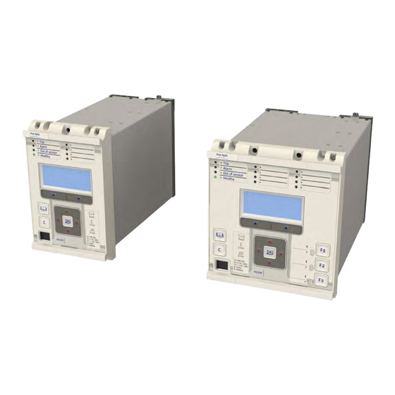
Chapter 3 - Hardware Design P14D FRONT PANEL 20TE FRONT PANEL Figure 9: Front panel (20TE) The figures show the front panels for the 20TE variant. It consists of: LCD display ● Keypad ● ● USB port 4 x fixed function tri-colour LEDs ●... -
Page 63: 30Te Front Panel
P14D Chapter 3 - Hardware Design 30TE FRONT PANEL Figure 10: Front panel (30TE) The figures show the front panels for the 30TE variant. It consists of: LCD display ● Keypad ● ● USB port 4 x fixed function tri-colour LEDs ●... -
Page 64: Liquid Crystal Display
Chapter 3 - Hardware Design P14D A clear key for clearing the last command A read key for viewing larger blocks of text (arrow keys now used for scrolling) 2 hot keys for scrolling through the default display and for control of setting groups. -
Page 65: Fixed Function Leds
P14D Chapter 3 - Hardware Design FIXED FUNCTION LEDS Four fixed-function LEDs on the left-hand side of the front panel indicate the following conditions. Trip (Red) switches ON when the IED issues a trip signal. It is reset when the associated fault record is ●... - Page 66 Chapter 3 - Hardware Design P14D P14D-TM-EN-8...
-
Page 67: Chapter 4 Software Design
CHAPTER 4 SOFTWARE DESIGN... - Page 68 Chapter 4 - Software Design P14D P14D-TM-EN-8...
-
Page 69: Chapter Overview
P14D Chapter 4 - Software Design CHAPTER OVERVIEW This chapter describes the software design of the IED. This chapter contains the following sections: Chapter Overview Software Design Overview System Level Software Platform Software Protection and Control Functions P14D-TM-EN-8... -
Page 70: Software Design Overview
Chapter 4 - Software Design P14D SOFTWARE DESIGN OVERVIEW The range of products based on the P40 Agile platform can be conceptually categorised into several elements as follows: The system level software ● The platform software ● The protection and control software ●... -
Page 71: System Level Software
P14D Chapter 4 - Software Design SYSTEM LEVEL SOFTWARE REAL TIME OPERATING SYSTEM The real-time operating system is used to schedule the processing of the various tasks. This ensures that they are processed in the time available and in the desired order of priority. The operating system also plays a part in controlling the communication between the software tasks. -
Page 72: System Level Software Initialisation
Chapter 4 - Software Design P14D 3.4.2 SYSTEM LEVEL SOFTWARE INITIALISATION The initialization process initializes the processor registers and interrupts, starts the watchdog timers (used by the hardware to determine whether the software is still running), starts the real-time operating system and creates and starts the supervisor task. -
Page 73: Platform Software
P14D Chapter 4 - Software Design PLATFORM SOFTWARE The platform software has three main functions: To control the logging of records generated by the protection software, including alarms, events, faults, and ● maintenance records To store and maintain a database of all of the settings in non-volatile memory ●... -
Page 74: Protection And Control Functions
Chapter 4 - Software Design P14D PROTECTION AND CONTROL FUNCTIONS The protection and control software processes all of the protection elements and measurement functions. To achieve this it has to communicate with the system services software, the platform software as well as organise its own operations. -
Page 75: Programmable Scheme Logic
P14D Chapter 4 - Software Design ´ (fundamental frequency)/2 (samples per cycle) At 24 samples per cycle, this would be nominally 600 Hz for a 50 Hz system, or 720 Hz for a 60 Hz system. The following figure shows the nominal frequency response of the anti-alias filter and the Fourier filter for a 24- sample single cycle fourier algorithm acting on the fundamental component: Ideal anti-alias filter response Fourier response without... -
Page 76: Disturbance Recorder
Chapter 4 - Software Design P14D may be triggered by a fatal error in the relay in which case it may not be possible to successfully store a maintenance record, depending on the nature of the problem. For more information, see the Monitoring and Control chapter. DISTURBANCE RECORDER The disturbance recorder operates as a separate task from the protection and control task. -
Page 77: Chapter 5 Configuration
CHAPTER 5 CONFIGURATION... - Page 78 Chapter 5 - Configuration P14D P14D-TM-EN-8...
-
Page 79: Chapter Overview
P14D Chapter 5 - Configuration CHAPTER OVERVIEW Each product has different configuration parameters according to the functions it has been designed to perform. There is, however, a common methodology used across the entire product series to set these parameters. Some of the communications setup can only be carried out using the HMI, and cannot be carried out using settings applications software. -
Page 80: Settings Application Software
Chapter 5 - Configuration P14D SETTINGS APPLICATION SOFTWARE To configure this device you will need to use the Settings Application Software. The settings application software used in this range of IEDs is called MiCOM S1 Agile. It is a collection of software tools, which is used for setting up and managing the IEDs. -
Page 81: Using The Hmi Panel
P14D Chapter 5 - Configuration USING THE HMI PANEL Using the HMI, you can: Display and modify settings ● View the digital I/O signal status ● ● Display measurements Display fault records ● Reset fault and alarm indications ● The keypad provides full access to the device functionality using a range of menu options. The information is displayed on the LCD. -
Page 82: Navigating The Hmi Panel
Chapter 5 - Configuration P14D Note: As the LCD display has a resolution of 16 characters by 3 lines, some of the information is in a condensed mnemonic form. NAVIGATING THE HMI PANEL The cursor keys are used to navigate the menus. These keys have an auto-repeat function if held down continuously. -
Page 83: Default Display
P14D Chapter 5 - Configuration Even though the device itself should be in full working order when you first start it, an alarm could still be present, for example, if there is no network connection for a device fitted with a network card. If this is the case, you can read the alarm by pressing the 'Read' key. -
Page 84: Default Display Navigation
Chapter 5 - Configuration P14D Access Level For example: Access Level HOTKEY In addition to the above, there are also displays for the system voltages, currents, power and frequency etc., depending on the device model. DEFAULT DISPLAY NAVIGATION The following diagram is an example of the default display navigation. In this example, we have used a cyber- secure model. -
Page 85: Password Entry
P14D Chapter 5 - Configuration Note: Whenever the IED has an uncleared alarm the default display is replaced by the text Alarms/ Faults present. You cannot override this default display. However, you can enter the menu structure from the default display, even if the display shows the Alarms/Faults present message. -
Page 86: Menu Structure
Chapter 5 - Configuration P14D Press Clear To Reset Alarms To clear all alarm messages, press the Clear key. To return to the display showing alarms or faults present, and leave the alarms uncleared, press the Read key. Depending on the password configuration settings, you may need to enter a password before the alarm messages can be cleared. -
Page 87: Changing The Settings
P14D Chapter 5 - Configuration Setting Column Description Sys Fn Links (Row 03) Third setting within first column … … … VIEW RECORDS Second Column definition Select Event [0...n] First setting within second column Menu Cell Ref Second setting within second column Time &... -
Page 88: Direct Access (The Hotkey Menu)
Chapter 5 - Configuration P14D Note: For the protection group and disturbance recorder settings, if the menu time-out occurs before the changes have been confirmed, the setting values are discarded. Control and support settings, howeverr, are updated immediately after they are entered, without the Update settings? prompt. -
Page 89: Circuit Breaker Control
P14D Chapter 5 - Configuration To access the hotkey menu from the default display, you press the key directly below the HOTKEY text on the LCD. The following screen will appear. ¬User32 STG GP® HOTKEY MENU EXIT Press the right cursor key twice to get to the first control input, or the left cursor key to get to the last control input. ¬STP GP User02®... - Page 90 Chapter 5 - Configuration P14D The first cell down in the FUNCTION KEYS column is the Fn Key Status cell. This contains a binary string, which represents the function key commands. Their status can be read from this binary string. FUNCTION KEYS Fn Key Status 0000000000...
-
Page 91: Date And Time Configuration
P14D Chapter 5 - Configuration DATE AND TIME CONFIGURATION The date and time setting will normally be updated automatically by the chosen UTC (Universal Time Co- ordination) time synchronisation mechanism when the device is in service. You can also set the date and time manually using the Date/Time cell in the DATE AND TIME column. -
Page 92: Settings Group Selection
Chapter 5 - Configuration P14D SETTINGS GROUP SELECTION You can select the setting group using opto inputs, a menu selection, and for some models the hotkey menu or function keys. You choose which method using the Setting Group setting in the CONFIGURATION column. There are two possibilities;... -
Page 93: Chapter 6 Current Protection Functions
CHAPTER 6 CURRENT PROTECTION FUNCTIONS... - Page 94 Chapter 6 - Current Protection Functions P14D P14D-TM-EN-8...
-
Page 95: Chapter Overview
P14D Chapter 6 - Current Protection Functions CHAPTER OVERVIEW The P14D provides a wide range of current protection functions. This chapter describes the operation of these functions including the principles, logic diagrams and applications. This chapter contains the following sections: Chapter Overview Overcurrent Protection Principles Phase Overcurrent Protection... -
Page 96: Overcurrent Protection Principles
Chapter 6 - Current Protection Functions P14D OVERCURRENT PROTECTION PRINCIPLES Most electrical power system faults result in an overcurrent of one kind or another. It is the job of protection devices, formerly known as 'relays' but now known as Intelligent Electronic Devices (IEDs) to protect the power system from faults. -
Page 97: Iec 60255 Idmt Curves
P14D Chapter 6 - Current Protection Functions 2.1.1 IEC 60255 IDMT CURVES There are four well-known variants of this characteristic: Standard Inverse ● Very inverse ● Extremely inverse ● UK Long Time inverse ● These equations and corresponding curves governing these characteristics are very well known in the power industry. - Page 98 Chapter 6 - Current Protection Functions P14D For cases where the generation is practically constant and discrimination with low tripping times is difficult to obtain, because of the low impedance per line section, an extremely inverse relay can be very useful since only a small difference of current is necessary to obtain an adequate time difference.
-
Page 99: European Standards
P14D Chapter 6 - Current Protection Functions 1000.00 100.00 Long Time Inverse ( 10.00 Standard Inverse (SI) 1.00 Very Inverse (VI) Extremely Inverse (EI) 0.10 Current (multiples of I E00600 Figure 15: IEC 60255 IDMT curves 2.1.2 EUROPEAN STANDARDS The IEC 60255 IDMT Operate equation is: β... -
Page 100: North American Standards
Chapter 6 - Current Protection Functions P14D b constant a constant Curve Description L constant IEC Very Inverse Operate 13.5 IEC Very Inverse Reset 50.92 IEC Extremely Inverse Operate IEC Extremely Inverse Reset 44.1 3.03 UK Long Time Inverse Operate* BPN (EDF) Operate* 1000 0.655... - Page 101 P14D Chapter 6 - Current Protection Functions The constant values for the IEEE curves are as follows: b constant a constant Curve Description L constant IEEE Moderately Inverse Operate 0.0515 0.02 0.114 IEEE Moderately Inverse Reset 4.85 IEEE Very Inverse Operate 19.61 0.491 IEEE Very Inverse Reset...
-
Page 102: Iec And Ieee Inverse Curves
Chapter 6 - Current Protection Functions P14D 2.1.4 IEC AND IEEE INVERSE CURVES IEC Standard Inverse Curve IEC Very Inverse Curve 1000 1000 0.025 0.025 0.075 0.075 0.100 0.100 0.300 0.300 0.500 0.500 0.700 0.700 0.900 0.900 1.000 1.000 1.200 1.200 0.01 0.01... -
Page 103: Differences Between The North American And European Standards
P14D Chapter 6 - Current Protection Functions IEEE Very Inverse Curve IEEE Extremely Inverse Curve 10000 10000 0.05 0.05 1000 1000 0.01 0.01 Current in Multiples of Setting Current in Multiples of Setting E00759 Figure 18: IEEE very and extremely inverse curves 2.1.5 DIFFERENCES BETWEEN THE NORTH AMERICAN AND EUROPEAN STANDARDS The IEEE and US curves are set differently to the IEC/UK curves, with regard to the time setting. -
Page 104: Timer Hold Facility
Chapter 6 - Current Protection Functions P14D Energising quantity Start signal IDMT/ DT Threshold & & & Trip Signal Function inhibit Stage Blocking signals Timer Settings Stage Blocking settings Voltage Directional Check Current Timer Blocking signals Timer Blocking settings V00654 Figure 19: Principle of protection function implementation An energising quantity is either a voltage input from a system voltage transformer, a current input from a system current transformer or another quantity derived from one or both of these. - Page 105 P14D Chapter 6 - Current Protection Functions similar way to an electromechanical relay. If you set the hold timer to zero, the overcurrent timer for that stage will reset instantaneously as soon as the current falls below a specified percentage of the current setting (typically 95%).
-
Page 106: Phase Overcurrent Protection
Chapter 6 - Current Protection Functions P14D PHASE OVERCURRENT PROTECTION Phase current faults are faults where fault current flows between two or more phases of a power system. The fault current may be between the phase conductors only or, between two or more phase conductors and earth. Although not as common as earth faults (single phase to earth), phase faults are typically more severe. -
Page 107: Non-Directional Overcurrent Logic
P14D Chapter 6 - Current Protection Functions NON-DIRECTIONAL OVERCURRENT LOGIC I>1 Start A & I>1 Current Set & I>1 Trip A IDMT/DT IA 2H Start & Timer Settings I> Blocking 2H Blocks I>1 2H 1PH Block I>1 Start B & I>1 Current Set &... -
Page 108: Directional Element
Chapter 6 - Current Protection Functions P14D DIRECTIONAL ELEMENT If fault current can flow in both directions through a protected location, you will need to use a directional overcurrent element to determine the direction of the fault. Once the direction has been determined the device can decide whether to allow tripping or to block tripping. -
Page 109: Figure 21: Directional Trip Angles
P14D Chapter 6 - Current Protection Functions V00747 Figure 21: Directional trip angles For close up three-phase faults, all three voltages will collapse to zero and no healthy phase voltages will be present. For this reason, the device includes a synchronous polarisation feature that stores the pre-fault voltage information and continues to apply this to the directional overcurrent elements for a time period of a few seconds. -
Page 110: Directional Overcurrent Logic
Chapter 6 - Current Protection Functions P14D 3.3.1 DIRECTIONAL OVERCURRENT LOGIC I>1 Start A & I>1 Current Set & I>1 Trip A IDMT/DT & IA 2H Start & I> Blocking 2H Block I>1 Timer Settings 2H 1PH BLOCK I2H Any Start &... -
Page 111: Application Notes
P14D Chapter 6 - Current Protection Functions APPLICATION NOTES 3.5.1 PARALLEL FEEDERS 33 kV OC/EF OC/EF SBEF DOC/DEF DOC/DEF OC/EF OC/EF 11 kV OC/EF Loads E00603 Figure 23: Typical distribution system using parallel transformers In the application shown in the diagram, a fault at ‘F’ could result in the operation of both R3 and R4 resulting in the loss of supply to the 11 kV busbar. -
Page 112: Ring Main Arrangements
Chapter 6 - Current Protection Functions P14D 3.5.2 RING MAIN ARRANGEMENTS Source 2.1s 2.1s 0.1s 0.1s Load Load 1.7s Load 1.7s Load 0.5s 0.5s Load 1.3s 1.3s Load 0.9s 0.9s E00604 Figure 24: Typical ring main with associated overcurrent protection In a ring main arrangement, current may flow in either direction through the various device locations, therefore directional overcurrent devices are needed to achieve correct discrimination. -
Page 113: Setting Guidelines (Directional Element)
P14D Chapter 6 - Current Protection Functions This example is for a device feeding a LV switchboard and makes the following assumptions: CT Ratio = 500/1 ● ● Full load current of circuit = 450A Slowest downstream protection = 100A Fuse ●... -
Page 114: Voltage Dependent Overcurrent Element
Chapter 6 - Current Protection Functions P14D VOLTAGE DEPENDENT OVERCURRENT ELEMENT An overcurrent protection scheme is co-ordinated throughout a system such that cascaded operation is achieved. This means that if for some reason a downstream circuit breaker fails to trip for a fault condition, the next upstream circuit breaker should trip. -
Page 115: Voltage Restrained Overcurrent Protection
P14D Chapter 6 - Current Protection Functions 4.1.2 VOLTAGE RESTRAINED OVERCURRENT PROTECTION In Voltage Restrained Operation (VRO) mode the effective operating current of the protection element is continuously variable as the applied voltage varies between two voltage thresholds. This protection mode is considered to be better suited to applications where the generator is connected to the system via a generator transformer. -
Page 116: Voltage Dependent Overcurrent Logic
Chapter 6 - Current Protection Functions P14D VOLTAGE DEPENDENT OVERCURRENT LOGIC V Dep OC Status VCO I>1 & VRO I>1 Vdep OC Start AB V Dep OC V<1 Set I>1 Current Set Applied Current × Threshold V Dep OC k Set &... - Page 117 P14D Chapter 6 - Current Protection Functions Example If the overcurrent device has a setting of 160% In, but the minimum fault current for the remote fault condition is only 80% In, then the required k factor is given by: 0 42 ×...
-
Page 118: Current Setting Threshold Selection
Chapter 6 - Current Protection Functions P14D CURRENT SETTING THRESHOLD SELECTION The Phase Overcurrent protection threshold setting can be influenced by the Cold Load Pickup (CLP)and the Voltage Dependent Overcurrent (V DepOC) functions, should this functionality be used. The Overcurrent function selects the threshold setting according to the following diagram: Start Use the threshold setting Does a Voltage Dependent... -
Page 119: Negative Sequence Overcurrent Protection
P14D Chapter 6 - Current Protection Functions NEGATIVE SEQUENCE OVERCURRENT PROTECTION When applying standard phase overcurrent protection, the overcurrent elements must be set significantly higher than the maximum load current. This limits the element’s sensitivity. Most protection schemes also use an earth fault element operating from residual current, which improves sensitivity for earth faults. -
Page 120: Non-Directional Negative Sequence Overcurrent Logic
Chapter 6 - Current Protection Functions P14D NON-DIRECTIONAL NEGATIVE SEQUENCE OVERCURRENT LOGIC I2>1 Start & I2>1 Current Set & I2>1 Trip IDMT/DT CTS Block Timer Settings I 2> Inhibit I2 H Any Start Note: This diagram does not show all stages . Other stages follow similar principles. -
Page 121: Application Notes
P14D Chapter 6 - Current Protection Functions should be set equal to the phase angle of the negative sequence current with respect to the inverted negative sequence voltage (–V2), in order to be at the centre of the directional characteristic. For the negative phase sequence directional elements to operate, the device must detect a polarising voltage above a minimum threshold, I2>... - Page 122 Chapter 6 - Current Protection Functions P14D For the negative phase sequence directional elements to operate, the device must detect a polarising voltage above a minimum threshold, I2> V2pol Set. This must be set in excess of any steady state negative phase sequence voltage.
-
Page 123: Earth Fault Protection
P14D Chapter 6 - Current Protection Functions EARTH FAULT PROTECTION Earth faults are overcurrent faults where the fault current flows to earth. Earth faults are the most common type of fault. Earth faults can be measured directly from the system by means of: ●... -
Page 124: Non-Directional Earth Fault Logic
Chapter 6 - Current Protection Functions P14D NON-DIRECTIONAL EARTH FAULT LOGIC IN2>1 Start & IN2>1 Current & IDMT/DT IN2>1 Trip CTS Block Timer Settings Not applicable for IN1 IN2> Inhibit Note: This diagram shows the logic for IN2 (derived earth fault ). The logic I2H Any Start for IN1 (measured earth fault ) follows the same principles, but with no CTS blocking. -
Page 125: Directional Element
P14D Chapter 6 - Current Protection Functions Note: Although the start point of the characteristic is defined by the "ΙN>" setting, the actual current threshold is a different setting called "IDG Ιs". The "IDG Ιs" setting is set as a multiple of "ΙN>". Note: When using an IDG Operate characteristic, DT is always used with a value of zero for the Rest characteristic. -
Page 126: Figure 33: Directional Angles
Chapter 6 - Current Protection Functions P14D Note: Residual voltage is nominally 180° out of phase with residual current. Consequently, the DEF elements are polarised from the "-Vres" quantity. This 180° phase shift is automatically introduced within the device. The directional criteria with residual voltage polarisation is given below: Directional forward (Ð... -
Page 127: Negative Sequence Polarisation
P14D Chapter 6 - Current Protection Functions 7.4.1.1 DIRECTIONAL EARTH FAULT LOGIC WITH RESIDUAL VOLTAGE POLARISATION IN1 > DIRECTIONAL IN1> VNpol Set Low Current Threshold Directional To EF logic check IN1>1 Char Angle IN1>1 Trip Angle VTS Slow Block Note: This diagram shows the logic for IN1 (measured earth fault ). The logic for IN2 (derived earth fault ) follows similar principles. -
Page 128: Application Notes
Chapter 6 - Current Protection Functions P14D V00749 Figure 35: Directional angles 7.4.2.1 DIRECTIONAL EARTH FAULT LOGIC WITH NPS POLARISATION IN1 > DIRECTIONAL IN1> V2 pol Set IN1> I2pol Set Directional To EF logic check IN1>1 Char Angle IN1>1 Trip Angle VTS Slow Block Note: This diagram shows the logic for IN 1 (measured earth fault ). -
Page 129: Peterson Coil Earthed Systems
P14D Chapter 6 - Current Protection Functions 7.5.2 PETERSON COIL EARTHED SYSTEMS A Petersen Coil earthing system is used in cases of high impedance earthing. Petersen Coil earthed systems (also called compensated or resonant systems) are commonly found in areas where the system consists mainly of rural overhead lines. -
Page 130: Figure 39: Distribution Of Currents During A Phase C Fault
Chapter 6 - Current Protection Functions P14D V00632 Figure 39: Distribution of currents during a Phase C fault Assuming that no resistance is present in X or X , the resulting phasor diagrams will be as shown in the figure below: = -3V = 3V... -
Page 131: Figure 41: Zero Sequence Network Showing Residual Currents
P14D Chapter 6 - Current Protection Functions The magnitude of the residual current I is equal to three times the steady-state charging current per phase. On the faulted feeder, the residual current is equal to I (C). This is shown in the zero sequence network shown in the following figure: Faulty feeder = Residual current on faulted feeder... -
Page 132: Setting Guidelines (Compensated Networks)
Chapter 6 - Current Protection Functions P14D Directionality is usually implemented using a Wattmetric function, or a transient earth fault detection function (TEFD), rather than a simple directional function, since they are more sensitive. 7.5.3 SETTING GUIDELINES (COMPENSATED NETWORKS) The directional setting should be such that the forward direction is looking down into the protected feeder (away from the busbar), with a 0°... -
Page 133: Sensitive Earth Fault Protection
P14D Chapter 6 - Current Protection Functions SENSITIVE EARTH FAULT PROTECTION With some earth faults, the fault current flowing to earth is limited by either intentional resistance (as is the case with some HV systems) or unintentional resistance (e.g. in very dry conditions and where the substrate is high resistance, such as sand or rock). -
Page 134: Epatr B Curve
Chapter 6 - Current Protection Functions P14D SEF protection can follow the same IDMT characteristics as described in the Overcurrent Protection Principles section. Please refer to this section for details of IDMT characteristics. EPATR B CURVE The EPATR B curve is commonly used for time-delayed Sensitive Earth Fault protection in certain markets. This curve is only available in the Sensitive Earth Fault protection stages 1 and 2. -
Page 135: Wattmetric Characteristic
P14D Chapter 6 - Current Protection Functions Unearthed Systems Compensated Systems Solidly Earthed Systems Resistance-Earthed Systems (insulated systems) (Petersen coil) Directional SEF Directional SEF Directional SEF Directional SEF Core-balanced INsin(j) INcos(j) INcos(j) characteristic characteristic characteristic Directional Core-balanced Wattmetric Wattmetric Earth Fault VN x IN sin (j) VN x IN cos (j) (reactive power) -
Page 136: Icos Phi / Isin Phi Characteristic
Chapter 6 - Current Protection Functions P14D The power setting is called PN> and is calculated using residual quantities. The formula for operation is as follows: The PN> setting corresponds to: f f f f cos( ) = 9V cos( where: f = Angle between the Polarising Voltage (-Vres) and the Residual Current... -
Page 137: Figure 47: Operating Characteristic For Icos
P14D Chapter 6 - Current Protection Functions Faulted Icos( 1) Feeder Polarising Voltage Forward Operation Icos( 2) Healthy Feeder Reverse Reverse Operation Operation E00618 Figure 47: Operating characteristic for Icos The diagram illustrates the method of discrimination when the real (cosf ) component is considered. Faults close to the polarising voltage will have a higher magnitude than those close to the operating boundary. -
Page 138: Directional Sef Logic
Chapter 6 - Current Protection Functions P14D 8.4.3 DIRECTIONAL SEF LOGIC SEF Options ISEF ISEFsin(phi) ISEF>1 Start ISEFcos(phi) & ISEF>1 Current & & ISEF>1 Trip IDMT/DT Inhibit SEF I2H Any Start Timer Settings ISEF> Blocking & 2 H Blocks ISEF>1 ISEF>1 Direction VN.ISEF.cos phi &... -
Page 139: Figure 49: Current Distribution In An Insulated System With C Phase Fault
P14D Chapter 6 - Current Protection Functions currents that occurs under earth fault conditions. A core balanced CT must be used for this application. This eliminates the possibility of spill current that may arise from slight mismatches between residually connected line CTs. -
Page 140: Setting Guidelines (Insulated Systems)
Chapter 6 - Current Protection Functions P14D Restrain Vapf Operate Vcpf Vbpf Vres (= 3Vo) An RCA setting of ±90º shifts the IR3 = (IH1 + IH2) “centre of the characteristic” to here E00628 Figure 50: Phasor diagrams for insulated system with C phase fault The current imbalance detected by a core balanced current transformer on the healthy feeders is the vector addition of Ia1 and Ib1. -
Page 141: Figure 51: Positioning Of Core Balance Current Transformers
P14D Chapter 6 - Current Protection Functions Cable gland Cable box Cable gland/shealth earth connection “Incorrect” No operation “Correct” Operation E00614 Figure 51: Positioning of core balance current transformers If the cable sheath is terminated at the cable gland and directly earthed at that point, a cable fault (from phase to sheath) will not result in any unbalanced current in the core balance CT. -
Page 142: Cold Load Pickup
Chapter 6 - Current Protection Functions P14D COLD LOAD PICKUP When a feeder circuit breaker is closed in order to energise a load, the current levels that flow for a period of time following energisation may be far greater than the normal load levels. Consequently, overcurrent settings that have been applied to provide overcurrent protection may not be suitable during this period of energisation (cold load), as they may initiate undesired tripping of the circuit breaker. -
Page 143: Application Notes
P14D Chapter 6 - Current Protection Functions The CLP Operation signal indicates that CLP logic is in operation. This only happens when CLP is enabled AND CLP is initiated either externally or from a CB Open condition after the tcold period has elapsed. The CLP Operation indicator goes low when CLP is disabled or when the external CLP trigger is removed or when there is a CB closed condition. -
Page 144: Selective Logic
Chapter 6 - Current Protection Functions P14D SELECTIVE LOGIC With Selective Logic you can use the Start signals to control the time delays of upstream IEDs, as an alternative to simply blocking them. This provides an alternative approach to achieving non-cascading types of overcurrent scheme. - Page 145 P14D Chapter 6 - Current Protection Functions Note: The Auto-reclose function outputs two signals that block protection, namely; AR Blk Main Prot and AR Blk SEF Prot. AR Blk Main Prot is common to Phase Overcurrent, Earth Fault 1 and Earth Fault 2, whereas AR Blk SEF Prot is used for SEF protection.
-
Page 146: Timer Setting Selection
Chapter 6 - Current Protection Functions P14D TIMER SETTING SELECTION The timer settings used depend on whether there is a Selective Overcurrent condition or a Cold Load Pickup condition (if this functionality is used). The protection function selects the settings according to the following flow diagram: Start Use the timer settings defined in... -
Page 147: Thermal Overload Protection
P14D Chapter 6 - Current Protection Functions THERMAL OVERLOAD PROTECTION The heat generated within an item of plant is the resistive loss. The thermal time characteristic is therefore based on the equation I Rt. Over-temperature conditions occur when currents in excess of their maximum rating are allowed to flow for a period of time. -
Page 148: Thermal Overload Protection Implementation
Chapter 6 - Current Protection Functions P14D 12.3 THERMAL OVERLOAD PROTECTION IMPLEMENTATION The device incorporates a current-based thermal characteristic, using RMS load current to model heating and cooling of the protected plant. The element can be set with both alarm and trip stages. Thermal Overload Protection is implemented in the THERMAL OVERLOAD column of the relevant settings group. -
Page 149: Figure 56: Spreadsheet Calculation For Dual Time Constant Thermal Characteristic
P14D Chapter 6 - Current Protection Functions Figures based on equation E00728 Figure 56: Spreadsheet calculation for dual time constant thermal characteristic 100000 Time constant 1 = 5 mins 10000 Time constant 2 = 120 mins Pre-overload current = 0.9 pu Thermal setting = 1 Amp 1000 Current as a Multiple of Thermal Setting... -
Page 150: Setting Guidelines For Single Time Constant Characteristic
Chapter 6 - Current Protection Functions P14D Note: The thermal time constants given in the above tables are typical only. Reference should always be made to the plant manufacturer for accurate information. 12.5.2 SETTING GUIDELINES FOR SINGLE TIME CONSTANT CHARACTERISTIC The time to trip varies depending on the load current carried before application of the overload, i.e. - Page 151 P14D Chapter 6 - Current Protection Functions P14D-TM-EN-8...
-
Page 152: Broken Conductor Protection
Chapter 6 - Current Protection Functions P14D BROKEN CONDUCTOR PROTECTION One type of unbalanced fault is the 'Series' or 'Open Circuit' fault. This type of fault can arise from, among other things, broken conductors. Series faults do not cause an increase in phase current and so cannot be detected by overcurrent protection. - Page 153 P14D Chapter 6 - Current Protection Functions Note: A minimum value of 8% negative phase sequence current is required for successful operation. Since sensitive settings have been employed, we can expect that the element will operate for any unbalanced condition occurring on the system (for example, during a single pole autoreclose cycle). For this reason, a long time delay is necessary to ensure co-ordination with other protection devices.
-
Page 154: Blocked Overcurrent Protection
Chapter 6 - Current Protection Functions P14D BLOCKED OVERCURRENT PROTECTION With Blocked Overcurrent schemes, you connect the start contacts from downstream IEDs to the timer blocking inputs of upstream IEDs. This allows identical current and time settings to be used on each of the IEDs in the scheme, as the device nearest to the fault does not receive a blocking signal and so trips discriminatively. -
Page 155: Application Notes
P14D Chapter 6 - Current Protection Functions CB Fail Alarm & Remove IN> Start IN/SEF>Blk Start Enabled Disabled & IN1>1 Start IN1>2 Start IN1>3 Start IN1>4 Start IN2>1 Start IN2>2 Start IN2>3 Start IN2>4 Start ISEF>1 Start ISEF>2 Start ISEF>3 Start ISEF>4 Start V00649 Figure 60: Blocked Earth Fault logic... -
Page 156: Figure 62: Simple Busbar Blocking Scheme Characteristics
Chapter 6 - Current Protection Functions P14D 10.0 Incomer IDMT element Time IDMT margin (secs) Feeder IDMT element Incomer high set element 0.08 Time to block Feeder start contact 0.01 10.0 100.0 Current (kA) E00637 Figure 62: Simple busbar blocking scheme characteristics For further guidance on the use of blocked busbar schemes, refer to General Electric. -
Page 157: Second Harmonic Blocking
P14D Chapter 6 - Current Protection Functions SECOND HARMONIC BLOCKING When a transformer is initially connected to a source of AC voltage, there may be a substantial surge of current through the primary winding called inrush current. Inrush current is a regularly occurring phenomenon and should not be considered a fault, as we do not wish the protection device to issue a trip command whenever a transformer, or machine is switched on. -
Page 158: Second Harmonic Blocking Logic (Poc Input)
Chapter 6 - Current Protection Functions P14D 15.2 SECOND HARMONIC BLOCKING LOGIC (POC INPUT) & IA fundamental & I2H Any Start I>Lift 2H & & IA2H Start Low current (hard-coded) IB2H Start IA 2 harm / IA fund IA 2ndHarm IC2H Start 2 ndHarm Thresh IA fundamental... -
Page 159: Load Blinders
P14D Chapter 6 - Current Protection Functions LOAD BLINDERS Load blinding is a mechanism, where protection elements are prevented from tripping under heavy load, but healthy conditions. In the past this mechanism was mainly used for transmission systems and was rarely needed at distribution voltage levels. -
Page 160: Load Blinder Logic
Chapter 6 - Current Protection Functions P14D The three phase mode uses positive sequence impedance (Z1). The three phase mode uses both the negative sequence overcurrent threshold (Blinder I2>Block) and the undervoltage threshold (Blinder V< Block) to block the function. 16.2 LOAD BLINDER LOGIC Z1 Angle... -
Page 161: Figure 66: Load Blinder Logic Phase A
P14D Chapter 6 - Current Protection Functions Z Angle Pick up & Cycles FWD Z Angle & A FWD Blinder Drop off Cycles Z1 Magnitude FWD Z Impedance A LoadBlinder Blinder Mode Forward Both Z Angle Pick up Cycles & REV Z Angle -180 °... -
Page 162: Neutral Admittance Protection
Chapter 6 - Current Protection Functions P14D NEUTRAL ADMITTANCE PROTECTION Neutral admittance protection works by calculating the neutral admittance from the neutral input current and voltage (I ). The neutral current input is measured with an earth fault or sensitive earth fault current transformer and the neutral voltage is based on the internally derived quantity VN. -
Page 163: Susceptance Operation
P14D Chapter 6 - Current Protection Functions Operate Operate Operate Operate G>Gs G< Gs G< Gs G>Gs Conductance: Conductance: Conductance: Non-Directional Directional Forward Directional Reverse E00710 Figure 68: Conductance operation Note: For forward operation, the centre of characteristic occurs when IN is in phase with VN. Note: If the correction angle is set to +30°, this rotates the boundary from 90°... - Page 164 Chapter 6 - Current Protection Functions P14D Note: If the correction angle is set to +30°, this rotates the boundary from 0° - 180° to 330° - 150°. It is assumed that the direction of the G axis indicates 0°. P14D-TM-EN-8...
-
Page 165: High Impedance Fault Detection
P14D Chapter 6 - Current Protection Functions HIGH IMPEDANCE FAULT DETECTION A High Impedance Fault, also known as a Downed Conductor, happens when a primary conductor makes unwanted electrical contact with a road surface, pathway, tree etc., whereby due to the high impedance of the fault path, the fault current is restricted to a level below that which can be reliably detected by standard overcurrent devices. -
Page 166: Component Harmonic Analysis
Chapter 6 - Current Protection Functions P14D 18.1.2 COMPONENT HARMONIC ANALYSIS The Component Harmonic Analysis (CHA) function monitors the measured SEF current, compares this with the average current value and uses the increment of the sampled value to extract the 3rd harmonic component. By evaluating the phase and amplitude differences between the fundamental and the third harmonic, it is possible to establish criteria, which can help determine the presence of a High Impedance Fault. -
Page 167: Summary
P14D Chapter 6 - Current Protection Functions Transient directionality is obtained by using the instantaneous power direction of the fault component. The instantaneous power is calculated directly from the samples of the fault component. In Transient situations, this is a more accurate method than using phasor based power calculations . The fault component circuit is used for analysis. -
Page 168: High Impedance Fault Protection Logic
Chapter 6 - Current Protection Functions P14D 18.2 HIGH IMPEDANCE FAULT PROTECTION LOGIC VN (derived) Directionaliser ISEF Average Amplitude FA Decision Transient Fault FA Transient Increment FA Analysis Amplitude Steady Fault FA Steady Fault FA HIF Average Sample Array HIF Alarm CHA Decision Increment CHA Analysis... -
Page 169: Chapter 7 Restricted Earth Fault Protection
CHAPTER 7 RESTRICTED EARTH FAULT PROTECTION... - Page 170 Chapter 7 - Restricted Earth Fault Protection P14D P14D-TM-EN-8...
-
Page 171: Chapter Overview
P14D Chapter 7 - Restricted Earth Fault Protection CHAPTER OVERVIEW The device provides extensive Restricted Earth Fault functionality. This chapter describes the operation of this function including the principles of operation, logic diagrams and applications. This chapter contains the following sections: Chapter Overview REF Protection Principles Restricted Earth Fault Protection Implementation... -
Page 172: Ref Protection Principles
Chapter 7 - Restricted Earth Fault Protection P14D REF PROTECTION PRINCIPLES Winding-to-core faults in a transformer can be caused by insulation breakdown. Such faults can have very low fault currents, but they still need to be picked up. If such faults are not identified, this could result in extreme damage to very expensive equipment. -
Page 173: Resistance-Earthed Star Windings
P14D Chapter 7 - Restricted Earth Fault Protection RESISTANCE-EARTHED STAR WINDINGS Most distribution systems use resistance-earthed systems to limit the fault current. Consider the diagram below, which depicts an earth fault on the star winding of a resistance-earthed Dyn transformer (Dyn = Delta-Star with star-point neutral connection). -
Page 174: Through Fault Stability
Chapter 7 - Restricted Earth Fault Protection P14D For solidly earthed systems, the operating current for the transformer differential protection is still significant for faults over most of the winding. For this reason, independent REF protection may not have been previously considered, especially where an additional device would have been needed. -
Page 175: High Impedance Ref Principle
P14D Chapter 7 - Restricted Earth Fault Protection Phase A Phase A Phase B Phase B Phase C Phase C Phase A Phase A Phase B Phase B Phase C Phase C Neutral Connecting IED to star winding for Low Connecting IED to delta winding for Low Impedance REF Impedance REF... -
Page 176: Figure 77: High Impedance Ref Principle
Chapter 7 - Restricted Earth Fault Protection P14D Healthy CT Saturated CT Protected circuit I = I V00671 Figure 77: High Impedance REF principle When subjected to heavy through faults the line current transformer may enter saturation unevenly, resulting in imbalance. -
Page 177: Restricted Earth Fault Protection Implementation
P14D Chapter 7 - Restricted Earth Fault Protection RESTRICTED EARTH FAULT PROTECTION IMPLEMENTATION RESTRICTED EARTH FAULT PROTECTION IMPLEMENTATION Restricted Earth Fault Protection is implemented in the Restricted E/F column of the relevant settings group. It is here that the constants and bias currents are set. The REF protection may be configured to operate as either a high impedance or biased element. -
Page 178: Delayed Bias
Chapter 7 - Restricted Earth Fault Protection P14D The following settings are provided to define this bias characteristic: IREF> Is1: sets the minimum trip threshold ● ● IREF> Is2: sets the bias current kneepoint whereby the required trip current starts increasing IREF>... - Page 179 P14D Chapter 7 - Restricted Earth Fault Protection > < − IREF CT ratio The protection primary operating current for a particular operating current with a particular level of magnetizing current: CT ratio IREF >...
-
Page 180: Application Notes
Chapter 7 - Restricted Earth Fault Protection P14D APPLICATION NOTES STAR WINDING RESISTANCE EARTHED Consider the following resistance earthed star winding below. Primary Secondary V00681 Figure 80: Star winding, resistance earthed An earth fault on such a winding causes a current which is dependent on the value of earthing impedance. This earth fault current is proportional to the distance of the fault from the neutral point since the fault voltage is directly proportional to this distance. -
Page 181: Low Impedance Ref Protection Application
P14D Chapter 7 - Restricted Earth Fault Protection LOW IMPEDANCE REF PROTECTION APPLICATION 4.2.1 SETTING GUIDELINES FOR BIASED OPERATION Two bias settings are provided in the REF characteristic. The K1 level of bias is applied up to through currents of Is2, which is normally set to the rated current of the transformer. -
Page 182: High Impedance Ref Protection Application
Chapter 7 - Restricted Earth Fault Protection P14D Is1 is set to 10% of the winding nominal current: Ö 3 x 132 x 10 = (0.1 x 90 x 10 ) / ( = 39 Amps primary = 39/400 = 0.0975 Amps secondary (approx 0.1 A) Is2 is set to the rated current of the transformer: Ö... -
Page 183: Setting Guidelines For High Impedance Operation
P14D Chapter 7 - Restricted Earth Fault Protection TN 1 CT TN 2 CT TN 3 CT Varistor V00685 Figure 84: Hi-Z REF protection for a delta winding TN1 CT Varistor V00686 Figure 85: Hi-Z REF Protection for autotransformer configuration 4.3.2 SETTING GUIDELINES FOR HIGH IMPEDANCE OPERATION This scheme is very sensitive and can protect against low levels of fault current in resistance grounded systems. -
Page 184: Figure 86: High Impedance Ref For The Lv Winding
Chapter 7 - Restricted Earth Fault Protection P14D 400:1 Transformer: High Z 90 MVA 33/132 kV Dyn11, X = 5% Buderns: = 0.5 W = 0.98 W V00687 Figure 86: High Impedance REF for the LV winding 4.3.2.1 STABILITY VOLTAGE CALCULATION The transformer full load current, IFLC, is: Ö... - Page 185 P14D Chapter 7 - Restricted Earth Fault Protection / (IREF> Is1 (HV)) = 45.5 / 0.1 = 455 ohms To achieve an average operating time of 40 ms, Vk/Vs should be 3.5. The Kneepoint voltage is: = 4V = 4 x 45.5 = 182 V. If the actual V is greater than 4 times V , then the K factor increases.
- Page 186 Chapter 7 - Restricted Earth Fault Protection P14D P14D-TM-EN-8...
-
Page 187: Chapter 8 Cb Fail Protection
CHAPTER 8 CB FAIL PROTECTION... - Page 188 Chapter 8 - CB Fail Protection P14D P14D-TM-EN-8...
-
Page 189: Chapter Overview
P14D Chapter 8 - CB Fail Protection CHAPTER OVERVIEW The device provides a Circuit Breaker Fail Protection function. This chapter describes the operation of this function including the principles, logic diagrams and applications. This chapter contains the following sections: Chapter Overview Circuit Breaker Fail Protection Circuit Breaker Fail Implementation Circuit Breaker Fail Logic... -
Page 190: Circuit Breaker Fail Protection
Chapter 8 - CB Fail Protection P14D CIRCUIT BREAKER FAIL PROTECTION When a fault occurs, one or more protection devices will operate and issue a trip command to the relevant circuit breakers. Operation of the circuit breaker is essential to isolate the fault and prevent, or at least limit, damage to the power system. -
Page 191: Circuit Breaker Fail Implementation
P14D Chapter 8 - CB Fail Protection CIRCUIT BREAKER FAIL IMPLEMENTATION Circuit Breaker Failure Protection is implemented in the CB FAIL column of the relevant settings group. CIRCUIT BREAKER FAIL TIMERS The circuit breaker failure protection incorporates two timers, CB Fail 1 Timer and CB Fail 2 Timer, allowing configuration for the following scenarios: Simple CBF, where only CB Fail 1 Timer is enabled. - Page 192 Chapter 8 - CB Fail Protection P14D after the circuit breaker in the primary system has opened ensuring that the only current flowing in the AC secondary circuit is the subsidence current. P14D-TM-EN-8...
-
Page 193: Circuit Breaker Fail Logic
P14D Chapter 8 - CB Fail Protection CIRCUIT BREAKER FAIL LOGIC Ext. Trip 3ph Trip Command In CBF3PhStart IA< Start & IB< Start IC< Start IN< Start ZCD IA< & ZCD IB< ZCD IC< ZCD IN< CB Fail Alarm External Trip EF IN<... -
Page 194: Figure 88: Circuit Breaker Fail Logic - Single Phase Start
Chapter 8 - CB Fail Protection P14D External Trip A CBFExtPhAStart IA< Start ZCD IA< & CB Fail Alarm CBFExtPhBStart External Trip A Ext Prot Reset CBFExtPhCStart & Prot Reset & I< I< Only CB Open & I< & Pole Dead A External Trip B IB<... -
Page 195: Undercurrent And Zcd Logic For Cb Fail
P14D Chapter 8 - CB Fail Protection UNDERCURRENT AND ZCD LOGIC FOR CB FAIL IA< Start I< Current Set IB< Start I< Current Set IC< Start I< Current Set IN< Start IN< Current Set ISEF ISEF< Start ISEF< Current ZCD IA< ZCD IB<... -
Page 196: Cb Fail Sef Protection Logic
Chapter 8 - CB Fail Protection P14D CB FAIL SEF PROTECTION LOGIC ISEF>1 Trip ISEF>2 Trip CBF SEF Trip-1 ISEF>3 Trip ISEF>4 Trip & CBF SEF Trip-1 CBF SEF Trip Trip Command In V02002 Figure 91: CB Fail SEF Protection Logic P14D-TM-EN-8... -
Page 197: Cb Fail Non Current Protection Logic
P14D Chapter 8 - CB Fail Protection CB FAIL NON CURRENT PROTECTION LOGIC V<1 Trip V<2 Trip V<3 Trip V>1 Trip V>2 Trip V>3 Trip VN>1 Trip VN>2 Trip VN>3 Trip V2> Trip Power>1 3Ph Trip Power>1 A Trip Power>1 B Trip Power>1 C Trip Power>2 3Ph Trip Power>2 A Trip... -
Page 198: Circuit Breaker Mapping
Chapter 8 - CB Fail Protection P14D CIRCUIT BREAKER MAPPING CB Closed 3 ph CB in Service V02026 Figure 93: Circuit Breaker mapping P14D-TM-EN-8... -
Page 199: Application Notes
P14D Chapter 8 - CB Fail Protection APPLICATION NOTES RESET MECHANISMS FOR CB FAIL TIMERS It is common practise to use low set undercurrent elements to indicate that circuit breaker poles have interrupted the fault or load current. This covers the following situations: ●... -
Page 200: Setting Guidelines (Undercurrent)
Chapter 8 - CB Fail Protection P14D CBF resets: 1. Undercurrent element asserts 2. Undercurrent element asserts and the breaker status indicates an open position 3. Protection resets and the undercurrent element asserts Fault occurs Safety Protection Maximum breaker reset margin operating time clearing time... -
Page 201: Chapter 9 Current Transformer Requirements
CHAPTER 9 CURRENT TRANSFORMER REQUIREMENTS... - Page 202 Chapter 9 - Current Transformer Requirements P14D P14D-TM-EN-8...
-
Page 203: Chapter Overview
P14D Chapter 9 - Current Transformer Requirements CHAPTER OVERVIEW This chapter contains the following sections: Chapter Overview CT requirements P14D-TM-EN-8... -
Page 204: Ct Requirements
Chapter 9 - Current Transformer Requirements P14D CT REQUIREMENTS The current transformer requirements are based on a maximum fault current of 50 times the rated current (In) with the device having an instantaneous overcurrent setting of 25 times the rated current. The current transformer requirements are designed to provide operation of all protection elements. -
Page 205: Earth Fault Protection
P14D Chapter 9 - Current Transformer Requirements Instantaneous phase overcurrent elements EARTH FAULT PROTECTION 2.2.1 DIRECTIONAL ELEMENTS Instantaneous earth fault overcurrent elements 2.2.2 NON-DIRECTIONAL ELEMENTS Time-delayed earth fault overcurrent elements Instantaneous earth fault overcurrent elements SEF PROTECTION (RESIDUALLY CONNECTED) 2.3.1 DIRECTIONAL ELEMENTS Time delayed SEF protection ≥... -
Page 206: Sef Protection (Core-Balanced Ct)
Chapter 9 - Current Transformer Requirements P14D SEF PROTECTION (CORE-BALANCED CT) 2.4.1 DIRECTIONAL ELEMENTS Instantaneous element ≥ Note: Ensure that the phase error of the applied core balance current transformer is less than 90 minutes at 10% of rated current and less than 150 minutes at 1% of rated current. -
Page 207: High Impedance Busbar Protection
P14D Chapter 9 - Current Transformer Requirements ≥ 4 Note: Class x CTs should be used for high impedance REF applications. HIGH IMPEDANCE BUSBAR PROTECTION The high impedance bus bar protection element will maintain stability for through faults and operate for internal faults. - Page 208 Chapter 9 - Current Transformer Requirements P14D Metrosils are externally mounted and take the form of annular discs. Their operating characteristics follow the expression: 0.25 V = CI where: V = Instantaneous voltage applied to the Metrosil ● C = Constant of the Metrosil ●...
-
Page 209: Use Of Ansi C-Class Cts
P14D Chapter 9 - Current Transformer Requirements Metrosils for devices with a 5 Amp CT These Metrosil units have been designed to comply with the following requirements: The Metrosil current should be less than 100 mA rms (the actual maximum currents passed by the devices ●... - Page 210 Chapter 9 - Current Transformer Requirements P14D P14D-TM-EN-8...
-
Page 211: Chapter 10 Voltage Protection Functions
CHAPTER 10 VOLTAGE PROTECTION FUNCTIONS... - Page 212 Chapter 10 - Voltage Protection Functions P14D P14D-TM-EN-8...
-
Page 213: Chapter Overview
P14D Chapter 10 - Voltage Protection Functions CHAPTER OVERVIEW The device provides a wide range of voltage protection functions. This chapter describes the operation of these functions including the principles, logic diagrams and applications. This chapter contains the following sections: Chapter Overview Undervoltage Protection Overvoltage Protection... -
Page 214: Undervoltage Protection
Chapter 10 - Voltage Protection Functions P14D UNDERVOLTAGE PROTECTION Undervoltage conditions may occur on a power system for a variety of reasons, some of which are outlined below: Undervoltage conditions can be related to increased loads, whereby the supply voltage will decrease in ●... -
Page 215: Undervoltage Protection Logic
P14D Chapter 10 - Voltage Protection Functions Outputs are available for single or three-phase conditions via the V< Operate Mode cell for each stage. UNDERVOLTAGE PROTECTION LOGIC V< Measur't Mode V<1 Start A/AB & V<1 Voltage Set & V <1 Trip A/AB V<1 Time Delay V<... -
Page 216: Application Notes
Chapter 10 - Voltage Protection Functions P14D APPLICATION NOTES 2.3.1 UNDERVOLTAGE SETTING GUIDELINES In most applications, undervoltage protection is not required to operate during system earth fault conditions. If this is the case you should select phase-to-phase voltage measurement, as this quantity is less affected by single- phase voltage dips due to earth faults. -
Page 217: Overvoltage Protection
P14D Chapter 10 - Voltage Protection Functions OVERVOLTAGE PROTECTION Overvoltage conditions are generally related to loss of load conditions, whereby the supply voltage increases in magnitude. This situation would normally be rectified by voltage regulating equipment such as AVRs (Auto Voltage Regulators) or On Load Tap Changers. -
Page 218: Overvoltage Protection Logic
Chapter 10 - Voltage Protection Functions P14D OVERVOLTAGE PROTECTION LOGIC V> Measur't Mode V>1 Start A/AB & V >1 Trip A/AB V>1 Voltage Set V>1 Time Delay V> Measur't Mode V>1 Start B/BC & V>1 Trip B/BC V>1 Voltage Set V>1 Time Delay V>... - Page 219 P14D Chapter 10 - Voltage Protection Functions This type of protection must be co-ordinated with any other overvoltage devices at other locations on the system. P14D-TM-EN-8...
-
Page 220: Rate Of Change Of Voltage Protection
Chapter 10 - Voltage Protection Functions P14D RATE OF CHANGE OF VOLTAGE PROTECTION Where there are very large loads, imbalances may occur, which could result in rapid decline in system voltage. The situation could be so bad that shedding one or two stages of load would be unlikely to stop this rapid voltage decline. - Page 221 P14D Chapter 10 - Voltage Protection Functions The function also produces three-phase Start and Trip signals, which can be set to Any Phase (where any of the phases can trigger the start) or Three Phase (where all three phases are required to trigger the start). The averaging buffer is reset either when the stage is disabled or no frequency is found (Freq Not Found DDB signal).
-
Page 222: Residual Overvoltage Protection
Chapter 10 - Voltage Protection Functions P14D RESIDUAL OVERVOLTAGE PROTECTION On a healthy three-phase power system, the sum of the three-phase to earth voltages is nominally zero, as it is the vector sum of three balanced vectors displaced from each other by 120°. However, when an earth fault occurs on the primary system, this balance is upset and a residual voltage is produced. -
Page 223: Residual Overvoltage Logic
P14D Chapter 10 - Voltage Protection Functions RESIDUAL OVERVOLTAGE LOGIC VN>1 Start & VN>1 Voltage Set & IDMT/DT VN>1 Trip VTS Fast Block VN>1 Timer Blk V00802 Figure 98: Residual Overvoltage logic The Residual Overvoltage module (VN>) is a level detector that detects when the voltage magnitude exceeds a set threshold, for each stage. -
Page 224: Calculation For Impedance Earthed Systems
Chapter 10 - Voltage Protection Functions P14D X 3 E + 2Z E00800 Figure 99: Residual voltage for a solidly earthed system As can be seen from the above diagram, the residual voltage measured on a solidly earthed system is solely dependent on the ratio of source impedance behind the protection to the line impedance in front of the protection, up to the point of fault. -
Page 225: Neutral Voltage Displacement (Nvd) Protection Applied To Condenser Bushings (Capacitor Cones)
P14D Chapter 10 - Voltage Protection Functions X 3 E + 2Z + 3Z E00801 Figure 100: Residual voltage for an impedance earthed system An impedance earthed system will always generate a relatively large degree of residual voltage, as the zero sequence source impedance now includes the earthing impedance. -
Page 226: Figure 101: Star Connected Condenser Bushings
Chapter 10 - Voltage Protection Functions P14D Warning: When operating in areas with restricted space, suitable protective barriers must be used where there is a risk of electric shock due to exposed terminals. Neutral Voltage Displacement Relay (NVD) E00819 Figure 101: Star connected condenser bushings Calculations for Condenser Bushing Systems Consider a single-phase fault to ground on B-Phase: -jXc... -
Page 227: Figure 103: Condenser Bushing System Vectors
P14D Chapter 10 - Voltage Protection Functions Ia = √3I V = √3V I = 3I E00821 Figure 103: Condenser bushing system vectors In the figure above: (a) Shows three healthy voltages, three capacitor currents that lead their respective voltages by 90º and sum to zero, (b) Shows B phase earthed, A and C voltages are √3 times their healthy magnitude &... -
Page 228: Figure 104: Device Connection With Resistors And Shorting Contact
Chapter 10 - Voltage Protection Functions P14D Where If is the total fault current which would flow in an NVD relay (neglecting the impedance of the relay itself), then knowing this current (If) and the input impedance of the relay (Rr) we can calculate the voltage produced across it (Vr) during a fault condition: Vr = If x Rr Therefore, we would recommend setting the relay to less than half this voltage:... -
Page 229: Setting Guidelines
P14D Chapter 10 - Voltage Protection Functions VA (kV) 19.00 19.00 19.00 If (mA) 1.08 1.62 2.69 Rr (kΩ)* 22.00 22.00 22.00 Vr (V) 23.63 35.44 59.06 Vs (V) 11.81 17.72 29.53 *Relay and Resistor Combination Wiring Diagram P14D/P94V E00823 Figure 105: Device connection P14D/P94V 5.3.4 SETTING GUIDELINES... -
Page 230: Negative Sequence Overvoltage Protection
Chapter 10 - Voltage Protection Functions P14D NEGATIVE SEQUENCE OVERVOLTAGE PROTECTION Where an incoming feeder is supplying rotating plant equipment such as an induction motor, correct phasing and balance of the supply is essential. Incorrect phase rotation will result in connected motors rotating in the wrong direction. - Page 231 P14D Chapter 10 - Voltage Protection Functions The operation time of the element depends on the application, but a typical setting would be in the region of 5 seconds. P14D-TM-EN-8...
-
Page 232: Positive Sequence Undervoltage Protection
Chapter 10 - Voltage Protection Functions P14D POSITIVE SEQUENCE UNDERVOLTAGE PROTECTION POSITIVE SEQUENCE UNDERVOLTAGE IMPLEMENTATION Positive Sequence Undervoltage Protection is implemented under the POS SEQ U/V heading in the VOLT PROTECTION Voltage column of the relevant settings group. The product provides two stages of Positive Sequence Undervoltage protection with independent time delay characteristics. -
Page 233: Positive Sequence Overvoltage Protection
P14D Chapter 10 - Voltage Protection Functions POSITIVE SEQUENCE OVERVOLTAGE PROTECTION POSITIVE SEQUENCE OVERVOLTAGE IMPLEMENTATION Positive Sequence Overvoltage Protection is implemented under the POS SEQ O/V heading in the VOLT PROTECTION Voltage column of the relevant settings group. The product provides two stages of Positive Sequence Overvoltage protection with independent time delay characteristics. -
Page 234: Moving Average Voltage Functions
Chapter 10 - Voltage Protection Functions P14D MOVING AVERAGE VOLTAGE FUNCTIONS Moving average voltage functions are available for: Undervoltage (Vavg<) ● Overvoltage (Vavg>) ● ● Zero Sequence Voltage (V0avg>) Positive Sequence Voltage (V1Avg>) ● Negative Sequence Voltage (V2Avg>) ● The voltage is sampled at 5 Hz (one sample every 200 ms for a 50 Hz system). The refresh period is 3 seconds, meaning 15 samples are collected every refresh period. -
Page 235: Moving Average Overvoltage Logic
P14D Chapter 10 - Voltage Protection Functions MOVING AVERAGE OVERVOLTAGE LOGIC Vavg>1 Status Vavg>1 Start A VA Mov Average & Vavg >1 Trip A Vavg>1 Volt Set Vavg>1 TripTime Vavg>1 StrtTime Vavg>1 Status Vavg>1 Start B VB Mov Average & Vavg >1 Trip B Vavg>1 Volt Set Vavg>1 TripTime... -
Page 236: Moving Average Negative Sequence Voltage Logic
Chapter 10 - Voltage Protection Functions P14D MOVING AVERAGE NEGATIVE SEQUENCE VOLTAGE LOGIC V2avg >1 Status V 2avg>1 Start V 2 Mov Average & V2avg >1 Trip V 2avg>1 Volt Set V2avg>1 TripTime V2 avg>1 StrtTime V Blocking 1 Enabled &... -
Page 237: Voltage Vector Shift Protection
P14D Chapter 10 - Voltage Protection Functions VOLTAGE VECTOR SHIFT PROTECTION The P14D has a single stage Voltage Vector Shift protection element. This element measures the change in voltage angle over successive power system half-cycles. The element operates by measuring the time between zero crossings on the voltage waveforms. -
Page 238: Figure 116: Vector Diagram Representing Steady State Condition
Chapter 10 - Voltage Protection Functions P14D V = V sin {2p (f + t R /2)t} Hence the angle change: Dq(t) after time t is given by: Dq(t) = p R Therefore, the phase of the voltage with respect to a fixed frequency reference when subject to a constant rate of change of frequency changes in proportion to t . -
Page 239: Figure 118: Transient Voltage Vector Change Q Due To Change In Load Current Idl
P14D Chapter 10 - Voltage Protection Functions θ ∆I X ∆I E00873 Figure 118: Transient voltage vector change q due to change in load current ID The voltage vector shift function is designed to respond within one to two full mains cycles when its threshold is exceeded. - Page 240 Chapter 10 - Voltage Protection Functions P14D P14D-TM-EN-8...
-
Page 241: Chapter 11 Frequency Protection Functions
CHAPTER 11 FREQUENCY PROTECTION FUNCTIONS... - Page 242 Chapter 11 - Frequency Protection Functions P14D P14D-TM-EN-8...
-
Page 243: Chapter Overview
P14D Chapter 11 - Frequency Protection Functions CHAPTER OVERVIEW The device provides a range of frequency protection functions. This chapter describes the operation of these functions including the principles, logic diagrams and applications. This chapter contains the following sections: Chapter Overview Frequency Protection Overview Underfrequency Protection Overfrequency Protection... -
Page 244: Frequency Protection Overview
Chapter 11 - Frequency Protection Functions P14D FREQUENCY PROTECTION OVERVIEW Power generation and utilisation needs to be well balanced in any industrial, distribution or transmission network. These electrical networks are dynamic entities, with continually varying loads and supplies, which are continually affecting the system frequency. -
Page 245: Underfrequency Protection
P14D Chapter 11 - Frequency Protection Functions UNDERFREQUENCY PROTECTION A reduced system frequency implies that the net load is in excess of the available generation. Such a condition can arise, when an interconnected system splits, and the load left connected to one of the subsystems is in excess of the capacity of the generators in that particular subsystem. - Page 246 Chapter 11 - Frequency Protection Functions P14D An example of a four-stage load shedding scheme for 50 Hz systems is shown below: Stage Element Frequency Setting (Hz) Time Setting (Sec) Stage 1(f+t) 49.0 20 s Stage 2(f+t) 48.6 20 s Stage 3(f+t) 48.2 10 s...
-
Page 247: Overfrequency Protection
P14D Chapter 11 - Frequency Protection Functions OVERFREQUENCY PROTECTION An increased system frequency arises when the mechanical power input to a generator exceeds the electrical power output. This could happen, for instance, when there is a sudden loss of load due to tripping of an outgoing feeder from the plant to a load centre. -
Page 248: Figure 121: Power System Segregation Based Upon Frequency Measurements
Chapter 11 - Frequency Protection Functions P14D Stage Element Frequency Setting (Hz) Time Setting (Sec.) Stage 6(f+t) 51.0 The relatively long time delays are intended to provide time for the system controls to respond and will work well in a situation where the increase of system frequency is slow. For situations where rapid increase of frequency is expected, the protection scheme above could be supplemented by rate of change of frequency protection elements. -
Page 249: Independent R.o.c.o.f Protection
P14D Chapter 11 - Frequency Protection Functions INDEPENDENT R.O.C.O.F PROTECTION Where there are very large loads, imbalances may occur that result in rapid decline in system frequency. The situation could be so bad that shedding one or two stages of load is unlikely to stop this rapid frequency decline. In such a situation, standard underfrequency protection will normally have to be supplemented with protection that responds to the rate of change of frequency. -
Page 250: Application Notes
Chapter 11 - Frequency Protection Functions P14D APPLICATION NOTES 5.3.1 SETTING GUIDELINES Considerable care should be taken when setting this element because it is not supervised by a frequency setting. Setting of the time delay or increasing the number of df/dt averaging cycles will improve stability but this is traded against reduced tripping times. -
Page 251: Frequency-Supervised R.o.c.o.f Protection
P14D Chapter 11 - Frequency Protection Functions FREQUENCY-SUPERVISED R.O.C.O.F PROTECTION Frequency-supervised Rate of Change of Frequency protection works in a similar way to Independent Rate of change of Frequency Protection. The only difference is that with frequency supervision, the actual frequency itself is monitored and the protection operates when both the rate of change of frequency AND the frequency itself go outside the set limits. -
Page 252: Frequency-Supervised R.o.c.o.f Logic
Chapter 11 - Frequency Protection Functions P14D FREQUENCY-SUPERVISED R.O.C.O.F LOGIC Frequency df/dt determination & Stg1 df /dt+t Trp df /dt Avg .Cycles & f+df /dt 1 df/dt Frequency Frequency determination averaging Freq Avg.Cycles f +df/ dt 1 freq Stage 1 Enabled f+df/dt 1 Status Positive... -
Page 253: Setting Guidelines
P14D Chapter 11 - Frequency Protection Functions Frequency Slow decay Rapid decay Time E00858 Figure 124: Frequency supervised rate of change of frequency protection 6.3.2 SETTING GUIDELINES We recommend that the frequency supervised rate of change of frequency protection (f+df/dt) element be used in conjunction with the time delayed frequency protection (f+t) elements. -
Page 254: Average Rate Of Change Of Frequency Protection
Chapter 11 - Frequency Protection Functions P14D AVERAGE RATE OF CHANGE OF FREQUENCY PROTECTION Owing to the complex dynamics of power systems, variations in frequency during times of generation-to-load imbalance are highly non-linear. Oscillations will occur as the system seeks to address the imbalance, resulting in frequency oscillations typically in the order of 0.1 Hz to 1 Hz, in addition to the basic change in frequency. -
Page 255: Average R.o.c.o.f Logic
P14D Chapter 11 - Frequency Protection Functions The average rate of change of frequency is then measured based on the frequency difference, ∆f over the settable time period, ∆t. The following settings are relevant for Df/Dt protection: f+Df/Dt (n) Status: determines whether the stage is for falling or rising frequency conditions ●... - Page 256 Chapter 11 - Frequency Protection Functions P14D Frequency Average Rate of Change of Frequency "f+Df/Dt [81RAV]" Elements "f+t [81U/81O]" Elements (f+Df/Dt) f (f+t) f Frequency (f+t) t (f+Df/Dt) Df Frequency (f+Df/Dt) Dt Time Stage Frequency Setting Setting (Hz) Time Setting (Sec.) Diff Setting, (Hz) Period, (Sec.) (Hz)
-
Page 257: Load Shedding And Restoration
P14D Chapter 11 - Frequency Protection Functions LOAD SHEDDING AND RESTORATION The goal of load shedding is to stabilise a falling system frequency. As the system stabilises and the generation capability improves, the system frequency will recover to near normal levels and after some time delay it is possible to consider the restoration of load onto the healthy system. -
Page 258: Figure 127: Load Restoration With Short Deviation Into Holding Band
Chapter 11 - Frequency Protection Functions P14D System Frequency Restoration Frequency Holding Band Shedding Frequency Trip Underfrequency Element Complete Holding Timer Time less than Complete Holding Timer Setting Restoration Timer Stage 1 Restore Start Stage 1 Restore Enable Restoration Time System Frequency Partial Underfrequency Trip System Frequency... -
Page 259: Load Restoration Logic
P14D Chapter 11 - Frequency Protection Functions System Frequency Restoration Frequency Holding Band Shedding Frequency Trip Underfrequency Element Holding Complete Timer Restoration Time greater than Complete Holding Timer Setting Timer Stage 1 Restore Start Holding Timer Stage 1 Restore Enable Underfrequency System Frequency Underfrequency... -
Page 260: Application Notes
Chapter 11 - Frequency Protection Functions P14D APPLICATION NOTES 8.4.1 SETTING GUIDELINES A four stage, single frequency load restoration scheme is shown below. The frequency setting has been chosen such that there is sufficient separation between the highest load shed frequency and the restoration frequency to prevent any possible hunting. -
Page 261: Chapter 12 Power Protection Functions
CHAPTER 12 POWER PROTECTION FUNCTIONS... - Page 262 Chapter 12 - Power Protection Functions P14D P14D-TM-EN-8...
-
Page 263: Chapter Overview
P14D Chapter 12 - Power Protection Functions CHAPTER OVERVIEW Power protection is used for protecting generators. Although the main function of this device is for feeder applications, it can also be used as a cost effective alternative for protecting small distributed generators, typically less than 2 MW. -
Page 264: Overpower Protection
Chapter 12 - Power Protection Functions P14D OVERPOWER PROTECTION With Overpower, we should consider two distinct conditions: Forward Overpower and Reverse Overpower. A forward overpower condition occurs when the system load becomes excessive. A generator is rated to supply a certain amount of power and if it attempts to supply power to the system greater than its rated capacity, it could be damaged. -
Page 265: Application Notes
P14D Chapter 12 - Power Protection Functions APPLICATION NOTES 2.3.1 FORWARD OVERPOWER SETTING GUIDELINES The relevant power threshold settings should be set greater than the full load rated power. The operating mode should be set to Forward. A time delay setting (Power>(n) TimeDelay) should be applied. This setting is dependant on the application, but would typically be around 5 seconds. - Page 266 Chapter 12 - Power Protection Functions P14D The operating mode should be set to Reverse. The reverse power protection function should be time-delayed to prevent false trips or alarms being given during power system disturbances or following synchronisation. A time delay setting, of approximately 5 s would be typically applied. The delay on the reset timer, Power>1 tRESET or Power>2 tRESET, would normally be set to zero.
-
Page 267: Underpower Protection
P14D Chapter 12 - Power Protection Functions UNDERPOWER PROTECTION Although the Underpower protection is directional and can be configured as forward or reverse, the most common application is for Low Forward Power protection. When a machine is generating and the circuit breaker connecting the generator to the system is tripped, the electrical load on the generator is cut off. -
Page 268: Underpower Logic
Chapter 12 - Power Protection Functions P14D UNDERPOWER LOGIC A Phase Watts Power<1 A Start A Phase VA Power<1 1 Ph Watt & & Power<1 A Trip Power<1 1 Ph VAR Power>1TimeDelay Power<1 Mode & Active Reactive Power<1 3 PhStart 3 Phase Watts 3 Phase VA Power<1 3 Ph Watt... - Page 269 P14D Chapter 12 - Power Protection Functions For interlocking non-urgent trip applications the time delay associated with the low forward power protection function could be set to zero. However, some delay is desirable so that permission for a non-urgent electrical trip is not given in the event of power fluctuations arising from sudden steam valve/throttle closure.
-
Page 270: Sensitive Power Protection
Chapter 12 - Power Protection Functions P14D SENSITIVE POWER PROTECTION In some applications, it is necessary to have very high accuracy when applying power protection. For such applications it is possible to use metering class CTs and separate Sensitive Power elements. The Sensitive Power protection is a single-phase power element using phase A current and voltage. -
Page 271: Sensitive Power Logic
P14D Chapter 12 - Power Protection Functions SENSITIVE POWER LOGIC SensP 1 Start A Aph Sen Watts & Sens P >1 Setting SensP 1 Trip A Aph Sen Watts Sens P 1 Delay & Sens -P>1Setting Aph Sen Watts & Sens P <1 Setting Aph Sens Power Enabled... -
Page 272: Figure 133: Sensitive Power Input Vectors
Chapter 12 - Power Protection Functions P14D = A-phase-N volts = A-phase sensitive current = compensated a phase sensitive current Φ = angle of I with respect to V = CT correction angle Φ V00903 Figure 133: Sensitive Power input vectors CT Compensation The CT correction rotates the I vector by the correction angle. -
Page 273: Sensitive Power Setting Guidelines
P14D Chapter 12 - Power Protection Functions 4.4.2 SENSITIVE POWER SETTING GUIDELINES For reverse and low forward power protection, if settings greater than 3% Pn are used, the phase angle errors of suitable protection class current transformers will not result in any risk of maloperation. If settings of less than 3% are used, however, we recommend that the current input is driven by a correctly loaded metering class current transformer. -
Page 274: Wattmetric Directional Earth Fault Protection
Chapter 12 - Power Protection Functions P14D WATTMETRIC DIRECTIONAL EARTH FAULT PROTECTION Note: Wattmetric Earth Fault Protection (WDE) is only available in P14D Model H. Some distribution systems run completely insulated from earth. Such systems are called unearthed systems. The advantage of an unearthed system is that a single phase to earth fault does not cause an earth fault current to flow. -
Page 275: Wde Implementation
P14D Chapter 12 - Power Protection Functions For a forward directional fault, the zero-sequence active power is the power loss of Petersen’s coil, which is negative. For a reverse fault, the zero-sequence active power is the power loss of the transmission line, which is positive. -
Page 276: Figure 134: Wattmetric Earth Fault Protection Logic Diagram
Chapter 12 - Power Protection Functions P14D DPA_POS WDE>1 Act Pow DPA_NEG Invert Qtran_POS WDE>1 Act Pow Qtran _NEG Invert Forward DPA_NEG_ RegPerm Direction WDE>1 Fwd Start Negative Determination Power DPA_NEG Detection Qtran _NEG WDE>1 Hold Time Trip WDE>1 Fwd Time WDE>1 Trip Delay WDE Inhib Delay... -
Page 277: Chapter 13 Autoreclose
CHAPTER 13 AUTORECLOSE... - Page 278 Chapter 13 - Autoreclose P14D P14D-TM-EN-8...
-
Page 279: Chapter Overview
P14D Chapter 13 - Autoreclose CHAPTER OVERVIEW Selected models of this product provide sophisticated Autoreclose (AR) functionality. The purpose of this chapter is to describe the operation of this functionality including the principles, logic diagrams and applications. This chapter contains the following sections: Chapter Overview Introduction to 3-phase Autoreclose Implementation... -
Page 280: Introduction To 3-Phase Autoreclose
Chapter 13 - Autoreclose P14D INTRODUCTION TO 3-PHASE AUTORECLOSE It is known that approximately 80 - 90% of faults are transient in nature. This means that most faults do not last long and are self-clearing. A common example of a transient fault is an insulator flashover, which may be caused for example by lightning, clashing conductors or wind-blown debris. -
Page 281: Implementation
P14D Chapter 13 - Autoreclose IMPLEMENTATION Autoreclose functionality is a software option, which is selected when ordering the device, so this description only applies to models with this option. Autoreclose works for phase overcurrent (POC) earth fault (EF) and sensitive earth fault (SEF) protection. It is implemented in the AUTORECLOSE column of the relevant settings group. -
Page 282: Autoreclose Function Inputs
Chapter 13 - Autoreclose P14D AUTORECLOSE FUNCTION INPUTS The Autoreclose function has several logic inputs, which can be mapped to any of the opto-inputs or to one or more of the DDB output signals generated by the PSL. The functions of these inputs are described below. CB HEALTHY It is necessary to establish if there is sufficient energy in the circuit breaker (spring charged, gas pressure healthy, etc.) before the CB can be closed. -
Page 283: Ext Ar Prot Trip (External Ar Protection Trip)
P14D Chapter 13 - Autoreclose disabled. This mapping is not essential, because the No System Checks setting in the AUTORECLOSE column can be enabled to achieve the same effect. This DDB can also be mapped to an opto-input, to allow the IED to receive a signal from an external system monitoring device, indicating that the system conditions are suitable for CB closing. -
Page 284: Ar Init Triptest (Initiate Trip Test)
Chapter 13 - Autoreclose P14D could also be mapped to an opto-input to provide a 'hold off' function for the follower CB in a 'master/follower' application with 2 CBs. If this optional interlock is not required, DeadTime Enabled can be left unmapped, and it will default to a high state. -
Page 285: Autoreclose Function Outputs
P14D Chapter 13 - Autoreclose AUTORECLOSE FUNCTION OUTPUTS The Autoreclose function has several logic outputs, which can be assigned to output relay contacts, monitor bits in the COMMISSIONING TESTS column, or the PSL. The functions of these outputs are described below. AR IN PROGRESS This signal is present during the complete re-close cycle from the start of protection to the end of the reclaim time or lockout. -
Page 286: Deadtime In Prog
Chapter 13 - Autoreclose P14D DEADTIME IN PROG The DeadTime in Prog output indicates that the dead time is in progress. This signal is set when Reclose Checks is set AND input Dead TimeEnabled is high. This may be useful during commissioning to check the operation of the Autoreclose cycle. -
Page 287: Autoreclose Function Alarms
P14D Chapter 13 - Autoreclose AUTORECLOSE FUNCTION ALARMS The following DDB signals will produce an alarm. These are described below. AR NO SYS CHECK The AR No Sys Check alarm indicates that the system voltages are not suitable for autoreclosing at the end of the system check time (setting Sys Check Time), leading to a lockout condition. -
Page 288: Autoreclose Operation
Chapter 13 - Autoreclose P14D AUTORECLOSE OPERATION The Autoreclose function is a complex function consisting of several modules interacting with one another. This is described in terms of separate logic diagrams, which link together by means of Internal signals (depicted by the pink-coloured boxes. -
Page 289: Four-Position Selector Switch Implementation
P14D Chapter 13 - Autoreclose AR Mode Select Setting Description Auto or Non-auto mode selection is determined by the command cell Autoreclose Mode in the CB CONTROL Command Mode column. Auto or Non-auto mode selection is determined by an opto-input mapped to AR Auto Mode Opto Set Mode If the AR Auto Mode input is high, Auto operating mode is selected. -
Page 290: Operating Mode Selection Logic
Chapter 13 - Autoreclose P14D 7.1.2 OPERATING MODE SELECTION LOGIC Auto -Reclose Disable Autoreclose disabled Enable & Live Line Mode (int) AR LiveLine Mode AR Mode Select Opto Set Mode & & User Set Mode Non Auto Mode & & Pulse Set Mode &... -
Page 291: Start Signal Logic
P14D Chapter 13 - Autoreclose A separate protection device may also initiate Autoreclose. The Autoreclose can be initiated from a protection Trip, or when sequence coordination is required from a protection Start. If external triggering of Autoreclose is required, the following DDB signals should be mapped to opto-inputs: ●... -
Page 292: Trip Signal Logic
Chapter 13 - Autoreclose P14D 7.2.2 TRIP SIGNAL LOGIC AR Init TripTest Test Autoreclose AR Trip Test 3 pole Test Ext AR Prot Trip & Ext Prot Initiate Main AR Trip Command In I>1 Trip & I>1 AR Initiate Main AR IN1 >1 Trip &... -
Page 293: Shots Exceeded Logic
P14D Chapter 13 - Autoreclose 7.2.4 SHOTS EXCEEDED LOGIC Main Protection Start & SC Count >= Main Shots Main High Shots SEF Protection Start & SC Count >= SEF Shots SEF High Shots V00504 Figure 140: Shots Exceeded logic 7.2.5 AR INITIATION LOGIC Auto Mode (int) &... -
Page 294: Blocking Instantaneous Protection For Lockouts
Chapter 13 - Autoreclose P14D AR SeqCounter 0 Trip 1 Main & Block Inst Prot No Block AR SeqCounter 1 Trip 2 Main & Block Inst Prot No Block AR SeqCounter 2 Trip 3 Main & Block Main Prot Trips Block Inst Prot No Block AR SeqCounter 3... -
Page 295: Dead Time Control
P14D Chapter 13 - Autoreclose Instantaneous protection can also be blocked when the IED is locked out, using the AR Lockout setting. It can also be blocked after a manual close using the Manual Close setting. When the IED is in the Non-auto mode it can be blocked by using the AR Deselected setting. -
Page 296: Ar Cb Close Control
Chapter 13 - Autoreclose P14D Scheme 2 (Voltage models only ) AR with ChkSyn Enable & Disable & AR Sync Check DeadTime Enabled & AR SeqCounter 1 & AR SeqCounter 2 DT Complete & DeadTime in Prog & AR SeqCounter 3 &... -
Page 297: Ar System Checks
P14D Chapter 13 - Autoreclose Reset Total AR Total Shot Counter (Increment on +ve edge ) CB Cls Fail & Auto Close CB Open 3 ph & Hold Reclaim Output & & DT Complete & Autoreclose Start Lockout Alarm & CB Closed 3 ph &... -
Page 298: Reclaim Timer Initiation
Chapter 13 - Autoreclose P14D AR Sys Checks AR SysChecks OK SysChk on Shot 1 Enabled & AR SeqCounter 1 No system Checks Enabled AR SysChecks OK Live/ Dead Ccts Enabled & LiveDead Ccts OK AR with ChkSyn Enabled & AR Sync Check Check Sync 1 OK AR with SysSyn... -
Page 299: Autoreclose Inhibit
P14D Chapter 13 - Autoreclose Lockout Reset HMI Clear Reset Lockout Reset Lockout alarm & Lockout CB Closed 3 ph Reset Lockout by CB Close User Interface Reset Lckout Alm CB Open 3 ph & Auto close & Successful close CB Closed 3 ph &... -
Page 300: Autoreclose Lockout
Chapter 13 - Autoreclose P14D inhibit period following manual CB closure. If Man Close on Flt is set to No Lockout, the CB trips without reclosure, but Autoreclose is not locked out. You may need to block selected fast non-discriminating protection in order to obtain fully discriminative tripping during the AR initiation inhibit period following CB manual close. -
Page 301: Sequence Co-Ordination
P14D Chapter 13 - Autoreclose manual closing during the AR Inhibit Time when the Man Close on Flt setting is set to Lockout. This is shown as follows: Ext. Trip 3ph Main Protection Trip & SEF Protection Trip Protection Lockt Autoreclose inhibit Man Close on Flt Lockout... -
Page 302: System Checks For First Reclose
Chapter 13 - Autoreclose P14D instantaneous protection at the same time. When sequence co-ordination is disabled, the circuit breaker has to be tripped to start the dead time, and the sequence count is advanced by one. When using sequence co-ordination for some applications such as downstream pole-mounted reclosers, it may be desirable to re-enable instantaneous protection when the recloser has locked out. -
Page 303: Setting Guidelines
P14D Chapter 13 - Autoreclose SETTING GUIDELINES NUMBER OF SHOTS There are no clear cut rules for defining the number of shots for a particular application. Generally medium voltage systems use only two or three shot Autoreclose schemes. However, in certain countries, for specific applications, a four-shot scheme is used. -
Page 304: Load Requirements
Chapter 13 - Autoreclose P14D two circuits to be staggered, e.g. one at 5 seconds and the other at 10 seconds, so that the two circuit breakers do not reclose simultaneously following a fault affecting both circuits. For multi-shot Autoreclose cycles, the second shot and subsequent shot dead times are usually longer than the first shot, to allow time for semi-permanent faults to burn clear, and for the CB to recharge. -
Page 305: Reclaim Timer Setting
P14D Chapter 13 - Autoreclose 1st dead time = 5 - 10 seconds 2nd dead time = 30 seconds 3rd dead time = 60 - 180 seconds 4th dead time = 1 - 30 minutes RECLAIM TIMER SETTING A number of factors influence the choice of the reclaim timer: Supply continuity: Large reclaim times can result in unnecessary lockout for transient faults. - Page 306 Chapter 13 - Autoreclose P14D P14D-TM-EN-8...
-
Page 307: Chapter 14 Monitoring And Control
CHAPTER 14 MONITORING AND CONTROL... - Page 308 Chapter 14 - Monitoring and Control P14D P14D-TM-EN-8...
-
Page 309: Chapter Overview
P14D Chapter 14 - Monitoring and Control CHAPTER OVERVIEW As well as providing a range of protection functions, the product includes comprehensive monitoring and control functionality. This chapter contains the following sections: Chapter Overview Event Records Disturbance Recorder Measurements CB Condition Monitoring CB State Monitoring Circuit Breaker Control Pole Dead Function... -
Page 310: Event Records
Chapter 14 - Monitoring and Control P14D EVENT RECORDS General Electric devices record events in an event log. This allows you to establish the sequence of events that led up to a particular situation. For example, a change in a digital input signal or protection element output signal would cause an event record to be created and stored in the event log. -
Page 311: Opto-Input Events
P14D Chapter 14 - Monitoring and Control Standard events are further sub-categorised internally to include different pieces of information. These are: Protection events (starts and trips) ● ● Maintenance record events Platform events ● Note: The first event in the list (event 0) is the most recent event to have occurred. 2.1.1 OPTO-INPUT EVENTS If one or more of the opto-inputs has changed state since the last time the protection algorithm ran (which runs at... -
Page 312: Fault Record Events
Chapter 14 - Monitoring and Control P14D 2.1.4 FAULT RECORD EVENTS An event record is created for every fault the IED detects. This is also known as a fault record. The event type description shown in the Event Text cell for this type of event is always Fault Recorded. The IED contains a separate register containing the latest fault records. -
Page 313: Platform Events
P14D Chapter 14 - Monitoring and Control The event type description shown in the Event Text cell for this type of event is dependent on the protection event that occurred. Each time a protection event occurs, a DDB signal changes state. It is the name of this DDB signal followed by 'ON' or 'OFF' that appears in the Event Text cell. -
Page 314: Disturbance Recorder
Chapter 14 - Monitoring and Control P14D DISTURBANCE RECORDER The disturbance recorder feature allows you to record selected current and voltage inputs to the protection elements, together with selected digital signals. The digital signals may be inputs, outputs, or internal DDB signals. The disturbance records can be extracted using the disturbance record viewer in the settings application software. -
Page 315: Measurements
P14D Chapter 14 - Monitoring and Control MEASUREMENTS MEASURED QUANTITIES The device measures directly and calculates a number of system quantities, which are updated every second. You can view these values in the relevant MEASUREMENT columns or with the Measurement Viewer in the settings application software. -
Page 316: Demand Values
Chapter 14 - Monitoring and Control P14D Measurement Mode Parameter Signing Export Power – Import Power Lagging Vars – Leading VArs The device also calculates the per-phase and three-phase power factors. These power values increment the total real and total reactive energy measurements. Separate energy measurements are maintained for the total exported and imported energy. -
Page 317: Fault Locator
P14D Chapter 14 - Monitoring and Control FAULT LOCATOR Some models provide fault location functionality. It is possible to identify the fault location by measuring the fault voltage and current magnitude and phases and presenting this information to a Fault Locator function. The fault locator is triggered whenever a fault record is generated, and the subsequent fault location data is included as part of the fault record. -
Page 318: Cb Condition Monitoring
Chapter 14 - Monitoring and Control P14D CB CONDITION MONITORING The device records various statistics related to each circuit breaker trip operation, allowing an accurate assessment of the circuit breaker condition to be determined. The circuit breaker condition monitoring counters are incremented every time the device issues a trip command. -
Page 319: Setting The Thresholds For The Operating Time
P14D Chapter 14 - Monitoring and Control 5.1.3 SETTING THE THRESHOLDS FOR THE OPERATING TIME Slow CB operation indicates the need for mechanism maintenance. Alarm and lockout thresholds (CB Time Maint and CB Time Lockout) are provided to enforce this. They can be set in the range of 5 to 500 ms. This time relates to the interrupting time of the circuit breaker. -
Page 320: Cb State Monitoring
Chapter 14 - Monitoring and Control P14D CB STATE MONITORING CB State monitoring is used to verify the open or closed state of a circuit breaker. Most circuit breakers have auxiliary contacts through which they transmit their status (open or closed) to control equipment such as IEDs. These auxiliary contacts are known as: 52A for contacts that follow the state of the CB ●... -
Page 321: Cb State Monitoring Logic
P14D Chapter 14 - Monitoring and Control CB STATE MONITORING LOGIC CB Status Input None Both 52 A and 52 B & CB Aux 3ph(52-A) & CB Closed 3 ph & Plant Status CB1 Closed CB1 Open & & CB Open 3 ph &... -
Page 322: Circuit Breaker Control
Chapter 14 - Monitoring and Control P14D CIRCUIT BREAKER CONTROL Although some circuit breakers do not provide auxiliary contacts, most provide auxiliary contacts to reflect the state of the circuit breaker. These are: CBs with 52A contacts (where the auxiliary contact follows the state of the CB) ●... -
Page 323: Cb Control Using The Hotkeys
P14D Chapter 14 - Monitoring and Control For this to work you have to set the CB control by cell to option 1 Local, option 3 Local + Remote, option 5 Opto+Local, or option 7 Opto+Local+Remote in the CB CONTROL column. CB CONTROL USING THE HOTKEYS The hotkeys allow you to manually trip and close the CB without the need to enter the SYSTEM DATA column. -
Page 324: Cb Control Using The Opto-Inputs
Chapter 14 - Monitoring and Control P14D default PSL is set up such that Function key 2 initiates a trip and Function key 3 initiates a close. For this to work you have to set the CB control by cell to option 5 Opto+Local, or option 7 Opto+Local+Remote in the CB CONTROL column. -
Page 325: Synchronisation Check
P14D Chapter 14 - Monitoring and Control Protection Trip Trip Remote Control Trip Close Remote Control Close Local Remote Close Trip E01207 Figure 155: Remote Control of Circuit Breaker SYNCHRONISATION CHECK Where the check synchronism function is set, this can be enabled to supervise manual circuit breaker Close commands. -
Page 326: Cb Control Logic
Chapter 14 - Monitoring and Control P14D CB CONTROL LOGIC CB Control Disabled Opto Local Opto+Local Enable opto -initiated CB trip and close Remote Opto +Remote Local+Remote Opto +Rem+Local HMI Trip Control Trip & & Init Trip CB & Man CB Trip Fail &... -
Page 327: Pole Dead Function
P14D Chapter 14 - Monitoring and Control POLE DEAD FUNCTION The Pole Dead Logic is used to determine and indicate that one or more phases of the line are not energised. A Pole Dead condition is determined either by measuring: the line currents and/or voltages, or ●... -
Page 328: System Checks
Chapter 14 - Monitoring and Control P14D SYSTEM CHECKS In some situations it is possible for both "bus" and "line" sides of a circuit breaker to be live when a circuit breaker is open - for example at the ends of a feeder that has a power source at each end. Therefore, it is normally necessary to check that the network conditions on both sides are suitable, before closing the circuit breaker. -
Page 329: Check Synchronisation
P14D Chapter 14 - Monitoring and Control signal is generated (Dead Bus, or Dead Line, depending on which side is being measured). If the measured voltage exceeds the Live Voltage setting, a DDB signal is generated (Live Bus, or Live Line, depending on which side is being measured). -
Page 330: System Split
Chapter 14 - Monitoring and Control P14D 0º Check Sync Stage 2 Limits Check Sync Stage 1 Limits Live Volts Rotating Vector Nomical Volts V LINE Dead Volts ±180º System Split E01204 Limits Figure 158: Check Synchronisation vector diagram 9.1.5 SYSTEM SPLIT If the line side and bus side are of the same frequency (i.e. -
Page 331: System Check Logic
P14D Chapter 14 - Monitoring and Control SYSTEM CHECK LOGIC System Checks Disabled SysChks Inactive Enabled CS1 Criteria OK & CS2 Criteria OK & SS Criteria OK Select & CS1 Slip Freq > & CS1 Slipfreq> CS1 Slip Freq < &... -
Page 332: System Check Psl
Chapter 14 - Monitoring and Control P14D SYSTEM CHECK PSL SysChks Inactive Check Sync 1 OK Check Sync 2 OK Man Check Synch Live Line & Dead Bus AR Sys Checks & Dead Line & Live Bus V02028 Figure 160: System Check PSL APPLICATION NOTES 9.4.1 SLIP CONTROL... -
Page 333: Predictive Closure Of Circuit Breaker
P14D Chapter 14 - Monitoring and Control application is on a closely interconnected system, where synchronism is normally retained when a feeder is tripped. But under some circumstances, with parallel interconnections out of service, the feeder ends can drift out of synchronism when the feeder is tripped. -
Page 334: Switch Status And Control
Chapter 14 - Monitoring and Control P14D SWITCH STATUS AND CONTROL All P40 Agile products support Switch Status and Control for up to 8 switchgear elements in an IEC61850 substation. The device is able to monitor the status of and control up to eight switches. The types of switch that can be controlled are: Load Break switch ●... -
Page 335: Switch Status Logic
P14D Chapter 14 - Monitoring and Control These settings allow you to control the width of the open and close pulses. SWI1 Sta Alrm T This setting allows you to define the duration of wait timer before the relay raises a status alarm. SWI1 Trp Alrm T and SWI1 Cls Alrm T These settings allow you to control the delay of the open and close alarms when the final switch status is not in line with expected status. -
Page 336: Switch Control Logic
Chapter 14 - Monitoring and Control P14D 10.2 SWITCH CONTROL LOGIC SWI1 Control by & Local Local +Remote & Remote Local Remote Blk Rmt SWI 1 Ops SWI1 Cls Puls T & SWI1 Control Cls SWI1 Status Opn SWI1 Status Cls SWI1 Status Inpt &... -
Page 337: Chapter 15 Supervision
CHAPTER 15 SUPERVISION... - Page 338 Chapter 15 - Supervision P14D P14D-TM-EN-8...
-
Page 339: Chapter Overview
P14D Chapter 15 - Supervision CHAPTER OVERVIEW This chapter describes the supervison functions. This chapter contains the following sections: Chapter Overview DC Supply Monitor Voltage Transformer Supervision Current Transformer Supervision Trip Circuit Supervision P14D-TM-EN-8... -
Page 340: Dc Supply Monitor
Chapter 15 - Supervision P14D DC SUPPLY MONITOR This product can be powered using either a DC or AC supply. As a DC supply is normally used, a DC Supply Monitoring feature is included to indicate the DC supply status. The nominal DC Station supply is 48 V DC, which is provided by a bank of batteries. -
Page 341: Dc Supply Monitor Logic
P14D Chapter 15 - Supervision DC SUPPLY MONITOR LOGIC Vdc1 Start Vdc1 Lower Limit & Vdc 1 Trip Vdc1 Upper Limit Vdc1 Status Enabled InhibitDC SupMon V01220 Figure 165: DC Supply Monitor logic The diagram shows the DC Supply Monitoring logic for stage 1 only. Stages 2 and 3 are identical in principle. The logic function will work when the setting the Vdc1 status cell to enabled and the DC Supply Monitoring inhibit signal (InhibitDC SupMon) is low. -
Page 342: Voltage Transformer Supervision
Chapter 15 - Supervision P14D VOLTAGE TRANSFORMER SUPERVISION The Voltage Transformer Supervision (VTS) function is used to detect failure of the AC voltage inputs to the protection. This may be caused by voltage transformer faults, overloading, or faults on the wiring, which usually results in one or more of the voltage transformer fuses blowing. -
Page 343: Vts Implementation
P14D Chapter 15 - Supervision If the line is closed where a three-phase VT failure is present, the overcurrent detector will not operate and a VTS block will be applied. Closing onto a three-phase fault will result in operation of the overcurrent detector and prevent a VTS block being applied. -
Page 344: Vts Acceleration Indication Logic
Chapter 15 - Supervision P14D All Poles Dead VTS I> Inhibit VTS I> Inhibit VTS I> Inhibit VTS PickupThresh & & VTS PickupThresh & VTS Slow Block VTS PickupThresh Delta IA & VTS Fast Block Hardcoded threshold Delta IB & Hardcoded threshold Delta IC Hardcoded threshold... -
Page 345: Current Transformer Supervision
P14D Chapter 15 - Supervision CURRENT TRANSFORMER SUPERVISION The Current Transformer Supervision function (CTS) is used to detect failure of the AC current inputs to the protection. This may be caused by internal current transformer faults, overloading, or faults on the wiring. If there is a failure of the AC current input, the protection could misinterpret this as a failure of the actual phase currents on the power system, which could result in maloperation. - Page 346 Chapter 15 - Supervision P14D Where the magnitude of residual voltage during an earth fault is unpredictable, the element can be disabled to prevent protection elements being blocked during fault conditions. P14D-TM-EN-8...
-
Page 347: Trip Circuit Supervision
P14D Chapter 15 - Supervision TRIP CIRCUIT SUPERVISION In most protection schemes, the trip circuit extends beyond the IED enclosure and passes through components such as links, relay contacts, auxiliary switches and other terminal boards. Such complex arrangements may require dedicated schemes for their supervision. There are two distinctly separate parts to the trip circuit;... -
Page 348: Psl For Tcs Scheme 1
Chapter 15 - Supervision P14D Trip Circuit Voltage Resistor R1 30/34 820 Ohms at 2 Watts 48/54 1.2 kOhms at 5 Watts 110/125 2.7 kOhms at 10 Watts 220/250 5.2 kOhms at 15 Watts Warning: If your IED has Opto Mode settings (Opto 9 Mode, Opto 10 Mode, Opto 11 Mode) in the OPTO CONFIG column, these settings MUST be set to TCS. -
Page 349: Resistor Values
P14D Chapter 15 - Supervision Trip Output Relay Trip coil Trip path Opto-input 1 Circuit Breaker Opto-input 2 V01215 Figure 171: TCS Scheme 2 When the breaker is closed, supervision current passes through opto input 1 and the trip coil. When the breaker is open current flows through opto input 2 and the trip coil. -
Page 350: Resistor Values
Chapter 15 - Supervision P14D Output Relay Trip coil Trip path Opto-input Circuit Breaker V01216 Figure 173: TCS Scheme 3 When the CB is closed, supervision current passes through the opto-input, resistor R2 and the trip coil. When the CB is open, current flows through the opto-input, resistors R1 and R2 (in parallel), resistor R3 and the trip coil. The supervision current is maintained through the trip path with the breaker in either state, therefore providing pre- closing supervision. -
Page 351: Resistor Values
P14D Chapter 15 - Supervision In the diagram below, Opto-input 1 and Opto-input 2 would correlate to one of the above-mentioned opto-inputs. Trip Output Relay Trip coil Trip path Opto-input 1 Circuit Breaker Opto-input 2 V01222 Figure 175: TCS Scheme 4 Under normal non-fault conditions, a current of 2 mA flows through one of the following paths: a) Post Close Supervision: When the CB is in a closed state, the current flows through R1, Opto-input 1, Contact 52A and the trip coil. -
Page 352: Psl For Tcs Scheme 4
Chapter 15 - Supervision P14D Warning: If your IED has Opto Mode settings (Opto 9 Mode, Opto 10 Mode, Opto 11 Mode) in the OPTO CONFIG column, these settings MUST be set to TCS. 5.4.2 PSL FOR TCS SCHEME 4 Opto input 1 Dropoff *Output Relay... -
Page 353: Chapter 16 Digital I/O And Psl Configuration
CHAPTER 16 DIGITAL I/O AND PSL CONFIGURATION... - Page 354 Chapter 16 - Digital I/O and PSL Configuration P14D P14D-TM-EN-8...
-
Page 355: Chapter Overview
P14D Chapter 16 - Digital I/O and PSL Configuration CHAPTER OVERVIEW This chapter introduces the PSL (Programmable Scheme Logic) Editor, and describes the configuration of the digital inputs and outputs. It provides an outline of scheme logic concepts and the PSL Editor. This is followed by details about allocation of the digital inputs and outputs, which require the use of the PSL Editor. -
Page 356: Configuring Digital Inputs And Outputs
Chapter 16 - Digital I/O and PSL Configuration P14D CONFIGURING DIGITAL INPUTS AND OUTPUTS Configuration of the digital inputs and outputs in this product is very flexible. You can use a combination of settings and programmable logic to customise them to your application. You can access some of the settings using the keypad on the front panel, but you will need a computer running the settings application software to fully interrogate and configure the properties of the digital inputs and outputs. -
Page 357: Scheme Logic
P14D Chapter 16 - Digital I/O and PSL Configuration SCHEME LOGIC The product is supplied with pre-loaded Fixed Scheme Logic (FSL) and Programmable Scheme Logic (PSL). The Scheme Logic is a functional module within the IED, through which all mapping of inputs to outputs is handled. The scheme logic can be split into two parts;... -
Page 358: Psl Editor
Chapter 16 - Digital I/O and PSL Configuration P14D PSL EDITOR The Programmable Scheme Logic (PSL) is a module of programmable logic gates and timers in the IED, which can be used to create customised logic to qualify how the product manages its response to system conditions. The IED's digital inputs are combined with internally generated digital signals using logic gates, timers, and conditioners. -
Page 359: Configuring The Opto-Inputs
P14D Chapter 16 - Digital I/O and PSL Configuration CONFIGURING THE OPTO-INPUTS The number of optically isolated status inputs (opto-inputs) depends on the specific model supplied. The use of the inputs will depend on the application, and their allocation is defined in the programmable scheme logic (PSL). In addition to the PSL assignment, you also need to specify the expected input voltage. -
Page 360: Assigning The Output Relays
Chapter 16 - Digital I/O and PSL Configuration P14D ASSIGNING THE OUTPUT RELAYS Relay contact action is controlled using the PSL. DDB signals are mapped in the PSL and drive the output relays. The driving of an output relay is controlled by means of a relay output conditioner. Several choices are available for how output relay contacts are conditioned. -
Page 361: Fixed Function Leds
P14D Chapter 16 - Digital I/O and PSL Configuration FIXED FUNCTION LEDS Four fixed-function LEDs on the left-hand side of the front panel indicate the following conditions. Trip (Red) switches ON when the IED issues a trip signal. It is reset when the associated fault record is ●... -
Page 362: Configuring Programmable Leds
Chapter 16 - Digital I/O and PSL Configuration P14D CONFIGURING PROGRAMMABLE LEDS There are three types of programmable LED signals which vary according to the model being used. These are: Single-colour programmable LED. These are red when illuminated. ● Tri-colour programmable LED. These can be illuminated red, green, or amber. ●... - Page 363 P14D Chapter 16 - Digital I/O and PSL Configuration Note: All LED DDB signals are always shown in the PSL Editor. However, the actual number of LEDs depends on the device hardware. For example, if a small 20TE device has only 4 programmable LEDs, LEDs 5-8 will not take effect even if they are mapped in the PSL.
-
Page 364: Function Keys
Chapter 16 - Digital I/O and PSL Configuration P14D FUNCTION KEYS For most models, a number of programmable function keys are available. This allows you to assign function keys to control functionality via the programmable scheme logic (PSL). Each function key is associated with a programmable tri-colour LED, which you can program to give the desired indication on activation of the function key. -
Page 365: Control Inputs
P14D Chapter 16 - Digital I/O and PSL Configuration CONTROL INPUTS The control inputs are software switches, which can be set or reset locally or remotely. These inputs can be used to trigger any PSL function to which they are connected. There are three setting columns associated with the control inputs: CONTROL INPUTS, CTRL I/P CONFIG and CTRL I/P LABELS. -
Page 366: Inter-Psl Inputs And Outputs
Chapter 16 - Digital I/O and PSL Configuration P14D INTER-PSL INPUTS AND OUTPUTS To make the design of PSL schemes easier, P40 Agile provides a range of DDB signals for conncting PSL Inputs to PSL Outputs. these are called Inter-PSL inputs and outputs. This facility allows you to map many PSL input signals to a single Inter-PSL output signal, many PSL output signals to a single Inter-PSL input signal, and to join the Inter- PSL input signal to an Inter-PSL output signal. -
Page 367: Chapter 17 Communications
CHAPTER 17 COMMUNICATIONS... - Page 368 Chapter 17 - Communications P14D P14D-TM-EN-8...
-
Page 369: Chapter Overview
P14D Chapter 17 - Communications CHAPTER OVERVIEW This product supports Substation Automation System (SAS), and Supervisory Control and Data Acquisition (SCADA) communication. The support embraces the evolution of communications technologies that have taken place since microprocessor technologies were introduced into protection, control, and monitoring devices which are now ubiquitously known as Intelligent Electronic Devices for the substation (IEDs). -
Page 370: Communication Interfaces
Chapter 17 - Communications P14D COMMUNICATION INTERFACES The MiCOM P40 Agile products have a number of standard and optional communication interfaces. The standard and optional hardware and protocols are summarised below: Port Availability Physical Layer Data Protocols Local settings Front... -
Page 371: Serial Communication
P14D Chapter 17 - Communications SERIAL COMMUNICATION The physical layer standards that are used for serial communications for SCADA purposes are: Universal Serial Bus (USB) ● EIA(RS)485 (often abbreviated to RS485) ● ● K-Bus (a proprietary customization of RS485) USB is a relatively new standard, which replaces EIA(RS232) for local communication with the IED (for transferring settings and downloading firmware updates) RS485 is similar to RS232 but for longer distances and it allows daisy-chaining and multi-dropping of IEDs. -
Page 372: Eia(Rs)485 Biasing Requirements
Chapter 17 - Communications P14D 3.2.1 EIA(RS)485 BIASING REQUIREMENTS Biasing requires that the signal lines be weakly pulled to a defined voltage level of about 1 V. There should only be one bias point on the bus, which is best situated at the master connection point. The DC source used for the bias must be clean to prevent noise being injected. -
Page 373: Figure 180: Remote Communication Using K-Bus
P14D Chapter 17 - Communications RS232 K-Bus Computer RS232-USB converter KITZ protocol converter V01001 Figure 180: Remote communication using K-Bus Note: An RS232-USB converter is only needed if the local computer does not provide an RS232 port. Further information about K-Bus is available in the publication R6509: K-Bus Interface Guide, which is available on request. -
Page 374: Standard Ethernet Communication
Chapter 17 - Communications P14D STANDARD ETHERNET COMMUNICATION The Ethernet interface is required for either IEC 61850 or DNP3 over Ethernet (protocol must be selected at time of order). With either of these protocols, the Ethernet interface also offers communication with MiCOM S1 Studio for remote configuration and record extraction. -
Page 375: Redundant Ethernet Communication
P14D Chapter 17 - Communications REDUNDANT ETHERNET COMMUNICATION Redundancy is required where a single point of failure cannot be tolerated. It is required in critical applications such as substation automation. Redundancy acts as an insurance policy, providing an alternative route if one route fails. -
Page 376: High-Availability Seamless Redundancy (Hsr)
Chapter 17 - Communications P14D Boxes (sometimes abbreviated to RedBox). Devices with a single Ethernet port that connect to both LANs by means of a RedBox are known as Virtual DAN (VDAN). The figure below summarises DAN, SAN, VDAN, LAN, and RedBox connectivity. LAN B LAN A REDUNDANCY... -
Page 377: Hsr Unicast Topology
P14D Chapter 17 - Communications Source DANH DANH Redbox Switch C frame D frame D frame A frame B frame Singly Attached Nodes D frame D frame D frame DANH DANH DANH V01030 Figure 182: HSR multicast topology Only about half of the network bandwidth is available in HSR for multicast or broadcast frames because both duplicate frames A &... -
Page 378: Hsr Application In The Substation
Chapter 17 - Communications P14D For unicast frames, the whole bandwidth is available as both frames A & B stop at the destination node. 5.3.3 HSR APPLICATION IN THE SUBSTATION T1000 switch PC SCADA DS Agile gateways Px4x Px4x Px4x Px4x Px4x Px4x... -
Page 379: Configuring Ip Address
P14D Chapter 17 - Communications RSTP can recover network faults quickly, but the fault recovery time depends on the number of devices on the network and the network topology. A typical figure for the fault recovery time is 300ms. Therefore, RSTP cannot achieve the “bumpless”... -
Page 380: Data Protocols
Chapter 17 - Communications P14D DATA PROTOCOLS The products supports a wide range of protocols to make them applicable to many industries and applications. The exact data protocols supported by a particular product depend on its chosen application, but the following table gives a list of the data protocols that are typically available. -
Page 381: Settings Categories
P14D Chapter 17 - Communications Addresses in the database are specified as hexadecimal values, for example, 0A02 is column 0A row 02. Associated settings or data are part of the same column. Row zero of the column has a text string to identify the contents of the column and to act as a column heading. - Page 382 Chapter 17 - Communications P14D Once an event has been extracted, the Accept Event command can be used to confirm that the event has been successfully extracted. When all events have been extracted, the Event bit is reset. If there are more events still to be extracted, the next event can be accessed using the Send Event command as before.
-
Page 383: Disturbance Record Extraction
P14D Chapter 17 - Communications event number value returned in the record. The extended data can be extracted from the IED by uploading the text and data from the column. 6.1.6 DISTURBANCE RECORD EXTRACTION The stored disturbance records are accessible through the Courier interface. The records are extracted using column (B4). - Page 384 Chapter 17 - Communications P14D COMMUNICATIONS RP1 Protocol Courier Move down to the next cell (RP1 Address). This cell controls the address of the RP1 port on thje device. Up to 32 IEDs can be connected to one spur. It is therefore necessary for each IED to have a unique address so that messages from the master control station are accepted by one IED only.
-
Page 385: Physical Connection And Link Layer
P14D Chapter 17 - Communications COMMUNICATIONS RP1 Comms Mode IEC 60870 FT1.2 If using EIA(RS)485, the next cell down controls the baud rate. Three baud rates are supported; 9600, 19200 and 38400. If using K-Bus this cell will not appear as the baud rate is fixed at 64 kbps. COMMUNICATIONS RP1 Baud rate 19200... -
Page 386: Time Synchronisation
Chapter 17 - Communications P14D The device will respond to the reset command with an identification message ASDU 5. The Cause of Transmission (COT) of this response will be either Reset CU or Reset FCB depending on the nature of the reset command. The content of ASDU 5 is described in the IEC 60870-5-103 section of the Menu Database, available from General Electric separately if required. -
Page 387: Command/Monitor Blocking
P14D Chapter 17 - Communications Note: IEC 60870-5-103 only supports up to 8 records. 6.2.10 COMMAND/MONITOR BLOCKING The device supports a facility to block messages in the monitor direction (data from the device) and also in the command direction (data to the device). Messages can be blocked in the monitor and command directions using one of the two following methods The menu command RP1 CS103Blcking in the COMMUNICATIONS column ●... -
Page 388: Dnp
Chapter 17 - Communications P14D COMMUNICATIONS RP1 Meas Period 30.00 s If the optional fibre optic connectors are fitted, the RP1 PhysicalLink cell is visible. This cell controls the physical media used for the communication (Copper or Fibre optic). COMMUNICATIONS RP1 PhysicalLink Copper The next cell down (RP1 CS103Blcking) can be used for monitor or command blocking. -
Page 389: Object 1 Binary Inputs
P14D Chapter 17 - Communications With DNP3 Over Ethernet, a maximum of 10 Clients can be configured. They are configured using the DNP3 Configurator The IED address and baud rate can be selected using the front panel menu or by a suitable application such as MiCOM Agile. -
Page 390: Object 20 Binary Counters
Chapter 17 - Communications P14D Examples of Object 10 points that maybe reported as off-line are: Activate setting groups: Ensure setting groups are enabled ● ● CB trip/close: Ensure remote CB control is enabled Reset NPS thermal: Ensure NPS thermal protection is enabled ●... -
Page 391: Dnp3 Device Profile
6.3.8 DNP3 DEVICE PROFILE This section describes the specific implementation of DNP version 3.0 within General Electric MiCOM P40 Agile IEDs for both compact and modular ranges. The devices use the DNP 3.0 Slave Source Code Library version 3 from Triangle MicroWorks Inc. - Page 392 Chapter 17 - Communications P14D DNP 3.0 Device Profile Document Requires Application Layer Confirmation: When reporting event data (Slave devices only) When sending multi-fragment responses (Slave devices only) Timeouts while waiting for: Data Link Confirm: Configurable Complete Application Fragment: None Application Confirm: Configurable Complete Application Response:...
- Page 393 P14D Chapter 17 - Communications DNP 3.0 Device Profile Document Append File Mode Custom Status Code Strings Permissions Field File Events Assigned to Class File Events Send Immediately Multiple Blocks in a Fragment Max Number of Files Open 6.3.8.2 DNP3 IMPLEMENTATION TABLE The implementation table provides a list of objects, variations and control codes supported by the device: Request Response...
- Page 394 Chapter 17 - Communications P14D Request Response Object (Library will parse) (Library will respond with) Function Codes (dec) Qualifier Codes Function Codes Qualifier Codes (hex) Object Variation Description (dec) Number Number (hex) 32-Bit Binary Counter without Flag 1 (read) 00, 01 (start-stop) 129 response 00, 01...
- Page 395 P14D Chapter 17 - Communications Request Response Object (Library will parse) (Library will respond with) Function Codes (dec) Qualifier Codes Function Codes Qualifier Codes (hex) Object Variation Description (dec) Number Number (hex) 16-Bit Analog Input (read) 00, 01 (start-stop) 129 response 00, 01 (start-stop) (no range, or all)
- Page 396 Chapter 17 - Communications P14D Request Response Object (Library will parse) (Library will respond with) Function Codes (dec) Qualifier Codes Function Codes Qualifier Codes (hex) Object Variation Description (dec) Number Number (hex) 16-Bit Analog Output Status (read) 00, 01 (start-stop) 129 response 00, 01 (start-stop)
- Page 397 P14D Chapter 17 - Communications Note: A Default variation refers to the variation responded to when variation 0 is requested and/or in class 0, 1, 2, or 3 scans. Note: For static (non-change-event) objects, qualifiers 17 or 28 are only responded to when a request is sent with qualifiers 17 or 28, respectively.
- Page 398 Chapter 17 - Communications P14D Indication Description Supported The relay does not have the specified objects or there are no objects assigned to the requested class. Requested object(s) unknown This IIN should be used for debugging purposes and usually indicates a mismatch in device profiles or configuration problems.
-
Page 399: Dnp3 Configuration
P14D Chapter 17 - Communications 6.3.9 DNP3 CONFIGURATION To configure the device: Select the CONFIGURATION column and check that the Comms settings cell is set to Visible. Select the COMMUNICATIONS column. Move to the first cell down (RP1 protocol). This is a non-settable cell, which shows the chosen communication protocol –... -
Page 400: Dnp3 Unsolicited Reporting
Chapter 17 - Communications P14D COMMUNICATIONS RP1 PhysicalLink Copper Move down to the next cell (RP1 Time Sync). This cell affects the time synchronisation request from the master by the IED. It can be set to enabled or disabled. If enabled it allows the DNP3.0 master to synchronise the time on the IED. -
Page 401: Physical Connection And Link Layer
P14D Chapter 17 - Communications 6.4.1 PHYSICAL CONNECTION AND LINK LAYER Only one option is available for connecting MODBUS Rear serial port 1 - for permanent SCADA connection via EIA(RS)485 ● The MODBUS interface uses ‘RTU’ mode communication rather than ‘ASCII’ mode as this provides more efficient use of the communication bandwidth. -
Page 402: Register Mapping
Chapter 17 - Communications P14D 6.4.4 REGISTER MAPPING The device supports the following memory page references: Memory Page: Interpretation ● 0xxxx: Read and write access of the output relays ● 1xxxx: Read only access of the opto inputs ● 3xxxx: Read only access of data ●... -
Page 403: Disturbance Record Extraction
P14D Chapter 17 - Communications For each of the above registers a value of 0 represents the most recent stored record. The following registers can be read to indicate the numbers of the various types of record stored. 30100: Number of stored records ●... - Page 404 Chapter 17 - Communications P14D MODBUS registers MODBUS Register Name Description Provides the status of the relay as bit flags: b0: Out of service b1: Minor self test failure b2: Event b3: Time synchronization 3x00001 Status register b4: Disturbance b5: Fault b6: Trip b7: Alarm b8 to b15: Unused...
- Page 405 P14D Chapter 17 - Communications Disturbance record states State Description This will be the state reported when no record is selected; such as after power on or after a record has been Idle marked as extracted. Busy The relay is currently processing data. Page ready The data page has been populated and the master station can now safely read the data.
-
Page 406: Figure 187: Manual Selection Of A Disturbance Record
Chapter 17 - Communications P14D Start Get number of disturbances from register 3x00800 Are there disturbances? Get oldest disturbance ID from register 3x00801 Select required disturbance by writing the ID value of the required record to register 4x00250 Get disturbance time stamp Extract disturbance data from registers 3x00930 –... -
Page 407: Figure 188: Automatic Selection Of Disturbance Record - Method 1
P14D Chapter 17 - Communications Start Read status word from register 3x0001 Is disturbance bit (bit 4) set? Error Select next oldest non- extracted record by writing 0x04 to register 4x00400 Send command to accept Extract disturbance data record by writing 0x08 to register 4x00400 V01004 Figure 188: Automatic selection of disturbance record - method 1... -
Page 408: Figure 189: Automatic Selection Of Disturbance Record - Method 2
Chapter 17 - Communications P14D Start FirstTime = True Read status word from register 3x0001 FirstTime = True Is disturbance bit (bit 4) set? Select next oldest non- Is FirstTime = extracted record by writing True? 0x04 to register 4x00400 FirstTime = False Send command to accept Error... -
Page 409: Figure 190: Configuration File Extraction
P14D Chapter 17 - Communications Extracting the Comtrade configuration file Start (Record selected) To parent procedure Busy Read DR status value from register 3x00934 Check DR status for error conditions or Error Busy status Configuration complete Other What is the value of DR status? Page ready Read number of... -
Page 410: Figure 191: Data File Extraction
Chapter 17 - Communications P14D Extracting the comtrade data file Start (Configuration complete) Send ‘Select Data File’ to register 4x00400 To parent procedure Busy Read DR status value from register 3x00934 Check DR status for error conditions or Error Busy status Record complete Other What is the value... -
Page 411: Setting Changes
P14D Chapter 17 - Communications Value State Description No unextracted An attempt was made by the master station to automatically select the next oldest unextracted disturbances disturbance when all records have been extracted. Not a valid disturbance An attempt was made by the master station to manually select a record that did not exist in the relay. Command out of The master station issued a command to the relay that was not expected during the extraction process. -
Page 412: Time Synchronisation
Chapter 17 - Communications P14D 6.4.10 TIME SYNCHRONISATION The date-time data type G12 allows real date and time information to be conveyed to a resolution of 1 ms. The structure of the data type is compliant with the IEC 60870-5-4 Binary Time 2a format. The seven bytes of the date/time frame are packed into four 16-bit registers and are transmitted in sequence starting from byte 1. -
Page 413: Power And Energy Measurement Data Formats
P14D Chapter 17 - Communications 6.4.11 POWER AND ENERGY MEASUREMENT DATA FORMATS The power and energy measurements are available in two data formats: Data Type G29: an integer format using 3 registers Data Type G125: a 32 bit floating point format using 2 registers The G29 registers are listed in the first part of the MEASUREMENTS 2 column of the Courier database. -
Page 414: Modbus Configuration
Chapter 17 - Communications P14D Register Address Data read from these registers Format of the data 3x00329 57928 The Equivalent G27 value = [2 * Value in the address 3x00328 + Value in the address 3x00329] = 216*2 + 57928 = 189000 The Equivalent value of power G29 = G28 * Equivalent G27 =116 * 189000 =21.92 MW Note:... -
Page 415: Iec 61850
P14D Chapter 17 - Communications Move down to the next cell (RP1 Baud Rate). This cell controls the baud rate to be used. Six baud rates are supported by the IED 1200 bits/s, 2400 bits/s, 4800 bits/s, 9600 bits/s, 19200 bits/s and 38400 bits/s. Make sure that the baud rate selected on the IED is the same as that set on the master station. -
Page 416: Iec 61850 Interoperability
Chapter 17 - Communications P14D Ethernet, which is becoming more and more widely used in substations, in favour of RS485. Using Ethernet in the substation offers many advantages, most significantly including: Ethernet allows high-speed data rates (currently 100 Mbps, rather than tens of kbps or less used by most ●... -
Page 417: Iec 61850 In Micom Ieds
P14D Chapter 17 - Communications Layer Description Identifies the major functional areas within the IEC 61850 data model. Either 3 or 6 characters are used as a prefix to define the functional group (wrapper) while the actual functionality is identified by a 4 character Logical Node name suffixed by an instance number. -
Page 418: Iec 61850 Peer-To-Peer (Goose) Communications
Chapter 17 - Communications P14D 6.5.7 IEC 61850 PEER-TO-PEER (GOOSE) COMMUNICATIONS The implementation of IEC 61850 Generic Object Oriented Substation Event (GOOSE) enables faster communication between IEDs offering the possibility for a fast and reliable system-wide distribution of input and output data values. -
Page 419: Iec 61850 Configuration
P14D Chapter 17 - Communications 6.5.9.2 LOSS OF POWER The IED allows the re-establishment of associations without disruption of its operation, even after its power has been removed. As the IED acts as a server in this process, the client must request the association. Uncommitted settings are cancelled when power is lost, and reports requested by connected clients are reset. - Page 420 Chapter 17 - Communications P14D The IED can be configured to accept data from other networks using the Gateway setting. If multiple networks are used, the IP addresses must be unique across networks. P14D-TM-EN-8...
-
Page 421: Read Only Mode
P14D Chapter 17 - Communications READ ONLY MODE With IEC 61850 and Ethernet/Internet communication capabilities, security has become an important issue. For this reason, all relevant General Electric IEDs have been adapted to comply with the latest cyber-security standards. In addition to this, a facility is provided which allows you to enable or disable the communication interfaces. This feature is available for products using Courier, IEC 60870-5-103, or IEC 61850. -
Page 422: Iec 61850 Protocol Blocking
Chapter 17 - Communications P14D The following commands are still allowed: Read settings, statuses, measurands ● ● Read records (event, fault, disturbance) Time Synchronisation ● Change active setting group ● IEC 61850 PROTOCOL BLOCKING If Read-Only Mode is enabled for the Ethernet interfacing with IEC 61850, the following commands are blocked at the interface: All controls, including: ●... -
Page 423: Time Synchronisation
P14D Chapter 17 - Communications TIME SYNCHRONISATION In modern protection schemes it is necessary to synchronise the IED's real time clock so that events from different devices can be time stamped and placed in chronological order. This is achieved in various ways depending on the chosen options and communication protocols. -
Page 424: Sntp
Chapter 17 - Communications P14D 30TE models however, it is possible to have IRIG-B in one slot and a serial port in another, provided this option is ordered. To set the device to use IRIG-B, use the setting IRIG-B Sync cell in the DATE AND TIME column. This can be set to None (for no IRIG-B), RP1 (for the option where IRIG-B uses terminals 54 and 56) and RP2 (for the option where IRIG-B uses terminals 82 and 84) The IRIG-B status can be viewed in the IRIG-B Status cell in the DATE AND TIME column. -
Page 425: Chapter 18 Cyber-Security
CHAPTER 18 CYBER-SECURITY... - Page 426 Chapter 18 - Cyber-Security P14D P14D-TM-EN-8...
-
Page 427: Overview
P14D Chapter 18 - Cyber-Security OVERVIEW In the past, substation networks were traditionally isolated and the protocols and data formats used to transfer information between devices were often proprietary. For these reasons, the substation environment was very secure against cyber-attacks. The terms used for this inherent type of security are: Security by isolation (if the substation network is not connected to the outside world, it cannot be accessed ●... -
Page 428: The Need For Cyber-Security
Chapter 18 - Cyber-Security P14D THE NEED FOR CYBER-SECURITY Cyber-security provides protection against unauthorised disclosure, transfer, modification, or destruction of information or information systems, whether accidental or intentional. To achieve this, there are several security requirements: Confidentiality (preventing unauthorised access to information) ●... -
Page 429: Standards
P14D Chapter 18 - Cyber-Security STANDARDS There are several standards, which apply to substation cyber-security. The standards currently applicable to General Electric IEDs are NERC and IEEE1686. Standard Country Description NERC CIP (North American Electric Reliability Framework for the protection of the grid critical Cyber Assets Corporation) BDEW (German Association of Energy and Water Requirements for Secure Control and Telecommunication... -
Page 430: Cip 002
Chapter 18 - Cyber-Security P14D 3.1.1 CIP 002 CIP 002 concerns itself with the identification of: Critical assets, such as overhead lines and transformers ● Critical cyber assets, such as IEDs that use routable protocols to communicate outside or inside the ●... -
Page 431: Cip 007
P14D Chapter 18 - Cyber-Security Power utility responsibilities: General Electric's contribution: Provide physical security controls and perimeter monitoring. General Electric cannot provide additional help with this aspect. Ensure that people who have access to critical cyber assets don’t have criminal records. 3.1.6 CIP 007 CIP 007 covers the following points:... - Page 432 Chapter 18 - Cyber-Security P14D IED functions and features are assigned to different password levels. The assignment is fixed. ● The audit trail is recorded, listing events in the order in which they occur, held in a circular buffer. ● Records contain all defined fields from the standard and record all defined function event types where the ●...
-
Page 433: Cyber-Security Implementation
P14D Chapter 18 - Cyber-Security CYBER-SECURITY IMPLEMENTATION The General Electric IEDs have always been and will continue to be equipped with state-of-the-art security measures. Due to the ever-evolving communication technology and new threats to security, this requirement is not static. Hardware and software security measures are continuously being developed and implemented to mitigate the associated threats and risks. -
Page 434: Four-Level Access
Chapter 18 - Cyber-Security P14D NERC compliant banner NERC Compliance NERC Compliance Warning Warning System Current Access Level Measurements System Voltage System Frequency Measurements System Power Plant Reference Measurements Description Date & Time V00403 Figure 194: Default display navigation FOUR-LEVEL ACCESS The menu structure contains four levels of access, three of which are password protected. -
Page 435: Blank Passwords
P14D Chapter 18 - Cyber-Security Level Meaning Read Operation Write Operation All items writeable at level 1. Setting Cells that change visibility (Visible/Invisible). Setting Values (Primary/Secondary) selector Commands: Read All All data and settings are readable. Reset Indication Write Some Poll Measurements Reset Demand Reset Statistics... -
Page 436: Access Level Ddbs
Chapter 18 - Cyber-Security P14D Passwords may or may not be NERC compliant ● Passwords may contain any ASCII character in the range ASCII code 33 (21 Hex) to ASCII code 122 (7A Hex) ● inclusive ● Only one password is required for all the IED interfaces 4.2.3 ACCESS LEVEL DDBS In addition to having the 'Access level' cell in the 'System data' column (address 00D0), the current level of access... -
Page 437: Password Blocking
P14D Chapter 18 - Cyber-Security If the entered password is NERC compliant, the following text is displayed. NERC COMPLIANT P/WORD WAS SAVED If the password entered is not NERC-compliant, the user is required to actively confirm this, in which case the non- compliance is logged. -
Page 438: Password Recovery
Chapter 18 - Cyber-Security P14D A similar response occurs if you try to enter the password through a communications port. The parameters can then be configured using the Attempts Limit, Attempts Timer and Blocking Timer settings in the SECURITY CONFIG column. Password blocking configuration Cell Setting... -
Page 439: Password Encryption
P14D Chapter 18 - Cyber-Security The recovery password can be applied through any interface, local or remote. It will achieve the same result irrespective of which interface it is applied through. 4.4.2 PASSWORD ENCRYPTION The IED supports encryption for passwords entered remotely. The encryption key can be read from the IED through a specific cell available only through communication interfaces, not the front panel. -
Page 440: Security Events Management
Chapter 18 - Cyber-Security P14D SECURITY EVENTS MANAGEMENT To implement NERC-compliant cyber-security, a range of Event records need to be generated. These log security issues such as the entry of a non-NERC-compliant password, or the selection of a non-NERC-compliant default display. - Page 441 P14D Chapter 18 - Cyber-Security Event Value Display PSL CONFG D/LOAD PSL CONFIG DOWNLOADED BY {int} GROUP {grp} SETTINGS D/LOAD SETTINGS DOWNLOADED BY {int} GROUP {grp} PSL STNG UPLOAD PSL SETTINGS UPLOADED BY {int} GROUP {grp} DNP STNG UPLOAD DNP SETTINGS UPLOADED BY {int} TRACE DAT UPLOAD TRACE DATA UPLOADED...
-
Page 442: Logging Out
Chapter 18 - Cyber-Security P14D LOGGING OUT If you have been configuring the IED, you should 'log out'. Do this by going up to the top of the menu tree. When you are at the Column Heading level and you press the Up button, you may be prompted to log out with the following display: DO YOU WANT TO LOG OUT? -
Page 443: Chapter 19 Installation
CHAPTER 19 INSTALLATION... - Page 444 Chapter 19 - Installation P14D P14D-TM-EN-8...
-
Page 445: Chapter Overview
P14D Chapter 19 - Installation CHAPTER OVERVIEW This chapter provides information about installing the product. This chapter contains the following sections: Chapter Overview Handling the Goods Mounting the Device Cables and Connectors Case Dimensions P14D-TM-EN-8... -
Page 446: Handling The Goods
Chapter 19 - Installation P14D HANDLING THE GOODS Our products are of robust construction but require careful treatment before installation on site. This section discusses the requirements for receiving and unpacking the goods, as well as associated considerations regarding product care and personal safety. Caution: Before lifting or moving the equipment you should be familiar with the Safety Information chapter of this manual. -
Page 447: Mounting The Device
P14D Chapter 19 - Installation MOUNTING THE DEVICE The products are available in the following forms For flush panel and rack mounting ● For retrofitting K-series models ● ● Software only (for upgrades) FLUSH PANEL MOUNTING Panel-mounted devices are flush mounted into panels using M4 SEMS Taptite self-tapping screws with captive 3 mm thick washers (also known as a SEMS unit). -
Page 448: Figure 195: Rack Mounting Of Products
Chapter 19 - Installation P14D Figure 195: Rack mounting of products Products can be mechanically grouped into single tier (4U) or multi-tier arrangements using the rack frame. This enables schemes using products from different product ranges to be pre-wired together before mounting. Use blanking plates to fill any empty spaces. -
Page 449: K-Series Retrofit
P14D Chapter 19 - Installation Case size summation Blanking plate part number 35TE GJ2028 107 40TE GJ2028 108 K-SERIES RETROFIT A major advantage of the P40 Agile platform is its backward compatibility with the K-series products. The P40 Agile products have been designed such that the case, back panel terminal layout and pin-outs are identical to their K- series predecessors and can be retrofitted without the usual overhead associated with replacing and rewiring devices. -
Page 450: Figure 197: Spring-Loaded Ct Shorting Contacts
Chapter 19 - Installation P14D ensure that the terminals into which the CTs connect are shorted before the CT contacts are broken, when withdrawing the cradle from the case. This ensures that no voltage is developed between the two terminals on breaking the CT connections. -
Page 451: Conventions
P14D Chapter 19 - Installation Caution: The voltage on terminals 7 and 8 mirrors that of the auxiliary supply voltage. If the auxiliary supply voltage on terminals 13 and 14 is not 48 V DC, then the voltage on terminals 7 and 8 is also not 48 V DC. Caution: When retrofitting a K-series device, ensure the load on terminals 7 and 8 is limited to a maximum of 5A. - Page 452 Chapter 19 - Installation P14D Caution: Do not attempt to upgrade an existing device if the software has not been licensed for that speciific device. P14D-TM-EN-8...
-
Page 453: Cables And Connectors
P14D Chapter 19 - Installation CABLES AND CONNECTORS This section describes the type of wiring and connections that should be used when installing the device. For pin- out details please refer to the Hardware Design chapter or the wiring diagrams. Caution: Before carrying out any work on the equipment you should be familiar with the Safety Section and the ratings on the equipment’s rating label. -
Page 454: Earth Connnection
Chapter 19 - Installation P14D Caution: Protect the auxiliary power supply wiring with a maximum 16 A high rupture capacity (HRC) type NIT or TIA fuse. EARTH CONNNECTION Every device must be connected to the cubicle earthing bar using the M4 earth terminal. Use a wire size of at least 2.5 mm terminated with a ring terminal. -
Page 455: Watchdog Connections
P14D Chapter 19 - Installation WATCHDOG CONNECTIONS These should be wired with 1 mm PVC insulated multi-stranded copper wire terminated with M4 ring terminals. The wire should have a minimum voltage rating of 300 V RMS. EIA(RS)485 AND K-BUS CONNECTIONS For connecting the EIA(RS485) / K-Bus ports, use 2-core screened cable with a maximum total length of 1000 m or 200 nF total cable capacitance. -
Page 456: Opto-Input Connections
Chapter 19 - Installation P14D OPTO-INPUT CONNECTIONS These should be wired with 1 mm PVC insulated multi-stranded copper wire terminated with M4 ring terminals. Each opto-input has a selectable preset ½ cycle filter. This makes the input immune to noise induced on the wiring. This can, however slow down the response. -
Page 457: Case Dimensions
P14D Chapter 19 - Installation CASE DIMENSIONS 99.0mm A = Clearance holes 10.5mm 78.0mm B = Mounting holes 159.0mm 168.0mm 243.1mm 23.5mm 52.0mm 8 holes 3.4mm 213.1mm 177.0mm 102.4mm E01403 Figure 200: 20TE case dimensions P14D-TM-EN-8... -
Page 458: Figure 201: 30Te Case Dimensions
Chapter 19 - Installation P14D 151.0mm 10.75 129.5mm A = Clearance hole B = Mounting hole 159.0mm 168.0mm 242.7mm 8 holes 3.4mm 23.7mm 103.6mm 213.1mm 177.0mm 154.2mm E01404 Figure 201: 30TE case dimensions P14D-TM-EN-8... -
Page 459: Chapter 20 Commissioning Instructions
CHAPTER 20 COMMISSIONING INSTRUCTIONS... - Page 460 Chapter 20 - Commissioning Instructions P14D P14D-TM-EN-8...
-
Page 461: Chapter Overview
P14D Chapter 20 - Commissioning Instructions CHAPTER OVERVIEW This chapter contains the following sections: Chapter Overview General Guidelines Commissioning Test Menu Commissioning Equipment Product Checks Setting Checks Protection Timing Checks Onload Checks Final Checks P14D-TM-EN-8... -
Page 462: General Guidelines
Chapter 20 - Commissioning Instructions P14D GENERAL GUIDELINES General Electric IEDs are self-checking devices and will raise an alarm in the unlikely event of a failure. This is why the commissioning tests are less extensive than those for non-numeric electronic devices or electro-mechanical relays. -
Page 463: Commissioning Test Menu
P14D Chapter 20 - Commissioning Instructions COMMISSIONING TEST MENU The IED provides several test facilities under the COMMISSION TESTS menu heading. There are menu cells that allow you to monitor the status of the opto-inputs, output relay contacts, internal Digital Data Bus (DDB) signals and user-programmable LEDs. -
Page 464: Test Pattern Cell
Chapter 20 - Commissioning Instructions P14D Caution: When the cell is in Test Mode, the Scheme Logic still drives the output relays, which could result in tripping of circuit breakers. To avoid this, set the Test Mode cell to Contacts Blocked. Note: Test mode and Contacts Blocked mode can also be selected by energising an opto-input mapped to the Test Mode signal, and the Contact Block signal respectively. - Page 465 P14D Chapter 20 - Commissioning Instructions Note: When the status in both Red LED Status and Green LED Status cells is ‘1’, this indicates the LEDs illumination is yellow. P14D-TM-EN-8...
-
Page 466: Commissioning Equipment
Chapter 20 - Commissioning Instructions P14D COMMISSIONING EQUIPMENT Specialist test equipment is required to commission this product. We recognise three classes of equipment for commissioning : Recommended ● Essential ● Advisory ● Recommended equipment constitutes equipment that is both necessary, and sufficient, to verify correct performance of the principal protection functions. -
Page 467: Advisory Test Equipment
P14D Chapter 20 - Commissioning Instructions ADVISORY TEST EQUIPMENT Advisory test equipment may be required for extended commissioning procedures: Current clamp meter ● ● Multi-finger test plug: P992 for test block type P991 ○ ○ MMLB for test block type MMLG blocks Electronic or brushless insulation tester with a DC output not exceeding 500 V ●... -
Page 468: Product Checks
Chapter 20 - Commissioning Instructions P14D PRODUCT CHECKS These product checks are designed to ensure that the device has not been physically damaged prior to commissioning, is functioning correctly and that all input quantity measurements are within the stated tolerances. If the application-specific settings have been applied to the IED prior to commissioning, you should make a copy of the settings. -
Page 469: Insulation
P14D Chapter 20 - Commissioning Instructions Check that the current transformer shorting switches in the case are wired into the correct circuit. Ensure that, during withdrawal, they are closed by checking with a continuity tester. The shorting switches are between terminals 21 and 22, 23 and 24, 25 and 26, and 27 and 28. -
Page 470: Product Checks With The Ied Energised
Chapter 20 - Commissioning Instructions P14D PRODUCT CHECKS WITH THE IED ENERGISED Warning: The current and voltage transformer connections must remain isolated from the IED for these checks. The trip circuit should also remain isolated to prevent accidental operation of the associated circuit breaker. The following group of tests verifies that the IED hardware and software is functioning correctly and should be carried out with the supply applied to the IED. -
Page 471: Test Leds
P14D Chapter 20 - Commissioning Instructions 5.2.4 TEST LEDS On power-up, all LEDs should first flash yellow. Following this, the green "Healthy" LED should illuminate indicating that the device is healthy. The IED's non-volatile memory stores the states of the alarm, the trip, and the user-programmable LED indicators (if configured to latch). -
Page 472: Test Serial Communication Port Rp1
Chapter 20 - Commissioning Instructions P14D Reset the output relay by setting the Contact Test cell to Remove Test. Repeat the test for the remaining output relays. Return the IED to service by setting the Test Mode cell in the COMMISSION TESTS menu to Disabled. 5.2.10 TEST SERIAL COMMUNICATION PORT RP1 You need only perform this test if the IED is to be accessed from a remote location with a permanent serial... -
Page 473: Test Serial Communication Port Rp2
P14D Chapter 20 - Commissioning Instructions RS232 K-Bus Computer RS232-USB converter KITZ protocol converter V01001 Figure 203: Remote communication using K-bus 5.2.10.2 CHECK LOGICAL CONNECTIVITY The logical connectivity depends on the chosen data protocol, but the principles of testing remain the same for all protocol variants: Ensure that the communications baud rate and parity settings in the application software are set the same as those on the protocol converter. -
Page 474: Test Voltage Inputs
Chapter 20 - Commissioning Instructions P14D All devices leave the factory set for operation at a system frequency of 50 Hz. If operation at 60 Hz is required then this must be set in the Frequency cell in the SYSTEM DATA column. Apply current equal to the line current transformer secondary winding rating to each current transformer input in turn. - Page 475 P14D Chapter 20 - Commissioning Instructions Corresponding VT ratio Cell in MEASUREMENTS 1 (in CT AND VT RATIOS column) C/S Voltage Mag C/S VT Primary / C/S VT Secondary P14D-TM-EN-8...
-
Page 476: Setting Checks
Chapter 20 - Commissioning Instructions P14D SETTING CHECKS The setting checks ensure that all of the application-specific settings (both the IED’s function and programmable scheme logic settings) have been correctly applied. Note: If applicable, the trip circuit should remain isolated during these checks to prevent accidental operation of the associated circuit breaker. - Page 477 P14D Chapter 20 - Commissioning Instructions For protection group settings and disturbance recorder settings, the changes must be confirmed before they are used. When all required changes have been entered, return to the column heading level and press the down cursor key. Before returning to the default display, the following prompt appears. Update settings? ENTER or CLEAR Press the Enter key to accept the new settings or press the Clear key to discard the new settings.
-
Page 478: Protection Timing Checks
Chapter 20 - Commissioning Instructions P14D PROTECTION TIMING CHECKS There is no need to check every protection function. Only one protection function needs to be checked as the purpose is to verify the timing on the processor is functioning correctly. OVERCURRENT CHECK If the overcurrent protection function is being used, test the overcurrent protection for stage 1. - Page 479 P14D Chapter 20 - Commissioning Instructions Operating time at twice current setting and time multiplier/ Characteristic time dial setting of 1.0 Nominal (seconds) Range (seconds) IEEE M Inverse 3.61 - 4.0 IEEE V Inverse 7.03 6.68 - 7.38 IEEE E Inverse 9.50 9.02 - 9.97 US Inverse...
-
Page 480: Onload Checks
Chapter 20 - Commissioning Instructions P14D ONLOAD CHECKS Warning: Onload checks are potentially very dangerous and may only be carried out by qualified and authorised personnel. Onload checks can only be carried out if there are no restrictions preventing the energisation of the plant, and the other devices in the group have already been commissioned. -
Page 481: On-Load Directional Test
P14D Chapter 20 - Commissioning Instructions If the Local Values cell is set to Secondary, the values displayed should be equal to the applied secondary voltage. The values should be within 1% of the applied secondary voltages. However, an additional allowance must be made for the accuracy of the test equipment being used. -
Page 482: Final Checks
Chapter 20 - Commissioning Instructions P14D FINAL CHECKS Remove all test leads and temporary shorting leads. If you have had to disconnect any of the external wiring in order to perform the wiring verification tests, replace all wiring, fuses and links in accordance with the relevant external connection or scheme diagram. The settings applied should be carefully checked against the required application-specific settings to ensure that they are correct, and have not been mistakenly altered during testing. -
Page 483: Chapter 21 Maintenance And Troubleshooting
CHAPTER 21 MAINTENANCE AND TROUBLESHOOTING... - Page 484 Chapter 21 - Maintenance and Troubleshooting P14D P14D-TM-EN-8...
-
Page 485: Chapter Overview
P14D Chapter 21 - Maintenance and Troubleshooting CHAPTER OVERVIEW The Maintenance and Troubleshooting chapter provides details of how to maintain and troubleshoot products based on the Px4x and P40Agile platforms. Always follow the warning signs in this chapter. Failure to do so may result injury or defective equipment. -
Page 486: Maintenance
Chapter 21 - Maintenance and Troubleshooting P14D MAINTENANCE MAINTENANCE CHECKS In view of the critical nature of the application, General Electric products should be checked at regular intervals to confirm they are operating correctly. General Electric products are designed for a life in excess of 20 years. The devices are self-supervising and so require less maintenance than earlier designs of protection devices. -
Page 487: Replacing The Unit
P14D Chapter 21 - Maintenance and Troubleshooting REPLACING THE UNIT If your product should develop a fault while in service, depending on the nature of the fault, the watchdog contacts will change state and an alarm condition will be flagged. In the case of a fault, you should normally replace the cradle which slides easily out of the case. -
Page 488: Troubleshooting
Chapter 21 - Maintenance and Troubleshooting P14D TROUBLESHOOTING SELF-DIAGNOSTIC SOFTWARE The device includes several self-monitoring functions to check the operation of its hardware and software while in service. If there is a problem with the hardware or software, it should be able to detect and report the problem, and attempt to resolve the problem by performing a reboot. -
Page 489: Out Of Service Led On At Power-Up
P14D Chapter 21 - Maintenance and Troubleshooting Test Check Action Programmable scheme logic error due to excessive execution time. Restore the default settings by powering up with both horizontal cursor keys pressed, then confirm restoration of defaults at the prompt using The IED resets when the power-up is complete. -
Page 490: Mal-Operation During Testing
Chapter 21 - Maintenance and Troubleshooting P14D MAL-OPERATION DURING TESTING 3.6.1 FAILURE OF OUTPUT CONTACTS An apparent failure of the relay output contacts can be caused by the configuration. Perform the following tests to identify the real cause of the failure. The self-tests verify that the coils of the output relay contacts have been energized. -
Page 491: Diagram Reconstruction
P14D Chapter 21 - Maintenance and Troubleshooting Communication set-up (COM port, Baud rate, or Framing) is not correct ● Transaction values are not suitable for the IED or the type of connection ● The connection cable is not wired correctly or broken ●... - Page 492 Chapter 21 - Maintenance and Troubleshooting P14D The local service contact provides the shipping information Your local service contact provides you with all the information needed to ship the product: Pricing details ○ ○ RMA number Repair centre address ○ If required, an acceptance of the quote must be delivered before going to the next stage.
-
Page 493: Chapter 22 Technical Specifications
CHAPTER 22 TECHNICAL SPECIFICATIONS... - Page 494 Chapter 22 - Technical Specifications P14D P14D-TM-EN-8...
-
Page 495: Chapter Overview
P14D Chapter 22 - Technical Specifications CHAPTER OVERVIEW This chapter describes the technical specifications of the product. This chapter contains the following sections: Chapter Overview Interfaces Performance of Current Protection Functions Performance of Voltage Protection Functions Performance of Frequency Protection Functions Power Protection Functions Performance of Monitoring and Control Functions Measurements and Recording... -
Page 496: Interfaces
Chapter 22 - Technical Specifications P14D INTERFACES FRONT USB PORT Front USB port For local connection to laptop for configuration purposes and firmware downloads Connector USB type B Isolation Isolation to ELV level Constraints Maximum cable length 5 m REAR SERIAL PORT 1 Rear serial port 1 (RP1) For SCADA communications (multi-drop) Standard... -
Page 497: Rear Ethernet Port Copper
P14D Chapter 22 - Technical Specifications REAR ETHERNET PORT COPPER Rear Ethernet port using CAT 5/6/7 wiring Main Use Substation Ethernet communications Communication protocol 10BaseT/100BaseTX Connector RJ45 Cable type Screened twisted pair (STP) Isolation 1 kV Supported Protocols IEC 61850, DNP3.0 OE Constraints Maximum cable length 100 m REAR ETHERNET PORT - FIBRE... -
Page 498: Performance Of Current Protection Functions
Chapter 22 - Technical Specifications P14D PERFORMANCE OF CURRENT PROTECTION FUNCTIONS THREE-PHASE OVERCURRENT PROTECTION IDMT pick-up 1.05 x Setting +/-5% DT Pick-up Setting +/- 5% Drop-off (IDMT and DT) 0.95 x setting +/- 5% +/- 5% or 60 ms, whichever is greater (1.05 – <2) Is IDMT operation (for IEC and UK curves) +/- 5% or 40 ms, whichever is greater (2 –... -
Page 499: Earth Fault Directional Parameters
P14D Chapter 22 - Technical Specifications 3.2.1 EARTH FAULT DIRECTIONAL PARAMETERS Zero Sequence Polarising accuracy Directional boundary pick-up (RCA +/- 90°) +/-2° Hysteresis <3° VN> pick-up Setting+/-10% VN> drop-off 0.9 x Setting +/-10% Negative Sequence Polarising accuracy Directional boundary pick-up (RCA +/- 90°) +/-2°... -
Page 500: Restricted Earth Fault Protection
Chapter 22 - Technical Specifications P14D SEF CosΦ accuracy Pick-up Setting +/-5% for angles RCA+/-60° Drop-off 0.9 x setting Repeatability +/- 2% SEF SinΦ accuracy Pick-up Setting +/-5% for angles RCA+/-60° to RCA+/-90° Drop-off 0.9 x setting Repeatability +/- 2% RESTRICTED EARTH FAULT PROTECTION High Impedance Retricted Earth Fault (REF) accuracy Pick-up... -
Page 501: Circuit Breaker Fail And Undercurrent Protection
P14D Chapter 22 - Technical Specifications Directional boundary hysteresis < 1° +/- 5% or 70 ms, whichever is greater (1.05 – <2) Is IDMT operate +/- 5% or 50 ms, whichever is greater (2 – 20) Is IDMT reset < 40 ms +/- 2% or 80 ms, whichever is greater (1.05 –... -
Page 502: Selective Overcurrent Protection
Chapter 22 - Technical Specifications P14D 3.10 SELECTIVE OVERCURRENT PROTECTION Fast Block operation < 25 ms Fast Block reset < 30 ms Time delay Setting +/- 2% or 20 ms, whichever is greater 3.11 VOLTAGE DEPENDENT OVERCURRENT PROTECTION VCO/VRO threshold pick-up Setting +/- 5% Overcurrent pick-up K-factor x setting +/- 5%... -
Page 503: Performance Of Voltage Protection Functions
P14D Chapter 22 - Technical Specifications PERFORMANCE OF VOLTAGE PROTECTION FUNCTIONS UNDERVOLTAGE PROTECTION Pick-up (IDMT and DT) Setting +/- 5% Drop-off (IDMT and DT) 1.02 x Setting +/-5% +/- 3.5% or 40 ms, whichever is greater (<10 V) IDMT operate +/- 5% or 40 ms, whichever is greater (>10 V) Disnegagement <40 ms... -
Page 504: Rate Of Change Of Voltage Protection
Chapter 22 - Technical Specifications P14D Accuracy +/- 5% or 70 ms, whichever is greater (<45 Hz) DT operate (normal operation) +/- 2% or 65 ms, whichever is greater (45 Hz - 70 Hz) +/- 5% or 50 ms, whichever is greater (<45 Hz) DT operate (accelerated) +/- 2% or 45 ms, whichever is greater (45 Hz - 70 Hz) Repeatability... -
Page 505: Performance Of Frequency Protection Functions
P14D Chapter 22 - Technical Specifications PERFORMANCE OF FREQUENCY PROTECTION FUNCTIONS OVERFREQUENCY PROTECTION Accuracy Pick-up Setting +/- 10 mHz Drop-off Setting -20 mHz +/- 10 mHz Operating timer +/- 2% or 50 ms, whichever is greater Operating and Reset time Operating time (Fs/Ff ratio less than 2) <125 ms Operating time (Fs/Ff ratio between 2 and 30) -
Page 506: Independent Rate Of Change Of Frequency Protection
Chapter 22 - Technical Specifications P14D Accuracy Drop-off (f, underfrequency) (Setting + 20 mHz) +/- 10 mHz Drop-off (f, overfrequency) (Setting - 20 mHz) +/- 10 mHz Drop-off (df/dt, falling, for settings between 10 mHz/s and (Setting + 5 mHz/s) +/- 10 mHz/s 100 mHz/s) (Setting + 50 mHz/s) +/- 5% or +/- 55 mHz/s, whichever is Drop-off (df/dt, falling, for settings greater than 100 mHz/s) -
Page 507: Load Restoration
P14D Chapter 22 - Technical Specifications Operating time Operating time (Freq. Av Cycles setting = 0) <125 ms Reference conditions: To maintain accuracy, the minimum time delay setting should be: Dt> 0.375 x Df + 0.23 (f0r Df setting <1 Hz) Dt>... -
Page 508: Power Protection Functions
Chapter 22 - Technical Specifications P14D POWER PROTECTION FUNCTIONS OVERPOWER / UNDERPOWER PROTECTION Pick-up Setting +/- 10% Reverse/Overpower Drop-off 0.95 x Setting +/- 10% Low forward power Drop-off 1.05 x Setting +/- 10% Angle variation pick-up +/- 2° Angle variation drop-off +/- 2.5°... -
Page 509: Performance Of Monitoring And Control Functions
P14D Chapter 22 - Technical Specifications PERFORMANCE OF MONITORING AND CONTROL FUNCTIONS VOLTAGE TRANSFORMER SUPERVISION Fast block operation < 25 ms Fast block reset < 40 ms Time delay +/- 2% or 40 ms, whichever is greater CURRENT TRANSFORMER SUPERVISION IN>... - Page 510 Chapter 22 - Technical Specifications P14D Tolerance ±1.5 V for 19-100 V ±2% for 100-200 V ±2.5% for 200-300 V Pickup 100% of Setting ± Tolerance * Dropoff Hysteresis 2% 102% of Setting ± Tolerance for the upper limit * 98% of Setting ±...
-
Page 511: Measurements And Recording
P14D Chapter 22 - Technical Specifications MEASUREMENTS AND RECORDING GENERAL General Measurement Accuracy at 20° C General measurement accuracy Typically +/- 1%, but +/- 0.5% between 0.2 - 2 In/Vn 0.05 to 4 In +/- 0.5% of reading (1A input) Current magnitude 0.05 to 4 In +/- 1.0% of reading (5A input) Voltage magnitude... -
Page 512: Regulatory Compliance
Chapter 22 - Technical Specifications P14D REGULATORY COMPLIANCE Compliance with the European Commission Directive on EMC and LVD is demonstrated using a technical file. EMC COMPLIANCE: 2014/30/EU The product specific Declaration of Conformity (DoC) lists the relevant harmonised standard(s) or conformit assessment used to demonstrate compliance with the EMC directive. - Page 513 P14D Chapter 22 - Technical Specifications Where: 'II' Equipment Group: Industrial. '(2)G' High protection equipment category, for control of equipment in gas atmospheres in Zone 1 and 2. This equipment (with parentheses marking around the zone number) is not itself suitable for operation within a potentially explosive atmosphere.
-
Page 514: Mechanical Specifications
Chapter 22 - Technical Specifications P14D MECHANICAL SPECIFICATIONS 10.1 PHYSICAL PARAMETERS Physical Measurements 20TE Case Types 30TE Weight (20TE case) 2 kg – 3 kg (depending on chosen options) Weight (30TE case) 3 kg – 4 kg (depending on chosen options) Dimensions in mm (w x h x l) (20TE case) W: 102.4mm H: 177.0mm D: 243.1mm Dimensions in mm (w x h x l) (30TE case) -
Page 515: Ratings
P14D Chapter 22 - Technical Specifications RATINGS 11.1 AC MEASURING INPUTS AC Measuring Inputs Nominal frequency 50 Hz or 60 Hz (settable) Operating range 40 Hz to 70 Hz Phase rotation ABC or CBA 11.2 CURRENT TRANSFORMER INPUTS AC Current Nominal current (In) 1A and 5A dual rated* Nominal burden per phase... -
Page 516: Power Supply
Chapter 22 - Technical Specifications P14D POWER SUPPLY 12.1 AUXILIARY POWER SUPPLY VOLTAGE 24-250 V DC +/-20% Nominal operating range 110-240 V AC -20% + 10% Maximum operating range 19 to 300 V DC Frequency range for AC supply 45 – 65 Hz Ripple <15% for a DC supply (compliant with IEC 60255-11:2008) 12.2... -
Page 517: Input / Output Connections
P14D Chapter 22 - Technical Specifications INPUT / OUTPUT CONNECTIONS 13.1 ISOLATED DIGITAL INPUTS Opto-isolated digital inputs (opto-inputs) Compliance ESI 48-4 Rated nominal voltage 24 to 250 V dc Operating range 19 to 265 V dc Withstand 300 V dc Recognition time with half-cycle ac <... -
Page 518: Watchdog Contacts
Chapter 22 - Technical Specifications P14D Unloaded contact 10000 operations min. Operate time < 5 ms Reset time < 10 ms 13.3 WATCHDOG CONTACTS Non-programmable contacts for relay healthy/relay fail indication Breaking capacity, dc resistive 30 W Breaking capacity, dc inductive 15 W (L/R = 40 ms) Breaking capacity, ac inductive 375 VA inductive (cos phi = 0.7) -
Page 519: Environmental Conditions
P14D Chapter 22 - Technical Specifications ENVIRONMENTAL CONDITIONS 14.1 AMBIENT TEMPERATURE RANGE Compliance IEC 60255-27: 2005 Test Method IEC 60068-2-1:2007 and IEC 60068-2-2 2007 Operating temperature range -25°C to +55°C (continuous) Storage and transit temperature range -25°C to +70°C (continuous) 14.2 TEMPERATURE ENDURANCE TEST Temperature Endurance Test... -
Page 520: Type Tests
Chapter 22 - Technical Specifications P14D TYPE TESTS 15.1 INSULATION Compliance IEC 60255-27: 2005 Insulation resistance > 100 M ohm at 500 V DC (Using only electronic/brushless insulation tester) 15.2 CREEPAGE DISTANCES AND CLEARANCES Compliance IEC 60255-27: 2005 Pollution degree Overvoltage category Impulse test voltage (not RJ45) 5 kV... - Page 521 P14D Chapter 22 - Technical Specifications Note: Exceptions are communications ports and normally-open output contacts, where applicable. P14D-TM-EN-8...
-
Page 522: Electromagnetic Compatibility
Chapter 22 - Technical Specifications P14D ELECTROMAGNETIC COMPATIBILITY 16.1 1 MHZ BURST HIGH FREQUENCY DISTURBANCE TEST Compliance IEC 60255-22-1: 2008, Class III, IEC 60255-26:2013 Common-mode test voltage (level 3) 2.5 kV Differential test voltage (level 3) 1.0 kV 16.2 DAMPED OSCILLATORY TEST EN61000-4-18: 2011: Level 3, 100 kHz and 1 MHz. -
Page 523: Surge Immunity Test
P14D Chapter 22 - Technical Specifications 16.6 SURGE IMMUNITY TEST Compliance IEC 61000-4-5: 2005 Level 4, IEC 60255-26:2013 Pulse duration Time to half-value: 1.2/50 µs Between all groups and protective earth conductor terminal Amplitude 4 kV Between terminals of each group (excluding communications ports, Amplitude 2 kV where applicable) 16.7... -
Page 524: Magnetic Field Immunity
Chapter 22 - Technical Specifications P14D Test disturbance voltage 10 V rms Test using AM 1 kHz @ 80% Spot tests 27 MHz and 68 MHz 16.11 MAGNETIC FIELD IMMUNITY IEC 61000-4-8: 2009 Level 5 Compliance IEC 61000-4-9/10: 2001 Level 5 IEC 61000-4-8 test 100 A/m applied continuously, 1000 A/m applied for 3 s IEC 61000-4-9 test... -
Page 525: Appendix A Ordering Options
APPENDIX A ORDERING OPTIONS... - Page 526 Appendix A - Ordering Options P14D P14D-TM-EN-8...
- Page 527 P14D Appendix A - Ordering Options Variants Order Number 1 - 4 9 10 11 12-13 14 15 Model Type Feeder Management Protection IED - Directional P14D Application Adapted to 20TE case Base Small Generator Load / Line Management HIF (SEF CT only) PWH (Wattmetric Directional Earthfault) (Standard Earth CT only) *Available up to sw55 Current/Voltage Transformers...
- Page 528 Appendix A - Ordering Options P14D P14D-TM-EN-8...
-
Page 529: Appendix B Settings And Signals
APPENDIX B SETTINGS AND SIGNALS... - Page 530 Appendix B - Settings and Signals P14D Tables, containing a full list of settings, measurement data and DDB signals for each product model, are provided in a separate interactive PDF file attached as an embedded resource. Tables are organized into a simple menu system allowing selection by language (where available), model and table type, and may be viewed and/or printed using an up-to-date version of Adobe Reader.
-
Page 531: Appendix C Wiring Diagrams
APPENDIX C WIRING DIAGRAMS... - Page 532 Appendix C - Wiring Diagrams P14D P14D-TM-EN-8...
- Page 533 P14D Appendix C – Wiring Diagrams CORTEC MODEL EXTERNAL CONNECTION DIAGRAM TITLE DRAWING-SHEET ISSUE OPTION* IO option A DIRECTIONAL PHASE OVERCURRENT AND EARTH FAULT (8 I/P & 8 O/P) 10P14D01-1 IO option A DIRECTIONAL PHASE OVERCURRENT AND SEF (8 I/P & 8 O/P) 10P14D02-1 IO option A DIRECTIONAL PHASE OVERCURRENT AND EARTH FAULT (8 I/P &...
- Page 534 Issue: Revision: Title: P14D DIRECTIONAL PHASE OVERCURRENT AND CheckedOut for Editing EARTH FAULT (8 I/P & 8 O/P) 10P14D01 Date: 28/06/2012 Name: P.WIGGIN ALSTOM GRID UK LTD Sht: CAD DATA 1:1 DIMENSIONS: mm Substation Automation Solutions DO NOT SCALE Next Date: Chkd: (STAFFORD)
- Page 535 Issue: Revision: Title: P14D DIRECTIONAL PHASE OVERCURRENT AND CID SWOO-A7EECH. EARTH SYMBOL ADDED TO 'In Sensitive' LINE. NOTE 3 MODIFIED. SEF (8 I/P & 8 O/P) 10P14D02 Date: 11/03/2016 Name: S.WOOTTON ALSTOM GRID UK LTD Sht: CAD DATA 1:1 DIMENSIONS: mm Substation Automation Solutions DO NOT SCALE Next...
- Page 536 Issue: Revision: Title: P14D DIRECTIONAL PHASE OVERCURRENT AND CID SWOO-A6HC9T. NEXT SHEET 2 ADDED. NOTE 3 MODIFIED. EARTH FAULT (8 I/P & 8 O/P) WITH ETHERNET 10P14D03 Date: 29/02/2016 Name: S.WOOTTON ALSTOM GRID UK LTD Sht: CAD DATA 1:1 DIMENSIONS: mm Substation Automation Solutions DO NOT SCALE Next...
- Page 537 PHASE ROTATION NOTES: C.T. SHORTING LINKS MAKE BEFORE (b) & (c) DISCONNECT. SHORT TERMINALS BREAK BEFORE (c). LONG TERMINAL. PIN TERMINAL (P.C.B. TYPE) MODULE TERMINAL BLOCKS VIEWED FROM REAR (WITH INTEGRAL CASE EARTH STRAP) Issue: Revision: Title: P14D DIRECTIONAL PHASE OVERCURRENT AND CID SWOO-A6HC9T.
- Page 538 PHASE ROTATION NOTES: C.T. SHORTING LINKS MAKE BEFORE (b) & (c) DISCONNECT. SHORT TERMINALS BREAK BEFORE (c). LONG TERMINAL. PIN TERMINAL (P.C.B. TYPE) MODULE TERMINAL BLOCKS VIEWED FROM REAR (WITH INTEGRAL CASE EARTH STRAP) Issue: Revision: Title: P14D DIRECTIONAL PHASE OVERCURRENT AND CID SWOO-A6HC9T.
- Page 539 Issue: Revision: Title: P14D DIRECTIONAL PHASE OVERCURRENT AND CID SWOO-A7EECH. EARTH SYMBOL ADDED TO 'In Sensitive' LINE. NOTE 3 MODIFIED. SEF (8 I/P & 8 O/P) WITH ETHERNET & OPTIONAL SHORTING LINK 10P14D04 Date: 11/03/2016 Name: S.WOOTTON ALSTOM GRID UK LTD Sht: CAD DATA 1:1 DIMENSIONS: mm Substation Automation Solutions...
- Page 540 PHASE ROTATION NOTES: C.T. SHORTING LINKS MAKE BEFORE (b) & (c) DISCONNECT. SHORT TERMINALS BREAK BEFORE (c). LONG TERMINAL. PIN TERMINAL (P.C.B. TYPE) MODULE TERMINAL BLOCKS VIEWED FROM REAR (WITH INTEGRAL CASE EARTH STRAP) Issue: Revision: Title: P14D DIRECTIONAL PHASE OVERCURRENT AND CID SWOO-A6HC9T.
- Page 541 PHASE ROTATION NOTES: C.T. SHORTING LINKS MAKE BEFORE (b) & (c) DISCONNECT. SHORT TERMINALS BREAK BEFORE (c). LONG TERMINAL. PIN TERMINAL (P.C.B. TYPE) MODULE TERMINAL BLOCKS VIEWED FROM REAR (WITH INTEGRAL CASE EARTH STRAP) Issue: Revision: Title: P14D DIRECTIONAL PHASE OVERCURRENT AND CID SWOO-A6HC9T.
- Page 542 Issue: Revision: Title: P14D DIRECTIONAL PHASE OVERCURRENT AND CID PWIG-8NVMDK NEW ISSUE EARTH FAULT (11 I/P & 12 O/P) WITH 2 RS485 10P14D05 Date: 03/12/2011 Name: P.WIGGIN ALSTOM GRID UK LTD Sht: CAD DATA 1:1 DIMENSIONS: mm Substation Automation Solutions DO NOT SCALE Next Date:...
- Page 543 Issue: Revision: Title: P14D DIRECTIONAL PHASE OVERCURRENT AND CID SWOO-A7EECH. EARTH SYMBOL ADDED TO 'In Sensitive' LINE. NOTE 3 MODIFIED. SEF (11 I/P & 12 O/P) WITH 2 RS485 10P14D06 Date: 11/03/2016 Name: S.WOOTTON ALSTOM GRID UK LTD Sht: CAD DATA 1:1 DIMENSIONS: mm Substation Automation Solutions DO NOT SCALE Next...
- Page 544 Issue: Revision: Title: P14D DIRECTIONAL PHASE OVERCURRENT AND CID PWIG-8NVMDK NEW ISSUE EARTH FAULT (11 I/P & 12 O/P) WITH TCS 10P14D07 Date: 03/12/2011 Name: P.WIGGIN ALSTOM GRID UK LTD Sht: CAD DATA 1:1 DIMENSIONS: mm Substation Automation Solutions DO NOT SCALE Next Date: Chkd:...
- Page 545 Issue: Revision: Title: P14D DIRECTIONAL PHASE OVERCURRENT AND CID SWOO-A7EECH. EARTH SYMBOL ADDED TO 'In Sensitive' LINE. NOTE 3 MODIFIED. SEF (11 I/P & 12 O/P) WITH TCS 10P14D08 Date: 11/03/2016 Name: S.WOOTTON ALSTOM GRID UK LTD Sht: CAD DATA 1:1 DIMENSIONS: mm Substation Automation Solutions DO NOT SCALE Next...
- Page 546 Issue: Revision: Title: P14D DIRECTIONAL PHASE OVERCURRENT AND CID PWIG-8NVMDK NEW ISSUE EARTH FAULT (13 I/P & 12 O/P) 10P14D09 Date: 03/12/2011 Name: P.WIGGIN ALSTOM GRID UK LTD Sht: CAD DATA 1:1 DIMENSIONS: mm Substation Automation Solutions DO NOT SCALE Next Date: Chkd:...
- Page 547 Issue: Revision: Title: P14D DIRECTIONAL PHASE OVERCURRENT AND CID SWOO-A7EECH. EARTH SYMBOL ADDED TO 'In Sensitive' LINE SEF (13 I/P & 12 O/P) 10P14D10 Date: 11/03/2016 Name: S.WOOTTON ALSTOM GRID UK LTD Sht: CAD DATA 1:1 DIMENSIONS: mm Substation Automation Solutions DO NOT SCALE Next Date:...
- Page 548 Issue: Revision: Title: P14D DIRECTIONAL PHASE OVERCURRENT AND CheckedOut for Editing EARTH FAULT (8 I/P & 8 O/P) FOR KCEG 140/142 RETROFIT 10P14D11 Date: 09/05/2012 Name: P.WIGGIN ALSTOM GRID UK LTD Sht: CAD DATA 1:1 DIMENSIONS: mm Substation Automation Solutions DO NOT SCALE Next Date:...
- Page 549 Issue: Revision: Title: P14D DIRECTIONAL PHASE OVERCURRENT AND EARTH FAULT CID PWIG-8NVMDK NEW ISSUE WITH SEPERATE RESIDUAL VOLTAGE INPUT 8I/P + 8O/P 10P14D12 Date: 03/12/2011 Name: P.WIGGIN ALSTOM GRID UK LTD Sht: CAD DATA 1:1 DIMENSIONS: mm Substation Automation Solutions DO NOT SCALE Next Date:...
- Page 550 PHASE ROTATION SEE NOTES 2 & 3 NOTES: C.T. SHORTING LINKS MAKE BEFORE (b) & (c) DISCONNECT. SHORT TERMINALS BREAK BEFORE (c). LONG TERMINAL. PIN TERMINAL (P.C.B. TYPE) 13 + MODULE TERMINAL BLOCKS VIEWED FROM REAR (WITH INTEGRAL CASE EARTH STRAP) Issue: Revision: Title:...
- Page 551 PHASE ROTATION NOTES: C.T. SHORTING LINKS MAKE BEFORE (b) & (c) DISCONNECT. SHORT TERMINALS BREAK BEFORE (c). LONG TERMINAL. PIN TERMINAL (P.C.B. TYPE) 13 + MODULE TERMINAL BLOCKS VIEWED FROM REAR (WITH INTEGRAL CASE EARTH STRAP) Issue: Revision: Title: P14D DIRECTIONAL PHASE OVER CURRENT AND CID SWOO-A33BK4.
- Page 552 DIRECTION OF FORWARD CURRENT FLOW PHASE ROTATION V CHECK V CHECK SYNC SYNC RELAY HEALTHY OPTIONAL FEATURE RELAY FAILED SEE NOTE 4 RELAY OUTPUT CONTACTS P14D 8I + 8O CASE EARTH OPTO 1 NOTES: CASE EARTH OPTO 2 CONNECTION C.T. SHORTING LINKS MAKE BEFORE (b) &...
- Page 554 Imagination at work Grid Solutions St Leonards Building Redhill Business Park Stafford, ST16 1WT, UK +44 (0) 1785 250 070 www.gegridsolutions.com/contact © 2016 General Electric. All rights reserved. Information contained in this document is indicative only. No representation or warranty is given or should be relied on that it is complete or correct or will apply to any particular project.