NEC SL1000 Hardware Manual
Hide thumbs
Also See for SL1000:
- Features and specifications manual (814 pages) ,
- Programming manual (666 pages) ,
- Hardware manual (150 pages)
Table of Contents
Advertisement
Advertisement
Table of Contents

Related Manuals for NEC SL1000


Summary of Contents for NEC SL1000
- Page 1 Hardware Manual A50-031170-001 ISSUE 1.0 January 2011...
- Page 2 NEC Corporation has prepared this document for use by its employees and customers. The informa- tion contained herein is the property of NEC Corporation and shall not be reproduced without prior written approval of NEC Corporation. Copyright 2011...
-
Page 3: Table Of Contents
TABLE OF CONTENTS Regulatory Chapter 1 Introduction Section 1 GENERAL INFORMATION ..........1-1 Section 2 EQUIPMENT LIST .............. 1-2 2.1 KSUs and Optional Unit ............... 1-3 2.1.1 IP4[ ]-1632M-A KSU ............. 1-3 2.1.2 IP4[ ]-1632ME-A EXP ............1-3 2.1.3 IP4WW-EXIFB-C1 ............... 1-4 2.1.4 IP4WW-Battery Box ............. - Page 4 TABLE OF CONTENTS 1.4.2 Unpacking (EXIFB-C1) ............2-7 1.4.3 Connectors Location (EXIFB-C1) ..........2-8 1.4.4 Installing the EXIFB-C1 PCB ........... 2-8 1.4.5 KSUs Inter-connection ............2-10 1.5 Grounding and AC Cabling ............2-11 1.5.1 Grounding the KSU .............2-11 1.5.2 AC Power Requirement ............2-12 1.5.3 AC Power Cord ..............2-13 1.6 Trunk/Extension Cabling ............
- Page 5 TABLE OF CONTENTS 4.2.3 Installing the VOIPDB-C1 PCB ..........2-59 4.3 VRS/Voice Mail Card (PZ-VM21) ..........2-63 4.3.1 General ................2-63 4.3.2 Unpacking ................2-63 4.3.3 Installing the PZ-VM21 PCB ..........2-63 4.4 Installing the CF Card (CFVRS/CFVMS/CFVML) ......2-66 Section 5 INSTALLING THE MULTI-LINE TELEPHONES AND OPTIONAL TERMINALS ..............
- Page 6 TABLE OF CONTENTS 2.2 Lithium Battery Specification ............4-4 2.3 Replacing the Lithium Battery ............4-5 Section 3 MAIN SOFTWARE UPGRADING .......... 4-9 3.1 General ..................4-9 3.2 Before Upgrading the Main Software ..........4-9 3.3 Main Software Version Confirmation ..........
- Page 7 LIST OF TABLES Table 1-1 Memory Capacity of MEMDB-C1 ............. . 1-6 Table 1-2 System Capacity .
- Page 8 LIST OF FIGURES Figure 1-1 System Configuration ................1-1 Figure 1-2 System Image .
- Page 9 LIST OF FIGURES Figure 2-50 Securing the L-Bracket and WM Hook ........... .2-33 Figure 2-51 Affixing the KSU .
- Page 10 LIST OF FIGURES Figure 2-105 Leg Setting for Low Position ............. . . 2-69 Figure 2-106 Cabling of Multi-Line Telephone .
- Page 11 LIST OF FIGURES Figure 4-18 Load Button (S1) Location ..............4-11 Figure 4-19 Removing the CF card .
- Page 12 SL1000 ISSUE 1.0 Memo Hardware Manual...
-
Page 13: Regulatory
ISSUE 1.0 SL1000 Regulatory BATTERY DISPOSAL The SL1000 system includes the batteries listed below. When disposing of these batteries, KSU, and/or Unit, you must comply with applicable federal and state regulations regarding proper disposal procedures. Unit Name Type of Battery... - Page 14 SL1000 ISSUE 1.0 Declaration of conformity Hereby, NEC Unified Solutions, declares that the SL1000 is in compliance with the essential require- ments and other relevant provisions of Directive 1999/5/EC. For the Declaration of Conformity, visit: http://www.nec-unified.com/doc Electromagnetic Compatibility For the SL1000 system the following warning is applicable: Warning This is a class A product.
- Page 15 This product uses Lithium batteries. Do not use any other type. For an overview of the location of batteries used in these systems, the battery replacement or removal instructions, please refer to the SL1000 System Hardware Manual. Hardware Manual...
- Page 16 SL1000 ISSUE 1.0 Memo Regulatory...
-
Page 17: Chapter 1 Introduction
Boxes. And built-in Answering feature is initially equipped. The SL1000 is designed for simple installation and easy operation for the users. The SL1000 comes with a basic configuration of 4 trunks and 8 extensions and build up to maximum 48 trunks /128 extensions (max.96 extensions by Multi- Line Telephone). - Page 18 SL1000 ISSUE 1.0 EQUIPMENT LIST ECTION The following table lists all equipment for the SL1000 system. Stock Number Equipment Name Equipment Description BE110231 IP4WW-1632M-A KSU IP4WW-1632M-A KSU without AC Cable w/o C <Including> IP4WW-CPU-A1, IP4WW-408M-A1, Power Supply BE110232 IP4WW-1632M-A KSU IP4WW-1632M-A KSU with AC Cable <Including>...
-
Page 19: Ksus And Optional Unit
ISSUE 1.0 SL1000 Stock Number Equipment Name Equipment Description BE108045 DP-D-1D Doorphone BE106914 DP-D-1A BE109741 DX4NA Doorphone BE109742 HS.D503DOR-A Future Available SL-IP-SIPTRK/SIPEXT-1 LIC SIP Trunk/Standard SIP Terminal License (1 port) Future Available SL-IP-ENCRYPTION LIC Encryption License for Multi-Line IP Telephone (1 license per... -
Page 20: Ip4Ww-Exifb-C1
SL1000 ISSUE 1.0 • Power supply (110V/240V) • 1 external backup battery connector • 3 mounting spaces for 408E/008E/000E/1PRIU (3rd Slot of each KSU can not use for 4-Wire Multi-Line Telephone or DSS Console.) • 4 trunks + 8 hybrid Ext. I/F •... -
Page 21: Trunk/Extension/Isdn Expansion Interface Cards
ISSUE 1.0 SL1000 2.2 Trunk/Extension/ISDN Expansion Interface Cards 2.2.1 IP4WW-408E-A1 This is the expansion interface card, and is installed into 1632M KSU/1632ME EXP. Up to 4 analog trunk and 8 hybrid extension ports are mounted per a card. Also, 1 Power Failure transfer circuit is equipped on this card (1st trunk port to 8th extension port). -
Page 22: Ip4Ww-2Bridb-C1
SL1000 ISSUE 1.0 2.2.4 IP4WW-2BRIDB-C1 This is an interface daughter board that accommodates an ISDN (Basic Rate) circuit, and is installed onto the 008E or 000E card. Up to nine 2BRIDBs can be installed per system and three 2BRIDB per KSU. -
Page 23: Ip4Ww-Voipdb-C1 {Feature Available
ISSUE 1.0 SL1000 2.3.2 IP4WW-VOIPDB-C1 {Feature Available} This card provides the voice (RTP/RTCP) processing function. • Install this card onto the CPU card (VoIPDB slot) at main KSU. • Initially provide 4 channels (Max. 16 channels by license control). 2.3.3 PZ-VM21... -
Page 24: Ip4Ww-24Txh-A Tel
SL1000 ISSUE 1.0 2.4.2 IP4WW-24TXH-A TEL This is hybrid (4 wires) Multi-Line Telephone. • Programmable keys: 24 • LCD: 16 digits x 2 lines • Handsfree: Half-duplex • Backlit dial pad: No • Angle Adjustment: 2-steps (Base) • Wall mounting kit: Built-in 2.4.3 IP4WW-24TIXH-C TEL {Feature Available}... -
Page 25: Dp-D-1D
ISSUE 1.0 SL1000 2.4.5 DP-D-1D This is the Doorphone Box. • Connect this box to hybrid port No. 6 and 7 at 408M of each KSU. Hardware Manual... -
Page 26: Section 3 System Capacity
SL1000 ISSUE 1.0 3 SYSTEM CAPACITY ECTION 3.1 System Capacity Table 1-2 System Capacity Items 1 KSU 2 KSU 3 KSU 4 KSU Note (1632) (3264) (4896) (64128) Expansion Slot *4th slot of each KSU can not be used for 4w Key Set. - Page 27 ISSUE 1.0 SL1000 Items 1 KSU 2 KSU 3 KSU 4 KSU Note (1632) (3264) (4896) (64128) Power Failure Transfer 1PFT circuit on 408M and 408E (COI port 1 and HBI port 8) Needs HW switch change. Alternative use with SLT.
-
Page 28: Ksu Capacity
SL1000 ISSUE 1.0 3.2 KSU Capacity System image of KSU capacity (ISDN, Trunk, Extension) is shown as below. Expansion Interface Card x 3 Mother Board Mother Board 408M : Trunk x 4, Extension x 8 Expansion Interface Card 408E : Trunk x 4, Extension x 8... -
Page 29: Expandability Of Trunk And Extension (Without Pri)
ISSUE 1.0 SL1000 3.2.1 Expandability of Trunk and Extension (without PRI) System Wide (Trunk) 1632ME EXP (3rd Exp. KSU) 1632ME EXP (Not trunk (2nd Exp. KSU) 1632ME EXP support) (1st Exp. KSU) 1632M KSU (Extension) Detail of one KSU Example 1: 408 x 4... -
Page 30: Expandability Of Trunk And Extension (With Pri)
SL1000 ISSUE 1.0 3.2.2 Expandability of Trunk and Extension (with PRI) System Wide (Trunk) 1632ME EXP (3rd Exp. KSU) 1632ME EXP (Not trunk (2nd Exp. KSU) 1632ME EXP support) (1st Exp. KSU) 1632M KSU (Extension) Detail of one KSU Example 1: 408 x 3, 2BRIDB x 2, PRI x 1... -
Page 31: Chapter 2 Installation
Installation 1 INSTALLING THE MAIN & EXPANSION KSU ECTION 1.1 Before Installing the KSU(s) Each Main or Expansion KSU(s) can have the optional Battery Box connected, before deciding on the mounting location refer to Figure 2-4 Horizontal Arrangement of the KSUs on page 2-5 and refer to INSTALLING THE EXTERNAL BACKUP BATTERY on page 2-18. -
Page 32: Site Requirements
SL1000 ISSUE 1.0 • Make sure you have a building plan showing common equipment, extensions, the telecom demarca- tion, and earth ground location. The installation site must meet the following site / environmental requirements. 1.1.4 Site Requirements • The system without the IP4WW-Battery Box should be wall-mounted only. The system with the IP4WW-Battery Box can be installed either on the floor or wall. -
Page 33: Wall-Mounting The Ksu(S)
ISSUE 1.0 SL1000 Item Description Ethernet Cable Connection (for SMDR (PC, Printer), PCPro or WebPro….etc) Pin No. Connection J3 (RJ45) 8 765 4321 For the detail of LED (D1 - D5), refer to Figure 4-17 Inserting the CF Card on page 4-10 Table 4-2 CPU LED Indications on page 4-13. -
Page 34: Ksu(S) Install Location To The Wall
SL1000 ISSUE 1.0 1.3.2 KSU(s) Install Location to the Wall The main KSU (1632M-A) and expansion KSU(s) (1632ME-A) must be mounted onto the wall. Before installing, secure the appropriate spacing as below. Refer to Mounting one KSU on the Battery Box on page 2-31 for mounting with IP4WW-Battery Box. -
Page 35: Mounting Procedure Of Ksu
ISSUE 1.0 SL1000 Ceiling Minimum 200 mm for ventilation Minimum Minimum Minimum Minimum Minimum 300 mm 100 mm 100 mm 100 mm 300 mm Wall Main KSU EXP. KSU EXP. KSU EXP. KSU Minimum 200 mm for ventilation Floor Figure 2-4 Horizontal Arrangement of the KSUs Due to the limit of extension cable length to connect between Main KSU and Expansion KSU(s), the install location of Main KSU and each Expansion KSU(s) must be considered as above figure. -
Page 36: Figure 2-6 Screw Positions
SL1000 ISSUE 1.0 2. Install four screws into the wall. The screw heads must be remained about 2.5 to 3.5 mm. 2.5 - 3.5 Unit : mm Figure 2-6 Screw Positions • Wall-Mounting Screws (M4.1x 25: 4 pcs) are attached to the KSU. -
Page 37: Installing The Expansion Ksu(S)
ISSUE 1.0 SL1000 • The Sub-Cover can be opened and hold as following figure. Push to hold Open Figure 2-9 Sub-Cover Open and Hold 5. Hook the KSU on the screw heads, and fasten two screws. Screw head Hook Fasten screws... -
Page 38: Connectors Location (Exifb-C1)
SL1000 ISSUE 1.0 1.4.3 Connectors Location (EXIFB-C1) Figure 2-11 Connectors of EXIFB-C1 Table 2-4 Connectors of EXIFB-C1 Connectors Connectable Devices Expansion Connector Expansion KSU 3 Expansion Connector Expansion KSU 2 Expansion Connector Expansion KSU 1 Mother PCB J1 connector on 408M-A1... -
Page 39: Figure 2-13 Removing The Main-Cover
ISSUE 1.0 SL1000 3. Loosen two screws and pull out the Main-Cover by opening up two hooks. Main-Cover Two screws Hooks Figure 2-13 Removing the Main-Cover 4. Push A-part and open up the CPU support. EXIFB-C1 PCB CPU support CPU support... -
Page 40: Ksus Inter-Connection
SL1000 ISSUE 1.0 8. Replace the Main-Cover and fasten two screws. Main-Cover Two screws Hooks Figure 2-16 Replacing the Main-Cover 1.4.5 KSUs Inter-connection 1. Connect the main KSU (1632M-A) and expansion KSU (1632ME-A) by the cables which are attached to the expansion KSU. -
Page 41: Grounding And Ac Cabling
ISSUE 1.0 SL1000 Exp. KSU No.1 (1632ME-A) EXIFE-C1 PCB < Bottom View > Main KSU (1632M-A) EXIFB-C1 PCB CPU card EXP 3 EXP 2 EXP 1 < Bottom View > Exp. KSU No.2 (1632ME-A) EXIFE-C1 PCB < Bottom View >... -
Page 42: Ac Power Requirement
SL1000 ISSUE 1.0 In each KSU, connect "ETH" (Earth Ground) lug to the verified Earth Ground point using minimum cable size 14AWG (Φ2.0 mm) wire. Screw To Earth ETH Lug Figure 2-18 ETH Lug • The grounding cable is supplier-provided.(not attached to the system) 1. -
Page 43: Ac Power Cord
ISSUE 1.0 SL1000 1.5.3 AC Power Cord The AC power switch and AC power inlet are located at the left side of each KSU. The AC power cord is connected to the AC inlet and the commercial AC power socket. -
Page 44: Extension Cabling
SL1000 ISSUE 1.0 1. Open the Sub-Cover. Push to hold Open Sub-Cover Figure 2-20 Sub-Cover Open and Hold 2. Insert the modular plugs of the trunk line cords into the analog trunk modular jacks on the system. Modular Plug Wire Position for each Port... -
Page 45: Power Failure Transfer
ISSUE 1.0 SL1000 1. Open the Sub-Cover. 2. Insert the modular plugs of the extension line cords (2-wire/4-wire) into the extension modular jacks on the KSU. Wire Position for each Port Extension Port Position T : Tip R : Ring... -
Page 46: Cable Routing And Clamping
SL1000 ISSUE 1.0 Trunk Port No. 1 Extension Port No. 8 • The connected extension must be SLT (Single Line Telephone). • Hardware switch (J6) must be set from "KT" to "PF" side (default: KT) when use the Power failure transfer circuit. -
Page 47: Figure 2-24 Cabling
ISSUE 1.0 SL1000 Cable clamp Cables Figure 2-24 Cabling 2. Cut and remove the plastic filter piece(s) at the Sub-Cover for cables. Sub-Cover Plastic filter piece(s) Figure 2-25 Sub-Cover 3. Replace the Sub-Cover. Hardware Manual 2-17... -
Page 48: Section 2 Installing The External Backup Battery
SL1000 ISSUE 1.0 INSTALLING THE EXTERNAL BACKUP BATTERY ECTION 2.1 General The external backup battery box (IP4WW-Battery Box) with batteries provides the power to the system when the AC power is failed. It is connected to the power supply for each KSU. -
Page 49: Battery Box Size
ISSUE 1.0 SL1000 2.3 Battery Box Size Unit : mm Figure 2-26 Dimension of the IP4WW-Battery Box 2.4 Battery Specifications Table 2-7 Specifications of the IP4WW-Battery Box Item Data Capacity 12 V, 7.0 Am/H or equivalent (Voltage must be 12 V) Recommended Battery GS Yuasa NP7-12 (151 x 65 x 97.5 mm / 2.7 kg) -
Page 50: Figure 2-27 Removing The Front Cover
SL1000 ISSUE 1.0 1. Loosen two screws and remove the Front Cover. Two screws (with stopper) Front cover Figure 2-27 Removing the Front Cover 2. Remove the Battery Connection Cable from the Fuse Unit. Battery connection cable Fuse unit Figure 2-28 Disconnect from Fuse Unit... -
Page 51: Figure 2-29 Batt Stopper
ISSUE 1.0 SL1000 3. Loosen the screw and pull up the Batt stopper. Batt stopper Screw Figure 2-29 Batt Stopper 4. Pull out the Battery tray. Battery tray Figure 2-30 Pulling out the Battery Tray 5. Loosen two screws and remove the Battery tray cover. -
Page 52: Figure 2-31 Removing The Battery Tray Bracket
SL1000 ISSUE 1.0 6. Remove two screws and remove the Battery tray bracket. Two screws (with stopper) Battery tray cover Two screws (M3 X 8) Battery tray bracket Figure 2-31 Removing the Battery Tray Bracket 7. Install two batteries into the Battery tray as below. -
Page 53: Figure 2-33 Connecting The Battery Cables
ISSUE 1.0 SL1000 8. Connect the battery cables as below. Battery connection cable (black) Terminal Terminal (black) (black) Battery connection cable (red) Terminal Terminal (red) (red) Battery connection cable (blue) Two batteries < Front View > Figure 2-33 Connecting the Battery Cables Incorrect installation of batteries may damage the Fuse Unit or cause fire. -
Page 54: Figure 2-35 Inserting The Battery Tray
SL1000 ISSUE 1.0 11. Insert the Battery tray into the Battery Box. Battery tray Figure 2-35 Inserting the Battery Tray 12. Replace the Batt stopper to Battery tray and tighten the screw. Batt stopper Screw Figure 2-36 Replacing the Batt stopper... -
Page 55: Mounting The Ip4Ww-Battery Box
ISSUE 1.0 SL1000 13. Plug the Battery connection cable into the Fuse unit as below. Battery connection cable Fuse unit Figure 2-37 Plugging the Battery Connection Cable 14. Insert six tabs (a to f) on Front cover into the holes (A to F) on Battery box. Slide the Front cover and tighten the two screws. -
Page 56: Figure 2-39 Bases And Support Of The Battery Box
SL1000 ISSUE 1.0 1. Assemble the FM/WM Base-F, Base-R and WM Support. FM/WM Base-R WM Support FM/WM Base-F Figure 2-39 Bases and Support of the Battery Box 2. Refer to Figure 2-40 Floor-Mount Spacing Guide on this page for required spacing before drilling holes for 10 mm anchor bolts (locally procured). -
Page 57: Wall-Mounting The Ip4Ww-Battery Box
ISSUE 1.0 SL1000 4. Using four hooks, mount the IP4WW-Battery Box on the FM/WM Base. IP4WW-Battery Box Hooks FM/WM Base Hooks Figure 2-41 Mounting the Battery Box 5. Using supplied four screws, secure the IP4WW-Battery Box to the FM/WM Base. -
Page 58: Figure 2-43 Bases And Support Of The Battery Box
SL1000 ISSUE 1.0 1. Using supplied four screws, secure the WM Support to the FM/WM Base-F and Base-R. Four Screws (M4 X 8) WM Support FM/WM Base-R FM/WM Base-F Figure 2-43 Bases and Support of the Battery Box 2. Refer to... -
Page 59: Figure 2-44 Wall-Mount Spacing Guide
ISSUE 1.0 SL1000 3. Using anchor bolts, secure the FM/WM Base to the wall. Wall Front side Anchor bolt location AC inlet side Anchor bolt location Four Anchor bolts (M10 mm) : Maintenance space Unit : mm Figure 2-44 Wall-Mount Spacing Guide... -
Page 60: Figure 2-45 Removing The Front Cover
SL1000 ISSUE 1.0 4. Loosen two screws and remove the Front Cover. Two screws (with stopper) Front Cover Figure 2-45 Removing the Front Cover 5. Hook the IP4WW-Battery Box on the FM/WM Base using four square holes. Square hole Hooks... -
Page 61: Mounting One Ksu On The Battery Box
ISSUE 1.0 SL1000 Two screw holes (Use either one) < Front view> Figure 2-47 Securing the Battery Box 2.6.3 Mounting one KSU on the Battery Box Before wall-mounting or floor-mounting the IP4WW-Battery Box, one KSU can be mounted on the box. -
Page 62: Figure 2-49 Removing The L-Bracket
SL1000 ISSUE 1.0 2. Loosen two screws and remove the L-Bracket. L-Bracket Two screws (M4 X 8) Figure 2-49 Removing the L-Bracket 3. Turn the L-Bracket upside down. Rotate the L-Bracket 180 degrees so that the upper FACE as shown in above figure "Removing the L-Bracket"... -
Page 63: Figure 2-50 Securing The L-Bracket And Wm Hook
ISSUE 1.0 SL1000 Anchor Bolts WM Hook Two screws (M4 X 8) L-Bracket Two screws (M4 X 8) Figure 2-50 Securing the L-Bracket and WM Hook 7. Install four screws into the L-Bracket. The screw heads must be remained about 2.5-3.5 mm. Affix the KSU on the screw heads. -
Page 64: Ip4Ww-Battery Box To Ksu Connection
SL1000 ISSUE 1.0 8. Open and hold the Sub-Cover of the KSU, and fasten two screws to fix the KSU. Sub-Cover Two screws Figure 2-52 Fixing the KSU 2.7 IP4WW-Battery Box to KSU Connection • Make sure the system power is off. -
Page 65: Ip4Ww-Battery Box Fuse Replacement
ISSUE 1.0 SL1000 3. Cut and remove specified plastic filter piece at the Sub-Cover for Battery connection cable. Plastic filter piece Sub-Cover Battery cable Figure 2-54 Connection of Battery Connection Cable 4. Connect Battery cable from the Battery box to Battery connector on the KSU. -
Page 66: Figure 2-56 Disconnecting The Battery Connection Cable
SL1000 ISSUE 1.0 3. Disconnect the Battery connection cable from the Fuse unit. Battery connection cable Fuse unit Figure 2-56 Disconnecting the Battery Connection Cable 4. Loosen the screw from the Fuse unit. Fuse unit Screw Figure 2-57 Loosen the Screw of Fuse Unit 5. -
Page 67: Figure 2-59 Attaching The Fuse Unit
ISSUE 1.0 SL1000 7. Slide back the fuse unit to the Fuse unit guides. Fuse unit Fuse unit guide Figure 2-59 Attaching the Fuse Unit 8. Fix the Fuse unit by tighten the screw. Fuse unit Screw Figure 2-60 Fixing the Fuse Unit 9. -
Page 68: Figure 2-62 Installation Of The Front Cover
SL1000 ISSUE 1.0 Front cover Two screws (with stopper) Figure 2-62 Installation of the Front Cover 2-38 Installation... -
Page 69: Section 3 Installing The Expansion Interface Cards
ISSUE 1.0 SL1000 3 INSTALLING THE EXPANSION INTERFACE CARDS ECTION 3.1 General In order to expand the system capacity, up to three expansion interface cards can be installed per KSU. Table 2-8 Type of the Expansion Cards Expansion Interface Card... -
Page 70: Mounting The Expansion Interface Card
SL1000 ISSUE 1.0 Items List of Contents IP4WW-2BRIDB-C1 2BRIDB-C1 PCB Nylon Spacers 2BRI Label Metal Spacers Screws (with circular washer) IP4WW-1PRIU-C1 1PRIU-C1 PCB (with PKG Spacer) Nylon Spacers Metal Spacers Screws (with circular washer) 3.3 Mounting the Expansion Interface Card DO NOT POWER ON until all installations have been completed. -
Page 71: Figure 2-64 Removing The Main-Cover
ISSUE 1.0 SL1000 3. Loosen two screws and remove the Main-cover. Main-Cover Two screws Hooks Figure 2-64 Removing the Main-cover 4. Insert two Nylon-spacers into the specified holes, and fasten two Metal-spacers into the specified holes. (Both Nylon and Metal spacers are provided with 408E/008E/000E/1PRIU) If no more Expansion Interface card is mounted on the 1st PCB, fasten two screws to fix the 1st PCB at the top of 408E/008E/000E/1PRIU. -
Page 72: Figure 2-66 Mounting The 2Nd Expansion Interface Card
SL1000 ISSUE 1.0 PCB at the top of 408E/008E/000E/1PRIU. Screws Expansion Interface Card (2nd PCB) Screw position 2nd EXP. Nylon-Spacers Right side is same as this. Expansion Interface Card (1st PCB) Metal-Spacers Figure 2-66 Mounting the 2nd Expansion Interface Card 6. -
Page 73: Figure 2-67 Mounting The 3Rd Expansion Interface Card
ISSUE 1.0 SL1000 Fasten two screws to fix the 3rd PCB at the top of 408E/008E/000E/1PRIU. Screws Expansion Interface Card (3rd PCB) Screw position EXP.3rd Nylon-Spacers Right side is same as this. Expansion Interface Card (2nd PCB) Metal- Spacers Figure 2-67 Mounting the 3rd Expansion Interface Card 7. -
Page 74: Mounting The 2Bridb Pcb
SL1000 ISSUE 1.0 8. Cut and remove the plastic filter piece for each Expansion interface card. EXP.1st PCB Main-Cover EXP.2nd PCB Plastic filter piece EXP.3rd PCB Figure 2-69 Plastic Filter Piece 9. Replace the Main-cover and fasten two screws. Main-Cover... -
Page 75: Figure 2-71 Pkg Spacers Of 008E-A1/000E-A1
ISSUE 1.0 SL1000 1. Cut and remove specified piece(s) of PKG spacer on the 008E-A1/000E-A1 PCB. PKG Spacer piece 008E-A1 PKG Spacer pieces 000E-A1 Figure 2-71 PKG Spacers of 008E-A1/000E-A1 2. Insert two Nylon-spacers into the specified holes and use one Metal-spacer and fasten screw onto the 2BRIDB-C1 PCB. -
Page 76: Cabling And Setting The Expansion Interface Card
SL1000 ISSUE 1.0 5. Mount the 2BRIDB-C1 with 008E-A1/000E-A1 PCB into the KSU. Screws 008E-A1/000E-A1 PCB and 2BRIDB-C1 PCB Nylon- Spacers Metal-Spacers Figure 2-73 Additional Mounting the 2BRIDB-C1 6. Replace the Main-cover and fasten two screws. Main-Cover Two screws Hooks Figure 2-74 Replacing the Main-cover 3.4 Cabling and Setting the Expansion Interface Card... -
Page 77: Cabling Ip4Ww-408E-A1
ISSUE 1.0 SL1000 • Trunks must be installed with lightning protectors. 3.4.1 Cabling IP4WW-408E-A1 This IP4WW-408E-A1 PCB provides "RJ11" modular jacks for four analog trunks and eight extension connectors. Wire Position Wire Position for each Port Extension Port Position Extension Port Position... -
Page 78: Cabling Ip4Ww-008E-A1
SL1000 ISSUE 1.0 3.4.2 Cabling IP4WW-008E-A1 This IP4WW-008E-A1 PCB provides "RJ11" Modular Jacks for eight extensions connector. Wire Position Extension Port Position for each Port ST32 ST25 ST24 ST17 ST16 Extension Port ST25 3rd EXP. PCB ST32 ST24 ST17 2nd EXP. PCB ST16 1st EXP. -
Page 79: Cabling And Setting Ip4Ww-2Bridb-C1
ISSUE 1.0 SL1000 3.4.4 Cabling and Setting IP4WW-2BRIDB-C1 This IP4WW-2BRIDB-C1 PCB provides "RJ61" modular jacks for two BRI connectors. BRI2 BRI1 ISDN BRI Figure 2-77 Connectors of 2BRIDB-C1 3.4.4.1 Connectors The following table shows the pin-outs for the RJ-61 cable connector for S-Bus and T-Bus connec- tions. -
Page 80: Cabling And Setting Ip4Ww-1Priu-C1
SL1000 ISSUE 1.0 J12 & J15 do not configure the connection type on the system, they only add/remove the termination of the circuit. J13,J14 & J16, J17 do not configure the connection type on the system, they only select the polarity of the connector J2/J3. -
Page 81: Table 2-12 J5: Pri Port Connector (Rj45)
ISSUE 1.0 SL1000 3.4.5.1 Connector Following table shows the pin-outs for the RJ-45 cable connector for S-Bus and T-Bus RJ-45 connec- tions. Table 2-12 J5: PRI Port Connector (RJ45) Pin No. RJ-45 Cable Connector- RJ-45 Cable Connector- PRIU-J5 S-Bus Connection... -
Page 82: Table 2-14 Led Indication
SL1000 ISSUE 1.0 IP4WW-1PRIU-C1 1.5M 2M 1.5M J8/9 D3 D4 (Red) (Green) Figure 2-80 Switches and LEDs Location of 1PRIU-C1 3.4.5.3 LED Indication LED indications for the IP4WWW-1PRIU-C1 are listed in following table. Each LED is listed with its associated function and LED and operational status. -
Page 83: Table 2-15 T1 Led Indications
ISSUE 1.0 SL1000 T1 Alarm Mode Refer to following figure for LED pattern information. LED indications for the T1 are listed in following table. 120 ms green green green green 1 cycle 3.8 sec (120ms x 32=3840 ms) Figure 2-81 1PRIU-C1 LED Indication Pattern of Layer 1 on T1 Unit... -
Page 84: Power Failure Transfer (408E-A1 Only)
SL1000 ISSUE 1.0 E1 Alarm Mode Refer to following figure for LED pattern information. LED indications for the E1 are listed in following table. 120 ms green green green green TS16 green 1 cycle 3.8 sec (120ms x 32=3840 ms) -
Page 85: Power Failure Setting
ISSUE 1.0 SL1000 Trunk Port No. 13 Extension Port No. 32 • The connected extension must be SLT (Single Line Telephone). • Hardware switch (J6) must be set from "KT" to "PF" side (default: KT) when use the Power failure transfer circuit. -
Page 86: Section 4 Installing The Optional Interface Cards
SL1000 ISSUE 1.0 4 INSTALLING THE OPTIONAL INTERFACE CARDS ECTION 4.1 Installing the Expansion Memory Card (MEMDB-C1) 4.1.1 General The Memory expansion daughter board (IP4[ ]-MEMDB-C1) provides additional memory for the system to use following features; • A System with multiple KSU •... -
Page 87: Figure 2-85 Removing The Main-Cover
ISSUE 1.0 SL1000 3. Loosen two screws and remove the Main-cover. Main-Cover Two screws Hooks Figure 2-85 Removing the Main-cover 4. Push A-part in the following figure to release the CPU support. Remove the CPU card. CPU card CPU support... -
Page 88: Figure 2-87 Installing The Memdb Pcb
SL1000 ISSUE 1.0 Notch-A Notch-B Lever MEMDB-C1 PCB CPU card Figure 2-87 Installing the MEMDB PCB 6. Insert the CPU card to the 408M-A1 mother board, and close the CPU support to fix to the KSU. CPU card CPU support... -
Page 89: Voip Card (Voipdb-C1) {Future Available
ISSUE 1.0 SL1000 7. Replace the Main-cover and fasten two screws. Main-Cover Two screws Hooks Figure 2-89 Replacing the Main-Cover 4.2 VoIP Card (VOIPDB-C1) {Future Available} 4.2.1 General The IP4WW-VOIPDB-C1 daughter board is used to convert the RTP (Real Time Transfer Protocol) packets via the IP Network and PCM highway. -
Page 90: Figure 2-90 Removing The Sub-Cover
SL1000 ISSUE 1.0 2. Open and pull out the Sub-cover. Sub-Cover Sub-Cover Figure 2-90 Removing the Sub-cover 3. Loosen two screws and remove the Main-cover. Main-Cover Two screws Hooks Figure 2-91 Removing the Main-cover 2-60 Installation... -
Page 91: Figure 2-92 Removing The Cpu Card
ISSUE 1.0 SL1000 4. Push A-part in following figure to release the CPU support. Remove the CPU card. CPU card CPU support 408M-A1 at 1632M KSU Figure 2-92 Removing the CPU Card 5. Install the VOIPDB-C1 daughter board to J5 connector on the CPU card. -
Page 92: Figure 2-94 Installing The Cpu Card
SL1000 ISSUE 1.0 6. Insert the CPU card to the 408M-A1 mother board, and close the CPU Support to fix to the KSU. CPU card CPU support 408M-A1 at 1632M KSU Figure 2-94 Installing the CPU Card 7. Cut and remove the plastic filter piece for VoIP connector, then replace the Main-cover and fasten two screws. -
Page 93: Vrs/Voice Mail Card (Pz-Vm21)
ISSUE 1.0 SL1000 The Ether Cable must pass 2 times (2 rounds) through the Ferrite Core as below. (Ferrite Core is attached with VOIPDB-C1) VOIPDB-C1 board (CN1) 30 - 50 mm LAN Cable Ferrite Core Pass 2 times to HUB <... -
Page 94: Figure 2-97 Removing The Sub-Cover
SL1000 ISSUE 1.0 2. Open and pull out the Sub-cover. Sub-Cover Sub-Cover Figure 2-97 Removing the Sub-cover 3. Loosen two screws and remove the Main-cover. Main-Cover Two screws Hooks Figure 2-98 Removing the Main-cover 2-64 Installation... -
Page 95: Figure 2-99 Removing The Cpu Card
ISSUE 1.0 SL1000 4. Push A-part in following figure to release the CPU support. Remove the CPU card. CPU card CPU support 408M-A1 at 1632M KSU Figure 2-99 Removing the CPU Card 5. Install the PZ-VM21 daughter board to J6 connector using four Nylon-spacers on the CPU card. -
Page 96: Installing The Cf Card (Cfvrs/Cfvms/Cfvml)
SL1000 ISSUE 1.0 6. Insert the CPU card to the 408M-A1 mother board, and close the CPU Support to fix to the KSU. CPU card CPU support 408M-A1 at 1632M KSU Figure 2-101 Installing the CPU Card 7. Replace the Main-cover and fasten two screws. -
Page 97: Figure 2-103 Installing The Cf Card
ISSUE 1.0 SL1000 2. Remove the CPU card and insert the compact flash card into the CF slot (CN2). CF card CPU card CF Slot (CN2) PZ-VM21 PCB Figure 2-103 Installing the CF Card 3. Insert the CPU card to the 408M-A1 mother board, and close the CPU Support to fix to the KSU. -
Page 98: Installing The Multi-Line Telephones
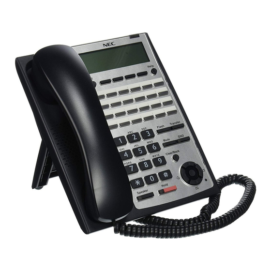
SL1000 ISSUE 1.0 5 INSTALLING THE MULTI-LINE TELEPHONES AND ECTION OPTIONAL TERMINALS 5.1 Installing the Multi-Line Telephones 5.1.1 Location of Controls Handset Alphanumeric Display Indicator Exit Exit Help Help Programmable function keys 24TXH only Flash Flash Transfer Transfer Mute DND/CONF... -
Page 99: Figure 2-105 Leg Setting For Low Position
ISSUE 1.0 SL1000 2. Adjust the Legs to desired height. < Low position > Figure 2-105 Leg Setting for Low Position 3. Lead the Line and Handset cords through the applicable grooves. Handset cord Telephone line cord < Bottom view>... -
Page 100: Figure 2-107 Setting For High Position
SL1000 ISSUE 1.0 2. Pull-up the Leg Stoppers. Leg Stopper Figure 2-107 Setting for High Position 3. Adjust the Legs to desired height. < High position > Figure 2-108 Leg setting for high position 4. Lead the Line and Handset cords through the applicable grooves. (Refer to... -
Page 101: Wall-Mounting The Multi-Line Telephone
ISSUE 1.0 SL1000 5.1.3 Wall-Mounting the Multi-Line Telephone 1. Arrange the cables and put down the leg as shown below. Handset cord Telephone line cord < Bottom view> Figure 2-109 Cabling for Wall-Mount 2. Remove the hook-switch hanger and Insert the hook-switch hanger in the slot below the hook- switch. -
Page 102: Installing The Dss Console
SL1000 ISSUE 1.0 4. Affix the phone to the wall. Wall-mounting holes Wall side Figure 2-112 Affixing the Multi-Line Telephone 5.2 Installing the DSS Console 60D DSS-A Console should be installed to the last hybrid extension ports (ST8/ST16/ST24) of each 408M-A1/408E-A1/008M-A1 card directly. -
Page 103: Figure 2-114 Cabling Of Dss
ISSUE 1.0 SL1000 3. Lead the Line cord through the applicable grooves. Figure 2-114 Cabling of DSS 5.2.1.2 High position setting 1. Turn DSS Console over (button side down). 2. Pull-up the Leg Stoppers. Leg Stopper Figure 2-115 Leg Stopper of DSS Console 3. -
Page 104: Wall-Mounting The Dss Console
SL1000 ISSUE 1.0 4. Lead the Line cord through the applicable grooves. (Refer to Figure 2-114 Cabling of DSS on the previous page) 5.2.2 Wall-Mounting the DSS Console 1. Replace the leg and the cable must be follow as below. -
Page 105: Installing The Headset
ISSUE 1.0 SL1000 3. Affix the DSS Console to the wall. Wall-mounting holes Wall side Figure 2-119 Affixing the DSS 5.3 Installing the Headset The Multi-Line Telephone user can utilize a customer-provided headset in place of the handset. Like using Handsfree, using the headset frees up the user's hands for other work. However, Headset Operation provides privacy not available from Handsfree. -
Page 106: Figure 2-121 Doorphone Box And Bracket
SL1000 ISSUE 1.0 3. Connect the cable to the screw terminals at Doorphone box. (No polarity sensitive) Wall-mount bracket Upper housing Screw terminals Screw Connect cable Figure 2-121 Doorphone Box and Bracket 4. Fix the Wall-Mount bracket on the wall by attached screws. -
Page 107: Connecting The Doorphone
ISSUE 1.0 SL1000 5.4.2 Connecting the Doorphone Wire position for each port Port position ST6 or ST7 Modular cable (2-wire, Straight) Door phone Figure 2-123 Connecting the Doorphone The Doorphone configuration shall be assigned by system programming. The 3 party Doorphone Boxes can not be connected to the port. -
Page 108: Installing The Door Unlock Devices
SL1000 ISSUE 1.0 5.5 Installing the Door Unlock Devices Up to 2 door unlock devices can be connected to per a KSU. J7 (RJ61) 8 765 4321 Door unlock control devices Figure 2-124 Connecting the Door Unlock Device Following table shows the pin-outs for the RJ-61 cable connector. -
Page 109: Installing The External Paging Speaker/External Moh/Bgm Sources
ISSUE 1.0 SL1000 5.6 Installing the External Paging Speaker/External MOH/BGM Sources 5.6.1 Connecting the Audio Equipment • The trunk ports CO2 to CO4 can be used for audio port (External paging, External MOH, BGM) • Audio port configuration shall be assigned by system programming. -
Page 110: Bgm/External Moh Source Input Specifications
SL1000 ISSUE 1.0 5.6.3 BGM/External MOH Source Input Specifications Table 2-25 BGM/External MOH Source Input Specifications Item Specification Input Impedance @ 1 kHz Input Level Nominal 250 mV (-10 dBm) Maximum Input 1 V RMS 5.7 SMDR (Station Message Detail Recording) 5.7.1 General... -
Page 111: Chapter 3 System Start Up
System Start Up 1 SYSTEM START UP ECTION 1.1 Before Starting Up the System Before starting up the system, make sure: • KSU(s) is/are installed correctly. • All extensions are cabled correctly. • All earth ground and PSTN Trunks are cabled correctly. •... -
Page 112: Perform A Cold Start
SL1000 ISSUE 1.0 1.2.1 Perform a Cold Start This section describes the process for starting the system for the first time or starting a system that requires the customer data deleting. System software is loaded from flash memory, and the customer data is deleted from RAM memory. -
Page 113: Perform A Hot Start
ISSUE 1.0 SL1000 6. Continue holding the Load button (S1) for approximately three second or until Status LED (D5) starts flashing red. RUN LED LED (D5) < Front view > Figure 3-4 Status LED (D5) and RUN LED Location 7. Release the Load button. -
Page 114: Section 2 Programming Mode
SL1000 ISSUE 1.0 2 PROGRAMMING MODE ECTION 2.1 Entering the Programming Mode The installer/system administrator can enter to the system programming mode from the Display Type Multi-Line Telephone. (Up to 2 users can enter to the mode at the same time) In a newly installed system, use extension port 1. -
Page 115: Loading The Customer Data
ISSUE 1.0 SL1000 CPU card CF slot (CN2) CF card PZ-VM21 PCB Figure 3-10 Inserting the CF card 2. Turn the power on, enter to the PRG90-03 at the Programming Mode. Figure 3-11 PRG90-03 Display 3. Dial 1 and press Hold key. -
Page 116: Figure 3-13 Inserting The Cf Card
SL1000 ISSUE 1.0 1. Turn the power off, insert the Customer Data CF card to the CF Slot on PZ-VM21. CPU card CF Slot (CN2) CF card PZ-VM21 PCB Figure 3-13 Inserting the CF Card 2. Turn the power on, enter to the PRG90-04 at the Programming Mode. -
Page 117: Section 3 System Shut Down
ISSUE 1.0 SL1000 3 SYSTEM SHUT DOWN ECTION 3.1 Powering Off the System 1. Turn the all KSU(s) power off by the power switch. Figure 3-16 Power Switch Location • If the Expansion KSU(s) is/are installed, turn the power on/off in the order of Exp 3 KSU, Exp 2 KSU, Exp 1 KSU and then Main KSU. - Page 118 SL1000 ISSUE 1.0 Memo System Start Up...
-
Page 119: Chapter 4 Maintenance
Maintenance 1 FUSE REPLACEMENT ECTION 1.1 Replacing the Fuse If the Expansion KSU(s) is/are installed, turn the power on/off in the order of Exp 3 KSU, Exp 2 KSU, Exp 1 KSU and then Main KSU. 1. Turn off the system power and disconnect AC cord. 2. -
Page 120: Figure 4-2 Removing The Main-Cover
SL1000 ISSUE 1.0 3. Loosen two screws and remove the Main-cover. Main-Cover Two screws Hooks Figure 4-2 Removing the Main-cover 4. Exchange the fuse (250 V/8 A) on 408M-A1 PCB. 408M-A1 FUSE (8 A / 250 V) < Top View >... -
Page 121: Figure 4-4 Replacing The Main-Cover
ISSUE 1.0 SL1000 5. Replace the Main-cover and fasten two screws. Main-Cover Two screws Hooks Figure 4-4 Replacing the Main-Cover Hardware Manual... -
Page 122: Section 2 Lithium Battery Replacement
SL1000 ISSUE 1.0 2 LITHIUM BATTERY REPLACEMENT ECTION 2.1 General The Lithium Battery (CR2032) is initially installed on the CPU Card in Main KSU. It provides the battery-backup of the RAM memory for approximately 36 months. When the battery life becomes almost over, the system will inform the "Warning Message"... -
Page 123: Replacing The Lithium Battery
ISSUE 1.0 SL1000 2.3 Replacing the Lithium Battery 1. Remove the Sub-cover at the main KSU. Sub-Cover Figure 4-6 Removing the Sub-cover 2. Power off the system, and remove the AC plug from the AC outlet. 3. Disconnect the AC power cord from the KSU. -
Page 124: Figure 4-8 Removing The Main-Cover
SL1000 ISSUE 1.0 4. Loosen two screws and remove the Main-cover. Main-Cover Two screws Hooks Figure 4-8 Removing the Main-cover 5. Press A-part in following figure and open the CPU support. 6. Remove CPU card from the Main KSU. CPU card... -
Page 125: Figure 4-10 Location Of Lithium Battery Socket
ISSUE 1.0 SL1000 7. Refer to following figure for the Lithium battery location on the CPU card. CPU card Battery socket < Conductor side > Figure 4-10 Location of Lithium Battery Socket 8. Remove the old Lithium battery and insert new one to the socket. -
Page 126: Figure 4-13 Installing The Cpu Card
SL1000 ISSUE 1.0 9. Replace the CPU card. CPU card CPU support 408M-A1 at 1632M KSU Figure 4-13 Installing the CPU Card 10. Replace the Main-cover and Sub-cover. Maintenance... -
Page 127: Section 3 Main Software Upgrading
• Prepare the CF Card (32MB, or upwards and formatting by FAT(16)), and store the new main software on the CF card by PC. (New Main software shall be supplied from NEC.) • Prepare the PZ-VM21 PCB. (if the system does not have it.) 3.3 Main Software Version Confirmation... -
Page 128: Figure 4-15 Removing The Sub-Cover
SL1000 ISSUE 1.0 2. Remove the Sub-Cover. Sub-Cover Figure 4-15 Removing the Sub-cover 3. Loosen two screws and remove the Main-cover. Main-Cover Two screws Hooks Figure 4-16 Removing the Main-cover 4. Insert the CF card (with the new Main software loaded) to the CF slot on PZ-VM21 daughter board. -
Page 129: Table 4-1 Status Leds
ISSUE 1.0 SL1000 5. Push in and hold the Load button (S1 on the CPU card). Sub-Cover CPU card < Front view > Figure 4-18 Load Button (S1) Location 6. Turn the system power on. 7. Continue holding the Load button (S1) for approximately 10 seconds or until Status LED (D5) starts flashing red. - Page 130 SL1000 ISSUE 1.0 13. When the system has completed reloading the software, the RUN LED (D1) is flashing blue. • To confirm the new software version number by press Navigation key on any display telephone to view the system version number.
-
Page 131: Section 4 Led Indications
ISSUE 1.0 SL1000 4 LED INDICATIONS ECTION The LEDs on the CPU indicate the following: • RUN (D1) = The CPU is operating (Blue) • D2, and D3 = Alarms (Red) • D4 = Flash access indication (Red) • D5 = Boot status (Red) •... - Page 132 SL1000 ISSUE 1.0 Memo 4-14 Maintenance...
-
Page 133: Section 1 System Capacity
Specifications 1 SYSTEM CAPACITY ECTION Table 5-1 System Capacity Items 1 KSU 2 KSU 3 KSU 4 KSU Remarks Trunk port Max. 1KSU: 408M + PRI x1 + 408E x2 2KSU: (408M + PRI x1 + 408E x2) x2 3/4KSU: (408M + PRI x1+408E x2) x3 Trunk Analog Trunk 1KSU: 408M + 408E x3... - Page 134 SL1000 ISSUE 1.0 Items 1 KSU 2 KSU 3 KSU 4 KSU Remarks VM/VRS Channels 2 VM ports/ 4 VRS ports (default) CFVMS-C1 (512M) (Total Max.8 w/o MEMDB or 16 w/MEMDB) Port incresed by license. 4 VM ports/ 4 VRS ports (default) CFVML-C1 (1G) (Total Max.8 w/o MEMDB or 16 w/MEMDB)
-
Page 135: Section 2 System Specifications
ISSUE 1.0 SL1000 2 SYSTEM SPECIFICATIONS ECTION 2.1 General Precautions • Never attempt to insert wires, pins, etc. into the vents or other holes of the equipment. • Do not use benzene, thinner, or the like, or any abrasive powder to clean the equipment. Wipe it with a soft cloth. -
Page 136: Electrical Specifications
SL1000 ISSUE 1.0 110 VAC 220 VAC 230 VAC 240 VAC Grounding Require- No.14 AWG Copper Wire ment Feeding Voltage SLT: 20 mA/-27 V AC Input I Main KSU = 1.31 A Main KSU = 0.78 A Main KSU = 0.76 A Main KSU = 0.73 A...(Per A Ksu) -
Page 137: Doorphone Interface Specifications
ISSUE 1.0 SL1000 Unit Width (mm) Depth (mm) Height (mm) Weight (kg) PZ-VM21 0.03 IP4WW-408E-A1 0.21 IP4WW-008E-A1 0.18 IP4WW-000E-A1 0.12 IP4WW-1PRIU-C1 0.15 IP4WW-2BRIDB-C1 0.09 IP4WW-EXIFB-C1 0.04 IP4WW-CFVRS-C1 0.01 IP4WW-CFVMS-C1 0.01 IP4WW-CFVML-C1 0.01 2.9 Doorphone Interface Specifications Table 5-7 Doorphone Interface Specifications... -
Page 138: External Sensor Device Interface Specifications
SL1000 ISSUE 1.0 Item Specification Input Level Nominal 250 mV (-10 dBm) Maximum Input 1 V RMS 2.13 External Sensor Device Interface Specifications Table 5-11 External Sensor Device Interface Specifications Applied Voltage during Loop Current during Sensor Port Assignment Sensor Off... - Page 139 ISSUE 1.0 SL1000 Device Cable Type Cable Run Length (m) ISDN Terminal 4-wire, 24 AWG (Φ0.5 mm) 100 (P-MP Short-passive) 300 (P-MP Long-passive) 500 (P-P) 1632ME-A1 EXP Ethernet Straight Cable (Attached to 1632ME-A EXP) Hardware Manual...
- Page 140 SL1000 ISSUE 1.0 Memo Specifications...
- Page 141 ISSUE 1.0 SL1000 Memo Hardware Manual...
- Page 142 Hardware Manual NEC Corporation ISSUE 1.0...