
Related Manuals for Philips LTC2377/50


Summary of Contents for Philips LTC2377/50
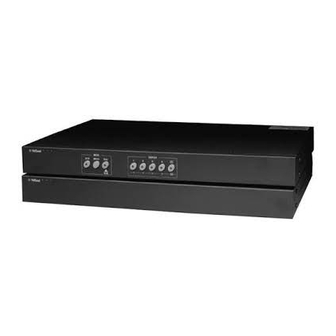
- Page 1 LTC 2372, LTC 2375 LTC 2376, LTC 2377 VidQuad Digital Processor Units...
- Page 2 IMPORTANT SAFEGUARDS 1. Read Instructions - All the safety and operating instructions should be read before the unit is operated. 2. Retain Instructions - The safety and operating instructions should be retained for future reference. 3. Heed Warnings - All warnings on the unit and in the operating instructions should be adhered to.
-
Page 3: Table Of Contents
230 VAC, 50 Hz 195.5 to 253 12 W SERVICE If the unit ever needs repair service, the customer should contact the nearest Philips Communication & Security Systems Service Center for authorization to return and shipping instructions. DESCRIPTION LTC 2372 & LTC 2375... - Page 4 Note: To eliminate vertical roll during sequencing, (Quad to camera 1 only) the VidQuad output synchronizes to input 1. For the LTC 2377 series, it is recommended to have a color camera as camera 1. PHILIPS TRIG Looping (Automatic Termination) Power...
-
Page 5: Installation
REMOTE Alarm Contact PHILIPS Main Monitor Fig. 3: Configuration for LTC 2376 and LTC 2377 VidQuad Digital Processor Unit with Monitor Option INSTALLATION LTC 2372 and LTC 2375 Connection Item VidQuad Digital Processor Camera 1 Video Input 1 - BNC... - Page 6 LTC 2376 and LTC 2377 Connection ALARM OUT ALARM IN REMOTE NCCOMNO G S COM 1 RELAY Item VidQuad Digital Processor Video Inputs Camera 1 Video Input 1 - BNC Camera 2 Video Input 2 - BNC Camera 3 Video Input 3 - BNC Camera 4 Video Input 4 - BNC Video Outputs...
-
Page 7: Ltc 2372 & Ltc 2375
Functions of each key on the front panel are described in the table above. > < , 2/ , 3/ , 4/ , and are used in keys are not used in ALM ( ) PHILIPS PHILIPS... -
Page 8: Time And Date
Time and Date This menu allows you to set the date and time format, the current time/date and displayed position on the monitor. Select TIME/DATE and press the menu is displayed: (1) TIME FORMAT (2) DATE FORMAT (3) TIME/DATE SET (4) DISPLAY : BOTTOM (5) EXIT 5.3.1... -
Page 9: Alarm Setup
Press the key to increase the dwell time. Dwell times may be programmed from SKIP to 9 seconds. (When you reach 9 seconds, pressing the key will toggle you through the sequence again. A setting of "SKIP" removes the channel from the sequence. Select EXIT and press the key to exit the menu. -
Page 10: Vcr Out Mode
5.5.4 Video Loss Alert The VIDEO LOSS ALERT function enables you to define if an alarm is generated when any of the video inputs is lost/defective. Select VIDEO LOSS ALERT and press the following menu is displayed: VIDEO LOSS ALERT (1) CHANNEL 1: ON (2) CHANNEL 2: ON (3) CHANNEL 3: OFF... -
Page 11: Color Adjustment
CAMERA 1 TITLE SET CAMERA 1 TO EXIT PRESS ENTER KEY < > Press the keys to move the cursor to the required position. Press the keys to select the required character. Press the key to return to the CAMERA TITLES menu. Select EXIT and press the key to exit the menu. -
Page 12: Set The Password
Set the Password The unit incorporates a password function for entry to the menu operation. This ensures that only authorized persons can change the unit settings. Select PASSWORD SET and press the following menu is displayed: PASSWORD SETTING (1) NEW PASSWORD (2) DISABLE PASSWORD (3) EXIT Press the... -
Page 13: Operation
VCR key again switches the unit to the sequential switching mode. If the Quad unit is running in the programming mode, using by the EXIT key switches the unit to the sequential switching mode. 1.13 PHILIPS PHILIPS " key: Display VCR video as recorded. - Page 14 6.2.4 Manual Switching Press the 1, 2, 3, or 4 key to select manual switching. The selected quadrants will be displayed in full screen mode. The camera title of the selected quadrant is displayed in the center of the monitor screen. If the Quad unit is operating in the VCR or programming mode, you can not use manual switch mode.
-
Page 15: Maintenance
Signal format is as follows: 1 Data Format: 1,200 Baud / 8 Data Bit / No Parity / One Stop Bit 2 Mode: Half Duplex Mode (The unit is not Echo Received Character.) Table - (RS-232 Commands) COMMAND RS-232 CODE VCR input Enter the programming mode Sequence/Reset...