
Related Manuals for Philips BLF278


Summary of Contents for Philips BLF278
- Page 1 DISCRETE SEMICONDUCTORS DATA SHEET M3D091 BLF278 VHF push-pull power MOS transistor Product Specification Supersedes data of 1996 Oct 21 2003 Sep 19...
- Page 2 CAUTION This product is supplied in anti-static packing to prevent damage caused by electrostatic discharge during transport and handling. For further information, refer to Philips specs.: SNW-EQ-608, SNW-FQ-302A, and SNW-FQ-302B. QUICK REFERENCE DATA RF performance at T = 25 C in a push-pull common source test circuit.
- Page 3 Philips Semiconductors VHF push-pull power MOS transistor LIMITING VALUES In accordance with the Absolute Maximum System (IEC 60134). SYMBOL PARAMETER Per transistor section drain-source voltage gate-source voltage drain current (DC) total power dissipation storage temperature junction temperature THERMAL CHARACTERISTICS SYMBOL...
- Page 4 Philips Semiconductors VHF push-pull power MOS transistor CHARACTERISTICS = 25 C unless otherwise specified. SYMBOL PARAMETER Per transistor section drain-source breakdown voltage V (BR)DSS drain-source leakage current gate-source leakage current gate-source threshold voltage GSth gate-source voltage difference of both sections...
- Page 5 Philips Semiconductors VHF push-pull power MOS transistor handbook, halfpage T.C. (mV/K) = 10 V. Fig.4 Temperature coefficient of gate-source voltage as a function of drain current; typical values per section. handbook, halfpage R DSon (m ) = 10 V; I = 5 A.
-
Page 6: Application Information
Philips Semiconductors VHF push-pull power MOS transistor handbook, halfpage C rs (pF) = 0; f = 1 MHz. Fig.8 Feedback capacitance as a function of drain-source voltage; typical values per section. APPLICATION INFORMATION Class-B operation RF performance in CW operation in a common source push-pull test circuit. T otherwise specified. - Page 7 Philips Semiconductors VHF push-pull power MOS transistor handbook, halfpage (dB) Class-B operation; V = 50 V; I = 3.2 + j4.3 (per section); R (1) T = 25 C. (2) T = 70 C. Fig.9 Power gain as a function of load power;...
- Page 8 white to force landscape pages to be rotated correctly when browsing through the pdf in the Acrobat reader. white to force landscape pages to be ... handbook, full pagewidth input V DD1 V DD1 D.U.T. L3 L5 L7 L4 L6 L8 V DD2 Fig.12 Class-B test circuit at f = 108 MHz.
- Page 9 Philips Semiconductors VHF push-pull power MOS transistor List of components (see Figs 12 and 13). COMPONENT DESCRIPTION C1, C2, C33, C34 multilayer ceramic chip capacitor; note 1 C3, C4 multilayer ceramic chip capacitor; note 1 C5, C6, C28 film dielectric trimmer multilayer ceramic chip capacitor;...
- Page 10 Philips Semiconductors VHF push-pull power MOS transistor COMPONENT DESCRIPTION L17, L18 stripline; note 2 L19, L20 stripline; note 2 L21, L23 stripline; note 2 semi-rigid cable; note 3 metal film resistor R2, R7 10 turn potentiometer R3, R6 metal film resistor R4, R5 metal film resistor...
- Page 11 Philips Semiconductors VHF push-pull power MOS transistor handbook, full pagewidth strap strap V DD1 input Dimensions in mm. The circuit and components are situated on one side of the PTFE fibre-glass board, the other side being fully metallized to serve as an earth.
- Page 12 Philips Semiconductors VHF push-pull power MOS transistor handbook, halfpage Class-B operation; V = 50 V; I (per section); P = 300 W. Fig.14 Input impedance as a function of frequency (series components); typical values per section. handbook, halfpage Fig.16 Definition of MOS impedance.
- Page 13 Philips Semiconductors VHF push-pull power MOS transistor Class-AB operation RF performance in CW operation in a common source push-pull test circuit. T otherwise specified. R = 2.8 MODE OF OPERATION CW, class-AB Ruggedness in class-AB operation The BLF278 is capable of withstanding a load mismatch corresponding to VSWR = 7:1 through all phases under the following conditions: V = 50 V;...
- Page 14 Philips Semiconductors VHF push-pull power MOS transistor handbook, halfpage (dB) Class-AB operation; V = 50 V; I = 0.74 + j2 (per section); R = 2.8 (1) T = 25 C. (2) T = 70 C. Fig.18 Power gain as a function of load power;...
- Page 15 white to force landscape pages to be rotated correctly when browsing through the pdf in the Acrobat reader. white to force landscape pages to be ... input V DD1 V DD1 D.U.T. L6 L8 L10 C21 C28 L7 L9 L11 V DD2 Fig.21 Class-AB test circuit at f = 225 MHz.
- Page 16 Philips Semiconductors VHF push-pull power MOS transistor List of components (see Figs 21 and 22). COMPONENT DESCRIPTION C1, C2 multilayer ceramic chip capacitor; note 1 C3, C4, C31, C32 multilayer ceramic chip capacitor; note 1 film dielectric trimmer C6, C30 film dielectric trimmer...
- Page 17 Philips Semiconductors VHF push-pull power MOS transistor COMPONENT DESCRIPTION L14, L17 grade 3B Ferroxcube wideband HF chokes in parallel L15, L16 turns enamelled 2 mm copper wire L18, L19 stripline; note 2 L20, L21 stripline; note 2 metal film resistor...
- Page 18 Philips Semiconductors VHF push-pull power MOS transistor handbook, full pagewidth strap Hollow rivets strap V DD1 input Dimensions in mm. The circuit and components are situated on one side of the PTFE fibre-glass board, the other side being fully metallized to serve as an earth.
- Page 19 Philips Semiconductors VHF push-pull power MOS transistor handbook, halfpage –2 Class-AB operation; V = 50 V; I = 2.8 (per section); P = 250 W. Fig.23 Input impedance as a function of frequency (series components); typical values per section. handbook, halfpage Fig.25 Definition of MOS impedance.
- Page 20 Philips Semiconductors VHF push-pull power MOS transistor BLF278 scattering parameters = 50 V; I = 500 mA; note 1 f (MHz) 0.87 142.1 0.88 159.8 0.88 169.0 0.88 171.2 0.89 172.2 0.91 172.9 0.92 173.5 0.93 174.1 0.94 174.7 0.95 175.2...
-
Page 21: Package Outline
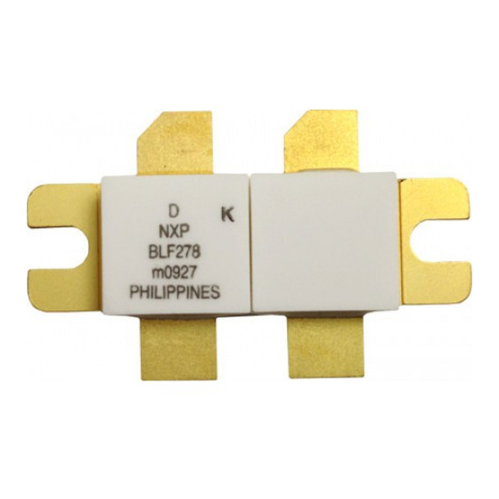
Philips Semiconductors VHF push-pull power MOS transistor PACKAGE OUTLINE Flanged double-ended ceramic package; 2 mounting holes; 4 leads DIMENSIONS (millimetre dimensions are derived from the original inch dimensions) UNIT 5.77 5.85 0.16 22.17 5.58 5.00 0.10 21.46 0.230 0.227 0.006 0.873... -
Page 22: Data Sheet Status
2. The product status of the device(s) described in this data sheet may have changed since this data sheet was published. The latest information is available on the Internet at URL http://www.semiconductors.philips.com. 3. For data sheets describing multiple type numbers, the highest-level product status determines the data sheet status. - Page 23 Contact information For additional information please visit http://www.semiconductors.philips.com. For sales offices addresses send e-mail to: sales.addresses@www.semiconductors.philips.com. © Koninklijke Philips Electronics N.V. 2003 All rights are reserved. Reproduction in whole or in part is prohibited without the prior written consent of the copyright owner.