
Related Manuals for HIKVISION DS-6001FI


Summary of Contents for HIKVISION DS-6001FI
- Page 1 User Manual of Embedded Decoder Server User Manual DS-6001FI Embedded Decoder Server Page 1 Total...
-
Page 2: Table Of Contents
OMMAND AND ERVER 4.2 U ................21 LIENT OFTWARE TO UPGRADE FIRMWARE CHAPTER 5 FREQUENT ASK QUESTIONS ..................22 APPENDIX A DS-6001FI SPECIFICATIONS ..................23 APPENDIX B GOOD LIST........................24 APPENDIX C CUSTOMER INFORMATION CARD ................25 Page 2 Total... - Page 3 User Manual of Embedded Decoder Server Thanks for purchasing the products of Hikvision. If you have any requests or questions, please contact us immediately. This manual is applicable to DS-6001FI Decoding Video Server This manual may contain some technically incorrect places or printing errors.
-
Page 4: Chapter 1 Introduction
Firmware is burned into the FLASH, making the system more steady and reliable. DS-6001FI video server is both an encoder and decoder. It has one channel video input, can compress the video signal into H.264 real time stream, and transmit the live steam through network. -
Page 5: Chapter 2 Installation
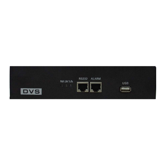
User Manual of Embedded Decoder Server Chapter 2 Installation 2.1 Hardware installation 2.1.1 Installation steps Open packing case, and check the integrity; Take out things needed in installation; Connect cables needed (video signal input cable, audio signal input cable, RS485 cable and cable for LAN);... - Page 6 USB interface (reserved). Back panel: DS-6001FI Rear Panel Interface Instruction(From left to Right in return): For DS-6001FI, there is video input connector on the left side of video output; One line in audio input; One audio output; UTP network interface;...
-
Page 7: The Pin Definition Of Physics Interfaces
User Manual of Embedded Decoder Server 2.3 The pin definition of physics interfaces 2.3.1 PIN definition of RS-232 port The Decoder has one RS232 standard serial interface, with RJ-45 connector. Its pin definition is as follows (‘I’ means input, and ‘O’ means output): (1) When the RS232 interface of the DVS connects with the DTE equipment, one end of the cable is the 8-pin RJ45 connector (to DVS) and the other of the cable is the DB25 female connector (to DTE). - Page 8 User Manual of Embedded Decoder Server (3) If you don’t want to use 25-pin to 9-pin convertor to connect DVS and DTE through RS232 interface, you must use RJ45-DB9 cable. Its internal connection description is: (4) When the RS232 interface of the DVS connects with the DCE (such as MODEM), one end of the cable is the 8-pin RJ45 connector and the other is the DB25 male connector.
-
Page 9: Pin Definition Of Rs485 Port
User Manual of Embedded Decoder Server 2.3.2 PIN definition of RS485 port Pin5 ---- TX+/RX+ Pin 6 ----- TX-/RX- 2.3.3 PIN definition of Ethernet port (1) PIN definition of the direct network cable connecting Decoder and network HUB or switch: (2) PIN definition of the cross network cable connecting Decoder and host PC: - 9 -... - Page 10 User Manual of Embedded Decoder Server - 10 -...
-
Page 11: Chapter 3 Video Server Setup
User Manual of Embedded Decoder Server Chapter 3 Video Server Setup There are three kinds of methods to configure the parameters of video server. 1. Through Hyper Terminal (connect Decoder with the PC through RS-232 serial ports) 2. Through client-end application software (connect Decoder with PC through network) 3.1 Parameter Setup through RS-232 serial port Mainly set up IP parameters of the video server through serial port. - Page 12 User Manual of Embedded Decoder Server Fig. 3.1.1 newly establish a connection and define the name and icon Step2: To name the connection name and to define the icon. Input a name (e.g. aa), select a icon, press “OK”, the dialogue box like Fig. 3.1.2 appears. Fig.
- Page 13 User Manual of Embedded Decoder Server Fig. 3.1.3 Serial ports parameter setup Step 4: Serial port parameters setup. Set the serial port parameters as the following setup: Bits per second: 115200, Data bits: 8, Parity: None, Stop bits: 1, Flow control: None. Press “OK” after finish, the Hyper Terminal interface like Fig.
-
Page 14: Shell Commands Under Hyper Terminal
User Manual of Embedded Decoder Server Fig. 3.1.4 Hyper Terminal Interface Step 5: To close the window, the Fig. 3.1.5 will appear. Select “Yes” and Fig. 3.1.5 will appear. Select “Yes” again to have the Fig. 3.1.6 Fig. 3.1.5 to disconnect Fig. - Page 15 User Manual of Embedded Decoder Server Fig. 3.1.7 Hyper Terminal command prompt Input help, the supported configuration commands can be checked up, as in Fig. 3.1.8. Fig. 3.1.8 to check command The following is the introduction of getIp, setIp commands. getIp Function:to get the fixed IP, subnet mask, gateway, command port, IP address of PPPoE dialup (the IP address of PPPoE will be 0.0.0.0 if there is no dialup or dialup is not successful).
- Page 16 User Manual of Embedded Decoder Server Grammar format: Enter after input the command Explanation: Please pay attention whether the inputting letters are capital or low case. Fig. 3.1.9 to get parameters of IP, PPPoE setIp Function:to set the IP, subnet mask and gateway of the device Parameter:IP address, subnet mask, gateway Grammar format:setIp IP: mask Explanation: Please pay attention whether the inputting letters are capital or low case.
-
Page 17: Ptz Control
User Manual of Embedded Decoder Server 3.2 PTZ control Step1: Connect Decoder RS-485 interface with PTZ. Please refer to RS-485 pin definition. DVS just uses Pin5 (TX+) and Pin6 (TX-) to send PTZ control command. Step2: You can use remote client software to setup PTZ protocol. In client software remote setup dialog box, select “Serial Para”... -
Page 18: Chapter 4 Upgrade Firmware
User Manual of Embedded Decoder Server Chapter 4 Upgrade Firmware There are two methods to upgrade the Decoder firmware. One is using shell commands to ask Decoder to download firmware from FTP server. The other is using PC client software. 4.1 Use Shell Command and FTP Server 1. - Page 19 User Manual of Embedded Decoder Server In the example, I set the Decoder as "192.0.0.95" and ftp server as "192.0.0.144". Of course the ftp server software (wftpd32.exe) is run in the PC whose IP address is "192.0.0.144" and the network is OK. In this case, Decoder (192.0.0.95) will search the PC (192.0.0.144) and download the firmware from ftp server.
- Page 20 User Manual of Embedded Decoder Server - 20 -...
-
Page 21: Use Client Software To Upgrade Firmware
User Manual of Embedded Decoder Server 4.2 Use Client Software to upgrade firmware In the system setup dialog of DVRDVS client software (refer to client software user manual), there is a button named “Upgrade”: Select the DVRDVS, Click “Upgrade” button, the following dialog box will be appeared: Fig.4.21 remote upgrading Click “Browse”... -
Page 22: Chapter 5 Frequent Ask Questions
User Manual of Embedded Decoder Server Chapter 5 Frequent ask questions 1, Failure to control PTZ It is possible that the camera and equipment are not connected through RS485 port, or the wrong configuration of the decoder. 2,certain individual channel picture is un-normal Please check whether the video cable is well connected with the camera and the Embedded DVS 3,Possible reasons which can cause the failure of upgrading... -
Page 23: Appendix Ads-6001Fi Specifications
User Manual of Embedded Decoder Server Appendix A DS-6001FI Specifications Model DS-6001FI Encoder & Decoder Video standard H.264 Compression resolution 4CIF/DCIF/2CIF/CIF/QCIF 1 channel BNC (1.0Vp-p, 75Ω) Video input 1 channel BNC (1.0Vp-p, 75Ω) Video output 4CIF: 25(P)/30(N) fps Frame rate (per channel) -
Page 24: Appendix Bgood List
User Manual of Embedded Decoder Server Appendix B Good List One piece of DS-6001FI decoding server; A CD contains client application; One power supply voltage stabilizer A 220V power cable; A cable connecting RS232 with DTE; A DTE cable - 24 -... -
Page 25: Appendix Ccustomer Information Card
User Manual of Embedded Decoder Server Appendix C Customer Information Card User’s Name Mr./Mrs. Company Name Post Address Postcode Phone Number E-mail Model Number of Product Serial Number of Product Purchase Date Distributor - 25 -... - Page 26 User Manual of Embedded Decoder Server Suggestions: - 26 -...