Advertisement
Quick Links
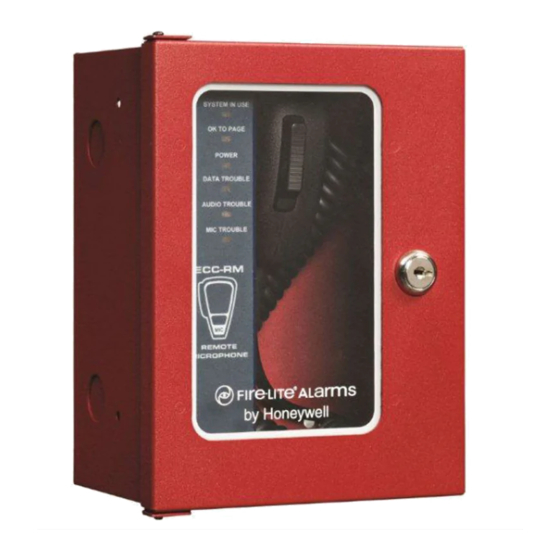
1 Overview
The ECC-RM is an optional Remote Microphone
compatible with the ECC-50/100 Emergency Command
Center. ALL CALL paging can be broadcast over the
speaker circuits by depressing the microphone's push-to-
talk switch. The RM requires an external data bus
connection, an external audio riser connection, and an
external operator interface power connection (24 volts
DC) from the ECC-50/100 main console. Refer to the
ECC-50/100 Manual, LS10001-000FL-E, for more
information.
Figure 1 ECC-RM
NOTE: Installation and wiring of this device must be
done in accordance with NFPA 72 and local ordinances.
2 Installation
2.1 Removing the Bracket/
Microphone Assembly
1.
Unlock the cabinet door.
2.
Remove the two screws holding the assembly in
place.
ECC-RM Remote Microphone
Product Installation Document
PN LS10029-000FL-E:B 8/27/2013 13-739
screw holes
Figure 2 Microphone Assembly Screw locations
3.
Remove the bracket/microphone by sliding the
assembly out of its mounting slots.
4.
Store assembly in a safe location.
mounting slots
Figure 3 Removing the Microphone Assembly
2.2 Mounting the Backbox
1.
Mark and predrill two holes for the top and two for
the bottom of the backbox.
2.
Hold cabinet on wall and tighten down all fasteners to
complete backbox mounting.
One Fire-Lite Place
Northford, CT 06472-1653 USA
203-484-7161 • FAX 203-484-7118
www.firelite.com
Advertisement

Related Manuals for Honeywell Fire-Lite ECC-RM

Summary of Contents for Honeywell Fire-Lite ECC-RM
- Page 1 One Fire-Lite Place Northford, CT 06472-1653 USA 203-484-7161 • FAX 203-484-7118 www.firelite.com ECC-RM Remote Microphone Product Installation Document PN LS10029-000FL-E:B 8/27/2013 13-739 1 Overview The ECC-RM is an optional Remote Microphone compatible with the ECC-50/100 Emergency Command Center. ALL CALL paging can be broadcast over the speaker circuits by depressing the microphone's push-to- talk switch.
-
Page 2: Led Indicators
Carefully reinstall the bracket/microphone assembly. Remember to attach the ground cable. RM board main control board external operator interface power - TB24 mounting holes 24VDC power 4.0” (10.16cm) O.C. external data earth ground audio TB12 lower mounting holes data Figure 4 Backbox Mounting TB22 3 Wiring external...