Honeywell CIU 888 Installation Manual
Hide thumbs
Also See for CIU 888:
- Configuration manual (244 pages) ,
- Migration manual (110 pages) ,
- Troubleshooting and maintenance manual (52 pages)
Table of Contents
Advertisement
Advertisement
Table of Contents

Related Manuals for Honeywell CIU 888


Summary of Contents for Honeywell CIU 888
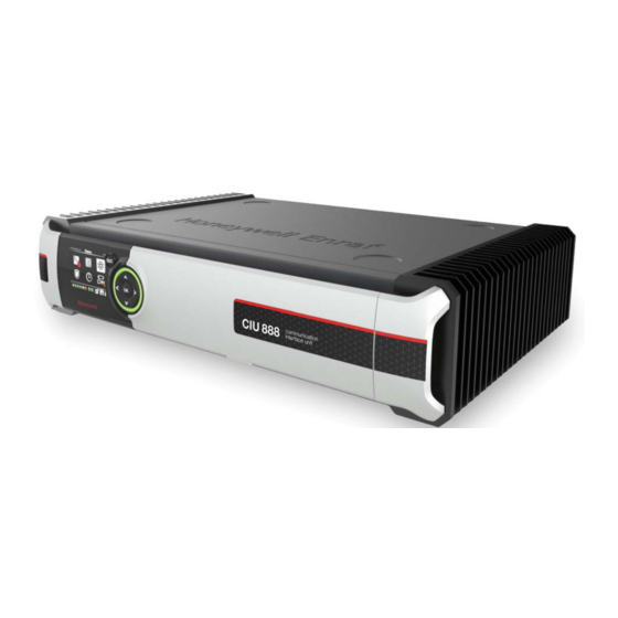
- Page 1 Installation Guide Release R160...
-
Page 2: Table Of Contents
3.3 CIU 888 Interface Summary ........ - Page 3 Table of Contents This page is intentionally left blank Installation Manual Part No.: 4417590_Rev13 CIU 888...
-
Page 4: Chapter 1 Storage, Unpacking And Handling
CHAPTER 1 STORAGE, UNPACKING AND HANDLING 1.1 Unpacking and Inspection Check the identification code on the label to verify that the CIU 888 was delivered in accordance with your order. The CIU 888 is packed in a shipping carton for protection against damage. - Page 5 Storage, Unpacking and Handling - Handling This page is intentionally left blank CIU 888 Part No.: 4417590_Rev13 1 - 2 Installation Manual...
-
Page 6: Chapter 2 Mechanical Installation
Observe country, local and company regulations during all steps of the installation. Only qualified technicians must perform the installation. Honeywell Enraf accepts no responsibility caused by mis-handling, mis- use or faulty operation of the CIU 888. 2.2 Specifications and operational requirements Sl. - Page 7 Mechanical Installation - Specifications and operational requirements 2.2.1 CIU 888 Dimensions 90 [3 SPACE REQUIRED FOR CONNECTION 400 [15 FIGURE 2-1 CIU 888 dimensions CIU 888 Part No.: 4417590_Rev13 2 - 2 Installation Manual...
-
Page 8: Mechanical Installation
2.5.1 Table Top usage The CIU 888 is placed on the desk or a table top. This does not require any special attachment. Place the CIU 888 on a flat surface. Do not place anything on top of the unit. - Page 9 The steps below show the rack mount bracket assembly with the unit. 1. Fix the left bracket (provided as part of rack mount accessories) on the bottom of the CIU 888 by fastening the screws. Repeat the same process for fixing the right bracket on the other side.
- Page 10 Mechanical Installation - Mounting FIGURE 2-3 Fixing the Brackets 2. Mount the CIU 888 on the rack and align the screws to the holes. FIGURE 2-4 Align with Rack Holes and tighten the screws Part No.: 4417590_Rev13 CIU 888 Installation Manual...
- Page 11 CIU 888 assembled in a 19" Rack 2.5.3 Wall Mounting You will need a wall mounting kit for wall mounting CIU 888. f you have not ordered it from the factory, order it as an accessory. See the accessory list provided in this manual.
- Page 12 455 mm FIGURE 2-6 Marking Key Holes 2. Locate the Wall Mount Base Plate over screws and fasten the screws on top and bottom as illustrated in the following figure. Part No.: 4417590_Rev13 CIU 888 Installation Manual 2 - 7...
- Page 13 Foam pads are provided on the face and bottom side of the bracket to provide cushioning to the unit. FIGURE 2-8 CIU 888 Part No.: 4417590_Rev13 2 - 8 Installation Manual...
- Page 14 6. The wall mount clamps are fixed to the base of the unit by means of fasteners on the either sides. FIGURE 2-10 7. Place the unit on the wall mount plate by supporting it on the base of the plate. Part No.: 4417590_Rev13 CIU 888 Installation Manual 2 - 9...
- Page 15 NOTE: Ensure that the top cover is secured behind the tab provided on the base plate so that the unit cannot be removed without lifting it. FIGURE 2-12 Unit is placed behind the tab provided on the base plate CIU 888 Part No.: 4417590_Rev13 2 - 10 Installation Manual...
- Page 16 Latch the Hooks NOTE: Loosen the nut behind the hook to adjust the height of the hook. CAUTION! Ensure the hook positions on both sides are main- tained at the same length. Part No.: 4417590_Rev13 CIU 888 Installation Manual 2 - 11...
- Page 17 9. Press the latching clip on both sides, to snap with the hook. Once it is snapped with the clip, the hook is pulled back and the unit is held securely. FIGURE 2-14 Securing the Unit CIU 888 Part No.: 4417590_Rev13 2 - 12 Installation Manual...
- Page 18 Mechanical Installation - Mounting 10. All the cables terminating on the CIU 888 unit are tied to the mounting bracket using the slots with cable ties as shown in the following figure: ≥ 90mm FIGURE 2-15 Cable Tray Part No.: 4417590_Rev13...
- Page 19 Mechanical Installation - Mounting This page is intentionally left blank CIU 888 Part No.: 4417590_Rev13 2 - 14 Installation Manual...
-
Page 20: Chapter 3 Electrical Installation
CAUTION! Check if the mains supply voltage falls within the specified limits of 100-240 V CIU 888 has been supplied with a C13 plug on the CIU 888 side and open end wires on the Line socket side. You can install country specific plug to these open end wires and use it. -
Page 21: Ciu 888 Interface Summary
Electrical Installation - CIU 888 Interface Summary 3.3 CIU 888 Interface Summary CIU 888 Front View USB Port W&M Key Lock Service Port Configuration Key Lock Sync Port Bezel Product Label W&M Key LCD Display ESC Button Configuration Key Navigation Buttons... -
Page 22: Field And Host Port Connections
3.4 Field and Host Port Connections 3.4.1 Enraf Field Bus (BPM Port) A maximum of 80 gauges can be connected to the CIU 888. Gauges should be divided over the field ports with a recommended maximum of 15 instruments per line. Best results are obtained when the Enraf field bus signal to the gauges is connected in a “star”... - Page 23 Rmax: 200 (per line) Cmax:1 uF (to each other and to ground) NOTE: To prevent cross-talk, only individually shielded twisted pairs should be used in a multi-core cable. CIU 888 Part No.: 4417590_Rev13 3 - 4 Installation Manual...
- Page 24 Electrical Installation - Field and Host Port Connections 3.4.2 TRL/2 Field Bus A maximum of 48 gauges can be connected to the CIU 888. Gauges should be divided over the field ports with a recommended maximum of 8 instruments per line. Best results are obtained when the TRL/2 field bus signal to the gauges can be connected in a “Multi-drop”...
- Page 25 (Communications Interface Unit) can be placed in any of the option slots 1 to 6. These ports have galvanic isolation. See the section 3.3 "CIU 888 Interface Summary" for locating the ports. 3.4.3.1 Field RS232-485 Port in RS232C mode [Part of a future release] Refer to FIGURE 3-6 for RS-232C pin configuration and connections.
- Page 26 Pin layout for 9 and 25 pins D-type connector Pin no. Signal Name 9 Pins 25 Pins Protective ground Chassis Signal ground CIU 888 CIU 888 (female) (female) Prot Ground Prot Ground Sign. gnd Sign. gnd Sign. gnd Sign.
- Page 27 Electrical Installation - Field and Host Port Connections Direct connection can only be made if the CIU 888 and the DTE (CIU 888 or host computer system) are grounded at the same point. In all other cases, ensure there is at least a proper galvanic isolation at the DTE side.
-
Page 28: Host Rs232-485 Ports (Modbus Output)
Ports are not galvanically isolated. 3.6 Ethernet Ports CIU 888 has 6 Ethernet ports, one on front side and 5 on rear side of CIU 888. All ports are 10/100 Mbps compliant and support Auto MDIX support (auto detects Straight or Cross cable and switches accordingly). -
Page 29: Usb Ports
Electrical Installation - USB Ports 3.7 USB Ports CIU 888 has 3 USB ports, one on the front side and two on the rear side. Back ports are designed to interface with keyboard and mouse. These are low power devices and require currents less than 100 mA for normal operation. -
Page 30: Relay Or Do Outputs [Part Of A Future Release]
Shield: Signal Ground 3.11 Relay or DO Outputs [Part of a future release] CIU 888 has two relay outputs. They are also called digital outputs (as they offer make or break connections). Refer to port details chapter for locating this connector. -
Page 31: Key Locks
W&M and Configuration Key Locks 3.13 User Interface LCD, Navigation Key & Ring of Light CIU 888 on its front bezel has an LCD module and Key pad for user interface and configuration. A Ring of light to display status. FIGURE 3-11... - Page 32 Front Bezel has an LCD with 240 x 320 color pixels. This LCD is used as the local HMI for CIU 888. It also has four navigation keys with one “OK” button in center and also a separate “Esc” (Escape) button to operate the screens on LCD.
- Page 33 Electrical Installation - User Interface This page is intentionally left blank CIU 888 Part No.: 4417590_Rev13 3 - 14 Installation Manual...
-
Page 34: Chapter 4 Appendix A: List Of Spares And Accessories
ETHERNET CABLE 2M BLUE 4217067 ETHERNET CABLE 3M RED 4217068 ETHERNET CABLE 3M GREY Cable Mount Accessories 6759081 CABLE CLAMP A0888903 Mounting Plate for Wall mount positioning TABLE 4-1 List of Spares Part No.: 4417590_Rev13 CIU 888 Installation Manual 4 - 1... - Page 35 FUSE DRWR FOR PWR MOD F'GRIP 2PL 2655084 FUSE 250V UL SLOBLO 5x20MM 2A S0888906 COMPACT FLASH, 4G 2849906 COMPACT FLASH, 4G S0888907 CIU 888 POWER SUPPLY + THERMAL PAD 3862297 AC-DC POWER SUPPLY 75W 12VDC 6406013 SCREW PAN PH, M3x5mm 6476503 CIRCLIP, M3SS DIN125A-A2 0187509 THERMAL PAD 195.0x33.0x1.0mm...
- Page 36 +1 800 423 9883 or +1 215 641 3610 E-mail: HFS-TAC-SUPPORT@honeywell.com Copyright © 2020 - Honeywell All rights reserved. No part of this manual may be reproduced in any form, by print, photoprint, microfilm or any other means without the written permission from Honeywell.
- Page 37 For More Information To learn more about Honeywell Enraf’s solutions, contact your Honeywell Enraf account manager or visit www.honeywellenraf.com. Americas Asia Pacific Honeywell Enraf Americas, Inc. Honeywell Pte Ltd. 1250 West Sam Houston Pkwy S. 17 Changi Business Park Central 1...