Honeywell Touchpoint Plus Technical Handbook
Hide thumbs
Also See for Touchpoint Plus:
- Technical handbook (153 pages) ,
- User manual (71 pages) ,
- Safety manual (8 pages)
Table of Contents
Advertisement
Quick Links
Download this manual
See also:
User Manual
Advertisement
Chapters
Table of Contents

Related Manuals for Honeywell Touchpoint Plus


Summary of Contents for Honeywell Touchpoint Plus
- Page 1 I Gas Detection Touchpoint Plus Technical Handbook...
- Page 2 Added new chapters, new data and final translations 09/06/2015 Issue 03 Completely Revised; added Expansion Unit, Dual Input Module and Modbus 29/02/2016 Issue 04 Added new chapters; added SIL2 and ATEX certification 22/01/2019 MAN0984_Iss 4_01/19 Touchpoint Plus Pt. No. 3011M5001 Technical Handbook...
- Page 3 Conditions of Use Disclaimer In no event shall Honeywell be liable for any damages or injury of any nature or kind, no matter how caused, that arise from the use of the equipment referred to in this manual. Strict compliance with the safety procedures set out and referred to in this manual, and extreme care in the use of the equipment, are essential to avoid or minimise the chance of personal injury or damage to the equipment.
- Page 4 This page is deliberately left blank. MAN0984_Iss 4_01/19 Touchpoint Plus Pt. No. 3011M5001 Technical Handbook...
-
Page 5: Table Of Contents
3.2.7 Storage Conditions (With batteries) ..................... 25 3.2.8 IP Rating ................................25 3.2.9 Construction ..............................25 3.2.10 Touchpoint Plus Packaging ........................26 3.2.11 Packaging Components for Return to Manufacturer ............... 26 3.2.12 Disposal (WEEE Directive) ........................26 3.3 TPPL Construction ............................ 26 3.3.1 TPPL Basic Control Unit .......................... - Page 6 6.16 Backing Up the Configuration Settings ..................79 6.16.1 How to Back Up the Configuration: ....................79 6.16.2 How to Restore the Configuration ...................... 80 Chapter 7. Touchpoint Plus User Guide ..................81 MAN0984_Iss 4_01/19 Touchpoint Plus Pt. No. 3011M5001...
- Page 7 9.1 How to Decommission and Remove a Serviceable I/O Module ..........112 9.1.1 To Remove a Serviceable Module ......................112 9.2 How to Replace a Faulty I/O Module ....................113 9.2.1 To Replace a Faulty Module ........................113 MAN0984_Iss 4_01/19 Touchpoint Plus Pt. No. 3011M5001 Technical Handbook...
- Page 8 9.7.2 How to Replace the Backup Battery ....................120 9.8 Return to Factory Default Settings ....................121 9.8.1 To Reset the Touchpoint Plus to its Factory Default Settings ..........121 Chapter 10. Troubleshooting ......................122 10.1 Calling for Technical Support......................122 Chapter 11.
-
Page 9: Chapter 1. Important Information
1.1 Regulatory Approval Markings Products bearing the CE mark conform to all applicable European Directives as stated on the Honeywell product specific EC Declaration of Conformity. Products bearing the UL mark conform to the requirements for Ordinary Locations. The letters C and US mean that the product is additionally certified for use in Canada and the United States of America. -
Page 10: Tppl General Warnings
Refer to local, national and company regulations. Do not operate the Touchpoint Plus system or its components outside of their rated operating specification. Touchpoint Plus must not be operated in Oxygen enriched atmospheres, i.e. greater than 25% v/v Oxygen. -
Page 11: Tppl General Cautions
2) Do not use sharp objects to operate the Touchscreen as this could irreparably damage the User Interface and adversely affect its IP rating. 3) Use only soft, damp cloths or screen wipes to clean the Touchpoint Plus. Do not use solvents or abrasives as they will cause irreparable damage. -
Page 12: Associated Manuals
OEMs and Modbus specialists only. Note: Refer to Chapter 16 for a list of remote sensors. Refer to the manuals and instructions relevant to the gas sensors and detectors working with Touchpoint Plus. MAN0984_Iss 4_01/19 Touchpoint Plus Pt. -
Page 13: Chapter 2. Safety Hazards, Warnings And Cautions
25% v/v O Touchpoint Plus is suitable for use in Class I, Division 2, Groups A, B, C, and D, or non-hazardous locations only. -
Page 14: Safety Hazards
Touchpoint Plus is Not ATEX/IECEx certified, and it shall only be installed in safe areas where there are no flammable atmospheres, and where oxygen concentrations cannot exceed 25% v/v O Touchpoint Plus is suitable for use in Class I, Division 2, Groups A, B, C, and D or non-hazardous locations only. - Page 15 Do not place objects on the enclosures. CAUTION RISK OF EYE INJURY Touchpoint Plus uses high energy AC and DC currents that may cause arcing and sparks if shorted out. Always wear eye protection when the enclosure is open. CAUTION RISK OF HEARING DAMAGE Touchpoint Plus can be used to control loud alarms and sirens.
-
Page 16: Location And Description Of Warning Labels
This Equipment Earth (Ground) location point label is used inside the system and is not normally visible is used inside the system and is not normally visible to the operator. to the operator. Internal Label Positions MAN0984_Iss 4_01/19 Touchpoint Plus Pt. No. 3011M5001 Technical Handbook... -
Page 17: Electrical Hazards
Read the relevant manual before beginning any operating or service procedures. • Only personnel trained and certified by Honeywell are authorised to service, fit or remove internal parts. • Only the minimum number of trained personnel, consistent with safety, should have access to the area while work is being carried out. -
Page 18: Good Practice
Antistatic Precautions As with all modern electronic circuits, the Printed Circuit Boards (PCBs) in Touchpoint Plus systems utilise some static-sensitive components that can be severely damaged if subjected to static discharge. Static can be generated on the human body by friction or movement and is discharged through the first contacted route to earth. It can also jump gaps between items of differing electrical potential. -
Page 19: Product Compliance
Check the product rating plate and look for the following marks to ensure that the supplied equipment is suitable for its intended location and purpose: Products bearing the CE mark conform to all applicable European Directives as stated on the Honeywell product specific EC Declaration of Conformity. -
Page 20: Training Of Personnel
2.5 Firmware and EEPROM update User is responsible for verification of all settings of Touchpoint Plus after successful update of software (e.g. Ch 6.16.2 How to Restore the Configuration, Ch 9.5.2 To Restore the Configuration From a Backup File and Ch 9.6.2 How to Update the Firmware). -
Page 21: Chapter 3. System General Description
Cable entry is via entry glands on the lower side. Touchpoint Plus is rated IP65, which means that it is dustproof and can be subjected to low-pressure water without significant ingress. This makes it particularly suited to offices, control rooms and unheated boiler rooms. - Page 22 Enclosure TPPL Controller Exploded View Both the Touchpoint Plus and its optional expansion unit have the option for AC, DC and battery backup power supplies, but the optional Expansion Unit has no motherboard or display (LCD). Features of the Controller unit: •...
-
Page 23: How To Open And Close The Enclosure
CAUTION TPPL enclosures must be fully closed and secured during normal operation. MAN0984_Iss 4_01/19 Touchpoint Plus Pt. No. 3011M5001 Technical Handbook... -
Page 24: Equipment Specification
3.2 Equipment Specification 3.2.1 Power Requirements (Controller Unit only) The Touchpoint Plus system is designed to operate on a single phase, 50 to 60 Hz, 110/220 V~ (AC) supply with a typical power consumption of less than 107 W. Alternatively it can be connected to an 18 32 V (DC) supply with typical power consumption less than 107 W. -
Page 25: Weights
The optional expansion unit holds the same modules and optional backup battery, but has no controller or user interface. Both enclosures contain a common Earth (ground) rail that must be bonded to Protective Earth (Ground) through an isolation switch that does not disconnect the Earth line. MAN0984_Iss 4_01/19 Touchpoint Plus Pt. No. 3011M5001 Technical Handbook... -
Page 26: Touchpoint Plus Packaging
® 3.2.11 Packaging Components for Return to Manufacturer Honeywell is unable to accept any consignment that does not conform to the European Classification, Labelling and Packaging (CLP) Regulations (EC) 1272/2008. Consult your distributor, supplier, or the manufacturer if you require further advice. -
Page 27: Tppl Expansion Unit
3.3.2 TPPL Expansion Unit This figure shows the building blocks of the Touchpoint Plus Expansion Unit. Expansion Unit Layout Before Installation Touchscreen not fitted Battery Connector SD Card not fitted mA Output Modules Motherboard not fitted Relay Output Modules Modbus not fitted... -
Page 28: Chapter 4. System Mechanical Installation
The handle must be correctly locked and the screws must be correctly tightened when the unit is in normal operation. Failing to fully secure the enclosure is unsafe and will invalidate product certification. 4.1 Wall Mounting Requirements For details and drawings refer to Honeywell Analytics website at www.honeywellanalytics.com. Minimum Ceiling Clearance 250 mm... - Page 29 The mounting nuts should be torqued to 1.18 - 1.76 Nm (10.42 - 15.62 lb-in). MAN0984_Iss 4_01/19 Touchpoint Plus Pt. No. 3011M5001 Technical Handbook...
-
Page 30: Chapter 5. Electrical Power Connection And Interfacing
Protective earth is shown by the green symbol on the left. WARNING Honeywell can accept no responsibility for any damage or injury caused by incorrect or faulty wiring. 5.1 Power Connection Every TPPL Controller and Expansion Unit is factory set to operate at a manually switchable voltage of AC 110/220 V on single phase, 50 to 60 Hz power supplies. -
Page 31: Ac Power Supply
Note 2: If Field detectors exceed 20 W per channel or a combined total of 40 W they may need their own power supplies. Refer to Table 6: mA Input Module Connections for further information. MAN0984_Iss 4_01/19 Touchpoint Plus Pt. No. 3011M5001 Technical Handbook... -
Page 32: Dc Power Supply
5.1.2 DC Power Supply It is possible to power the Touchpoint Plus controller directly from a DC 18 32 V supply without using AC supplies at all. However, batteries used alone may quickly drop below the minimum DC 18 V requirement when under load. -
Page 33: Cabling And Connection Requirements
5.2.1 AC Mains Voltage Power Cables Use a properly rated AC power cable, certified and installed in accordance with local and national regulations. The Touchpoint Plus terminals will accept only copper wire sizes in the range 0.4 4 mm (solid core), 0.4 3 mm (stranded core), or 21 12 AWG (T >80 °C). -
Page 34: Optional Expansion Unit Connection
Ground Bus Bar Ground Bus Bar Connecting the Touchpoint Plus and Optional Expansion Unit to a Mains Supply Note: The SMPS is attached to chassis ground and does not need a separate ground connection. Note: The Main and Expansion Unit power cables should be matched in type and rating. -
Page 35: Main Module Connections
Ext. Alarm 3 COM 3.3 V Common Remote Inputs Remote RST R1 Reset (Note 4) IHB R2 Inhibit CAN_H CAN_High Link to Expansion Unit Option CAN_L CAN_Low Basic Unit Main Module Connections MAN0984_Iss 4_01/19 Touchpoint Plus Pt. No. 3011M5001 Technical Handbook... -
Page 36: Expansion Module Power Connections
CAN High Link from Basic Unit CAN_L CAN Low Expansion Unit Main Module Connections TPPL Controller Unit TPPL Expansion Unit Main Module Main Module Connecting the Expansion Unit to the Basic Unit MAN0984_Iss 4_01/19 Touchpoint Plus Pt. No. 3011M5001 Technical Handbook... -
Page 37: Tppl Dip Switches
Connect an Ethernet Network (Web Interface) cable by routing it through a suitable gland and cable clamps before plugging it into the lower right of the Motherboard as shown below: Ethernet Cable Fitting MAN0984_Iss 4_01/19 Touchpoint Plus Pt. No. 3011M5001 Technical Handbook... -
Page 38: Module / Field Device Connections
Optional Remote Reset and Inhibit Switch Connections Maximum R resistance for a remote reset/inhibit switch is 18 Ω, for instance m of 1 mm shielded cable. loop WARNING It is the unauthorised access or tampering. MAN0984_Iss 4_01/19 Touchpoint Plus Pt. No. 3011M5001 Technical Handbook... -
Page 39: Ma Input Module Connections
0 VDC 4 20 mA signal +24 VDC mA Input 8 0 VDC 4 20 mA signal Table 6. mA Input Module Connections Three Wire Device Powered by a mA Input Module MAN0984_Iss 4_01/19 Touchpoint Plus Pt. No. 3011M5001 Technical Handbook... - Page 40 External 24 VDC Supply Three Wire Device Powered by an External Source Two Wire Device Powered by a mA Input Module External 24 VDC Supply Two Wire Device Powered by an External Source MAN0984_Iss 4_01/19 Touchpoint Plus Pt. No. 3011M5001 Technical Handbook...
- Page 41 I.S. barriers and interconnections. Grounding for Screened Cable with Armour and with Metal Junction Box and Sensor Grounding for Screened Cable, No Armour, with Metal Junction Box and Sensor MAN0984_Iss 4_01/19 Touchpoint Plus Pt. No. 3011M5001 Technical Handbook...
-
Page 42: Mv Input Module Connections
Signal Sensitive ( ) Sensitive (+) mV In 4 Signal Sensitive ( ) Sensitive (+) mV In 5 Signal Sensitive ( ) Sensitive (+) mV In 6 Signal Sensitive ( ) MAN0984_Iss 4_01/19 Touchpoint Plus Pt. No. 3011M5001 Technical Handbook... -
Page 43: Mv Input Module Connections
Terminal Identifier Field device Sensitive (+) mV In 7 Signal Sensitive ( ) Sensitive (+) mV In 8 Signal Sensitive ( ) Table 7. mV Input Module Connections Catalytic Detector Connections MAN0984_Iss 4_01/19 Touchpoint Plus Pt. No. 3011M5001 Technical Handbook... -
Page 44: Dual Input Module Connections
Refer to the 9.6.1 How to Check Firmware Compatibility CAUTION Firmware updating should be carried out only by authorised Honeywell personnel or agents as incorrect updating could lead to irreparable damage, unexpected consequences or loss of the safety function. Dual Input Module Connections... -
Page 45: Ma Output Module Connections
: 33 700 Ω Loop mA Out 3 24 VDC, 4 20 mA, R : 33 700 Ω Loop mA Out 4 Table 10. mA Output Module Connections mA Output Module Connections MAN0984_Iss 4_01/19 Touchpoint Plus Pt. No. 3011M5001 Technical Handbook... -
Page 46: Relay Output Module Connections
1.7 A @ 30 VDC 1.7 A @ 250 VAC RLY 11 1.7 A @ 30 VDC 1.7 A @ 250 VAC RLY 12 1.7 A @ 30 VDC Table 11. Relay Output Module Connections MAN0984_Iss 4_01/19 Touchpoint Plus Pt. No. 3011M5001 Technical Handbook... -
Page 47: Modbus Remote Terminal Unit (Rtu) And Transmission Control Protocol (Tcp) Connections
5.3 Modbus Remote Terminal Unit (RTU) and Transmission Control Protocol (TCP) Connections The Touchpoint Plus Modbus Interface provides a facility for digital communication between TPPL and an external control system. Modbus is a well-supported digital data communication protocol that provides a set of standard commands by which system data can be communicated. - Page 48 Label Terminal ID Logic Solver Drain Data + A (D+) A (D+) Data - B (D-) B (D-) Touchpoint Touchpoint Logic Solver Plus Plus MODBUS RTU MODBUS RTU Modbus RTU Connections MAN0984_Iss 4_01/19 Touchpoint Plus Pt. No. 3011M5001 Technical Handbook...
-
Page 49: Modbus Configuration
7) Switch on the backup and main power supplies and wait for the system to initialise. 8) Test the Modbus installation. 5.3.1 Modbus Configuration For information on Modbus Configuration see Ch.6.12 Modbus RTU Settings. MAN0984_Iss 4_01/19 Touchpoint Plus Pt. No. 3011M5001 Technical Handbook... -
Page 50: Chapter 6. Commissioning
When commissioning is complete, user shall conduct the initial check as required by each sensor's user manual (e.g. bump test, accuracy test and etc.) as well as check of Touchpoint Plus mA output and relay operation as required by this manual. Each sensor connected to Touchpoint Plus shall be regularly gas calibrated per the recommended interval by sensor's user manual. -
Page 51: The Configuration Menu
Per Channel (Update File required) Config Manager Export Keyboard (Input File Name) / Wizard Ethernet DHCP / SIP Address (Keyboard) Network Address Settings (Keyboard) Baud, Parity, D- Modbus RTU Bits Configuration Menu MAN0984_Iss 4_01/19 Touchpoint Plus Pt. No. 3011M5001 Technical Handbook... -
Page 52: The Maintenance Menu
On / Off Dedicated Alarm Contacts Audible Alarm 2 On / Off Audible Alarm 3 On / Off LCD Test Yes / No LED & Buzzer Yes / No System Test Menu MAN0984_Iss 4_01/19 Touchpoint Plus Pt. No. 3011M5001 Technical Handbook... -
Page 53: First Time Switch On
30 seconds after the mA output inhibit ends. Each sensor requires the warm-up time for stabilization. When Touchpoint Plus is turned-on, Touchpoint Plus starts the normal gas reading after sensor warm-up period. Refer to each sensor's user manual for the warm-up time. -
Page 54: Logging In/Out
Passwords may be written down, but only if they are kept secure (e.g. in a sealed envelope in a locked safe or encrypted on other hardware [256AES or higher]). * Lost Admin passwords can only be reset by authorised Honeywell Field Service Technicians. See the back page or select for details. -
Page 55: How To Change A Password
4) Alternatively you can use the [Reset] button to reset to the default password TPPL , and then allow the user to set their password as shown above. * Lost Admin passwords can only be reset by authorised Honeywell Field Service Technicians. See the back page or select for details. -
Page 56: Date, Time And Language Settings
Connections for more information Note: You should regularly check the time and date settings and adjust them if required. Touchpoint Plus does not adjust automatically for daylight savings time so it retains a copy of the earlier data if the clock is backdated (e.g. -
Page 57: Touch Panel Configuration
Latched alarms stay active (after the input reading has reverted to the normal range) until acknowledged, whereas Unlatched alarms are automatically reset when the reading goes back to the normal range. To set or change latched alarms: 1) Log in as Service. 2) Touch Menu>Configuration>Channel Settings MAN0984_Iss 4_01/19 Touchpoint Plus Pt. No. 3011M5001 Technical Handbook... - Page 58 Commissioning 5) Touch the Channel you want to change and then touch [Select]. 6) Touch the Channel Enable>Enable option: 7) then touch [Next]: MAN0984_Iss 4_01/19 Touchpoint Plus Pt. No. 3011M5001 Technical Handbook...
- Page 59 Commissioning 8) Then [Next] again: 9) Then [Next] again: 10) Then [Next] again: 11) Touch Alarm Latch>Enable Alarm Latch>Disable 12) Touch Finish>Apply>Update 13) Repeat to configure another Alarm channel. MAN0984_Iss 4_01/19 Touchpoint Plus Pt. No. 3011M5001 Technical Handbook...
-
Page 60: Remote Reset / Acknowledge / Inhibit Switch Options
1) Log in as Administrator or Service. 2) Touch Menu>Configuration>Log Interval & Threshold 3) Touch required box and enter the details using the touchpad. 4) Touch [Finish]. 5) Make other changes or [Log Out]. MAN0984_Iss 4_01/19 Touchpoint Plus Pt. No. 3011M5001 Technical Handbook... -
Page 61: Tppl Tcp/Ip Address
5) Touch [Finish] 6) Touch the Subnet Mask and Gateway boxes (if required), and use the keyboard to enter new values as before 7) Touch [Finish] 8) [Log out] MAN0984_Iss 4_01/19 Touchpoint Plus Pt. No. 3011M5001 Technical Handbook... -
Page 62: Modbus Rtu Settings
6) Touch [Finish] when done 7) [Log out] Tip: You can reduce the default Baud if communication is slow or unstable or increase it if you have a really good connection. MAN0984_Iss 4_01/19 Touchpoint Plus Pt. No. 3011M5001 Technical Handbook... -
Page 63: Commission Input / Output Modules
Update for the settings to take effect. This requires the user to verify that the correct value has reached the system. MAN0984_Iss 4_01/19 Touchpoint Plus Pt. No. 3011M5001 Technical Handbook... -
Page 64: Configuring A Channel (Ma Input And Mv Input Channels)
Changing the detector type, gas type, or mV full scale deflection will reset the input channel calibration data and you will get a Calibration Due warning. If this happens you must recalibrate the channel to ensure accurate readings. See Ch.6.15 Calibrating Input Channels for further information. MAN0984_Iss 4_01/19 Touchpoint Plus Pt. No. 3011M5001 Technical Handbook... -
Page 65: Editing A Configured Channel
6.14.4 Editing mA Input Channel Settings 1) Log in as Service. 2) Touch Menu>Configuration>Channel Settings 3) Touch the Input Module you want 5) Touch the [Channel] you want to change and then touch [Select]. MAN0984_Iss 4_01/19 Touchpoint Plus Pt. No. 3011M5001 Technical Handbook... - Page 66 Refer to Ch. 9.4 How to Update the Sensor Catalogue for further information. 7) Then touch [Next] to see these settings inserted ( use [Prev] if you want to amend them): MAN0984_Iss 4_01/19 Touchpoint Plus Pt. No. 3011M5001 Technical Handbook...
- Page 67 Note: Touch the [Alarm Function] boxes to open a dialog box for Threshold, STEL or TWA choices. Note 9) Then touch [Next] again to change more settings: 10) Then touch [Next] again to change more settings: Note: The TWA Interval is fixed 8 hours. MAN0984_Iss 4_01/19 Touchpoint Plus Pt. No. 3011M5001 Technical Handbook...
- Page 68 These values shall only be changed by Honeywell Authorised personnel or by qualified personnel trained in accordance with this manual. Note: [Inhibit Timeout] is a failsafe timeout in case the User forgets to reset a local inhibit. It does not affect Remote Inhibit switches that are either on or off (e.g.
-
Page 69: Editing Mv Input Channel Settings
6.14.5 Editing mV Input Channel Settings 1) Log in as Service. 2) Touch Menu>Configuration>Channel Settings 3) Touch the Input Module 5) Touch the [Channel] to change and then touch [Select] to give this window: MAN0984_Iss 4_01/19 Touchpoint Plus Pt. No. 3011M5001 Technical Handbook... - Page 70 Note: Refer to sensor user manual for selection of gas group Note: Refer to Ch.6.14.4 of mA input channel setting for the additional mV input setting. Note that STEL and TWA are not available for mV input channels. MAN0984_Iss 4_01/19 Touchpoint Plus Pt. No. 3011M5001 Technical Handbook...
-
Page 71: Editing Relay Output Channel Settings
3) Touch the required Relay Output Module (circled): 4) To get this window: 5) Touch a channel to commission or edit and touch [Select]. 6) Touch the buttons and boxes to make changes as required: MAN0984_Iss 4_01/19 Touchpoint Plus Pt. No. 3011M5001 Technical Handbook... - Page 72 9) Touch [Next] and then choose Inputs (Alarms A1, A2 & A3, Fault, Inhibit & Warnings) to auto-populate all the available channels. Scroll down to see further channels and selectively un-tick if required. 10) Touch and enter Vote Count numbers if required (see box above). 11) Touch [Finish]. MAN0984_Iss 4_01/19 Touchpoint Plus Pt. No. 3011M5001 Technical Handbook...
-
Page 73: Editing Ma Output Channel Settings
Prior to starting you should have completed configuring or editing all of the required input channels. 1) Log in as Service. 2) Touch Menu>Configuration>Channel Settings 3) Touch the mA Output Module MAN0984_Iss 4_01/19 Touchpoint Plus Pt. No. 3011M5001 Technical Handbook... - Page 74 Select input channel to map the mA output 9) Touch [Finish]. 10) If happy with the settings, touch [Apply]. Wait for the changes to be made. 11) Repeat all to Commission or edit further mA output channels. MAN0984_Iss 4_01/19 Touchpoint Plus Pt. No. 3011M5001 Technical Handbook...
-
Page 75: Calibrating Input Channels
Caution: Ensure that any relay operated devices (drenchers, repeater alarms, etc.) are inhibited before starting this test. 1) Log in as Service. 2) Touch . Touch the channel to be calibrated followed by [Select]. Menu>Maintenance>Gas Calibration MAN0984_Iss 4_01/19 Touchpoint Plus Pt. No. 3011M5001 Technical Handbook... - Page 76 Touchpoint Plus will exit the calibration menu no matter of current gas reading in calibration mode in 45 s after purging gas step. User may see gas alarm if user cannot ensure the gas reading value of Touchpoint Plus lower than alarm level in purging step.
-
Page 77: Calibrating A Ma Input Channel
/ transmitter. Any gas calibration required must be carried out at the field device according to t The Touchpoint Plus controller calibration should not be used to adjust for deficiencies in the sensor / transmitter gas calibration. Failure to observe this can result in significant accuracy errors. - Page 78 Touchpoint Plus will exit the calibration menu in 45 s after purging the gas, regardless of the current gas reading. A gas alarm can occur if the gas reading value measured by Touchpoint Plus is higher than the alarm level set for purging.
-
Page 79: Backing Up The Configuration Settings
20) Transfer the backup data to a dated folder on a PC or digital device for safekeeping. The Configuration backup file is stored on the SD Card in \\CFG\TPP_CFG.bin 21) You can reuse the card once the backup file has been transferred. MAN0984_Iss 4_01/19 Touchpoint Plus Pt. No. 3011M5001 Technical Handbook... -
Page 80: How To Restore The Configuration
CAUTION Restoring the configuration does not include the gas calibration data. It could be necessary for user to conduct the gas calibration after restoring the configuration. MAN0984_Iss 4_01/19 Touchpoint Plus Pt. No. 3011M5001 Technical Handbook... -
Page 81: Chapter 7. Touchpoint Plus User Guide
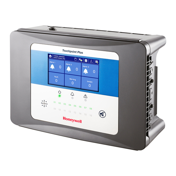
(see Ch.7.17 Monitoring TPPL via the Optional Web Interface). 7.1 User Interface General Local Accept / Reset Button Touchpoint Plus Controller User Interface The User Interface panel (shown above) has: • A colour Touch screen for normal system operation, maintenance and configuration •... -
Page 82: Touchscreen
There are only three passworded accounts: Administrator, Service and Operator, and their passwords must be carefully guarded. Lost passwords can only be replaced by someone higher which, in the case of the Administrator, will be a Honeywell representative. Password holders should be assigned to one access level only. -
Page 83: Menu Items And Access Levels
Note: Logged in users are automatically timed out after fifteen minutes of activity. For security reasons do not leave the Touchscreen unattended while logged in. Note: If user fails the password 10 times consecutively, Touchpoint Plus log-in is locked for all access levels. After 10 minutes, log-in becomes available. - Page 84 Language Sensor Catalogue Module Data SD Card MAN0984_Iss 4_01/19 Touchpoint Plus Pt. No. 3011M5001 Technical Handbook...
-
Page 85: Navigation Active Access Level Icons
Overwritten data is not recoverable. A further warning is given when data is being overwritten, The SD card icon on the front panel changes to yellow if the Touchpoint Plus is unable to save data or the SD card is being overwritten. -
Page 86: Checking The Capacity Of The Sd Card
6) Insert or replace the card in the SD card slot. 7) Note: the SD card is retained by a spring clip immediately above the card. Press the clip to remove or replace the card. MAN0984_Iss 4_01/19 Touchpoint Plus Pt. No. 3011M5001 Technical Handbook... -
Page 87: Normal Operation (Safety Functions)
Be careful with the mA output and relay setting as user can configure the setting of mA output and relay operation. Below table shows the recommendation of mA output and relay setting for safety function of Touchpoint Plus. One of either RLY1 or RLY2 in main board shall be configured to system inhibit relay State... -
Page 88: Operating Overview
• The system response time of Touchpoint Plus is 3 s. However, the gas response time of Touchpoint Plus will be increased more of input sensor's time of response. • Touchpoint Plus monitors the internal communication. In case of communication error detected, Touchpoint Plus will generate the communication fault in 5 s. - Page 89 Fault History Warning Filter Inhibit History Filter Information Warning History Filter Refresh Toggle View Filters only show during active events but you can use them to instantly filter multiple events for clarity. MAN0984_Iss 4_01/19 Touchpoint Plus Pt. No. 3011M5001 Technical Handbook...
-
Page 90: Navigating The Channel Detail Screens
Touchpoint Plus User Guide 7.7.3 Navigating the Channel Detail Screens. Touch an individual channel or item to display more details: Refer to Ch.15 Icon Glossary for further information. MAN0984_Iss 4_01/19 Touchpoint Plus Pt. No. 3011M5001 Technical Handbook... -
Page 91: Navigation Active Events And Filtering
Touchpoint Plus User Guide 7.7.4 Navigation Active Events and Filtering You can change the list type by touching a filter from one of the Tile views. Event data may be exported to the SD card by touching History>Export Event Note : In event view display, events are displayed in an order of priority: Alarm >... -
Page 92: Navigation Menu
Touchpoint Plus User Guide 7.7.5 Navigation Menu User must have the appropriate access level to enter Maintenance, Configuration and System Test options. Inactivity Timeout The user will be logged out after a period of inactivity. (Menu->Configuration->General->Timeout) Changes may not be saved. -
Page 93: Responding To Alarms
7.8 Responding to Alarms 7.8.1 Remote Reset and Acknowledge Switches Touchpoint Plus supports an optional remote Acknowledge or Reset switch which can be used to acknowledge or reset certain events. These switches do not require a user login. To prevent unauthorised activation, access should be restricted, for instance by use of a lockable switch. Refer to Figure 25. -
Page 94: Reset A Latched Alarm
Touchpoint Plus User Guide 7.8.4 Reset a Latched Alarm A latched alarm is one that cannot automatically reset itself when the triggering event has cleared. Note: Operator or higher access level is required A latched alarm can be reset in three ways: 1) By logging in and pressing the button for >3 seconds. -
Page 95: Resetting Latched Events
[Yes] 3) Or use a Remote Inhibit input (key-locking) switch. 4) Or set input channel gas sensor to inhibit mode so that Touchpoint Plus will receive respective current. 7.10.2 To Clear Inhibits: 1) Log in as Administrator or Service... -
Page 96: To Change Inhibit Timeouts
4) Touch a channel and the Channel detail (left below) screen will appear. Depending on access level, a number of options will be shown (see Ch.15 Icon Glossary for Icon names): MAN0984_Iss 4_01/19 Touchpoint Plus Pt. No. 3011M5001 Technical Handbook... - Page 97 Clear Inhibit. See Inhibit Service Normal Operation, Inhibit for more information. Shows the physical position of the I/O Channel location Viewer Module and channel (see pictures above). Viewer Scroll Left, Right, Up, Down. MAN0984_Iss 4_01/19 Touchpoint Plus Pt. No. 3011M5001 Technical Handbook...
-
Page 98: Viewing Output Channels
Touchpoint Plus User Guide 7.12 Viewing Output Channels From the Input screen, toggle the Home icon between Channel Tile>Channel Summary>Channel Output 1) From the Input screen, select Channel List or Channel Tile. 2) A list of all output channels is shown in order of channel ID. The channel ID, location tag and status are shown. -
Page 99: Viewing T H E Trend Graph
4) The trend graph will be displayed. Use the arrows to move backwards or forwards in time; use the X or [Cancel] to exit. Note: The Touchpoint Plus Trend / Plot will retain up to the latest 8 hours of data but will be cleared after a power reset. -
Page 100: Viewing And Exporting Event History
The event history for the complete system can be viewed in date order (latest first). The history can be filtered by Alarm, Fault, Inhibit, or Warning. Note: Touchpoint Plus does not adjust automatically for daylight savings time. So it will retain a backup of the earlier data if the clock is backdated (e.g. when ending daylight savings time). -
Page 101: Monitoring Tppl Via The Optional Web Interface
Safari • Other browsers may work but their performance may vary. Note: Contact Honeywell Support (refer to back page of this manual) if a browser security update causes performance issues. 7.17.1 Web Interface Configuration The Web Interface supports two concurrent web clients. Further users may connect, but performance may be degraded. -
Page 102: Web Interface Channel List View
Touchpoint Plus User Guide You can select how you monitor TPPL via the Web Interface menus by selecting from the menu: Web Interface Channel List View Web Interface Channel Summary View Web Interface Connection Failed Dialog MAN0984_Iss 4_01/19 Touchpoint Plus Pt. -
Page 103: Web Interface Navigation
Touchpoint Plus User Guide 7.17.2 Web Interface Navigation The Web Interface menu allows you to see and monitor the following information: • System Information • Event History • Trend / Plot (not IE8 or IE9) • Channel Information • Module Information •... -
Page 104: Chapter 8. Routine Maintenance And Scheduled Testing
Note: Input sensor's sensitivity reduces over time. Regular recalibration is required to make allowance for these changes. This slow change is monitored by Touchpoint Plus and is used to give the input sensor life expired warning or calibration fail when the sensitivity is < 50 % of the first calibration. -
Page 105: Routine Testing
5) Check the alarm outputs are visible / audible and turn them off when satisfied. 6) Touch [Finish] when the tests are completed and all selections will automatically turn off. CAUTION Ensure that the system is returned to normal operation once testing is complete. MAN0984_Iss 4_01/19 Touchpoint Plus Pt. No. 3011M5001 Technical Handbook... -
Page 106: Exercising The Relays
4) Touch the All radio button and check the mA output value; touch the mA box to change it. For single channels touch the Single Channel number box and then scroll through the list and touch the required channel followed by [Select]. MAN0984_Iss 4_01/19 Touchpoint Plus Pt. No. 3011M5001 Technical Handbook... -
Page 107: Calibrating Mv Input Channels
1) Login as Administrator or Service. 2) Touch and select a mV input channel. Menu>Maintenance>Adjust mV Baseline 3) Touch . Touch the channel to be calibrated, followed by [Select]: Menu>Maintenance>Gas Calibration MAN0984_Iss 4_01/19 Touchpoint Plus Pt. No. 3011M5001 Technical Handbook... - Page 108 Touchpoint Plus will exit the calibration menu no matter of current gas reading in calibration mode in 45 s after purging gas step. User may see gas alarm if user cannot ensure the gas reading value of Touchpoint Plus lower than alarm level in purging step.
-
Page 109: Periodic Scheduled Testing
Field Inputs Test this tests all input channel devices without affecting any outputs. • Cause and Effect Test this test forces the Touchpoint Plus input channels to known states to test that the correct relay output channels are activated. WARNING The Touchpoint Plus system is not operational while in Test Mode, and all field device inputs will be ignored. -
Page 110: Field Inputs Test
8.3.3 Cause and Effect Test See Cautions above. During this test, all field device inputs will be ignored by the Touchpoint Plus system. The Cause and Effect matrix will be evaluated based on simulated input states and outputs will be generated. -
Page 111: Lcd, Led And Buzzer Test
For testing reaction and/or response time, refer to the real-time gas reading value shown on the display during the gas calibration or refer to the logging data of the mA output. MAN0984_Iss 4_01/19 Touchpoint Plus Pt. No. 3011M5001 Technical Handbook... -
Page 112: Chapter 9. Repairs, Replacements And Upgrades
-up battery installed). 10) Close and secure the enclosure door. 11) Switch on the Touchpoint Plus and wait for the system to stabilise. 12) Login as an Administrator or Service. 13) Touch Menu>Configuration>Module Control panel 14) Touch [Refresh] to confirm the modules were removed correctly. -
Page 113: How To Replace A Faulty I/O Module
WARNING If the relays are switching mains voltages, hazardous live terminals may be present within the Relay Output Module even if the Touchpoint Plus system is isolated. Isolate hazardous voltages before proceeding. ANTI STATIC PRECAUTIONS Antistatic Precautions are required to prevent damage to electronic components Note: The new module must be the same type and same or higher mod state as the module to be removed. -
Page 114: How To Add A New I/O Module
Repairs, Replacements and Upgrades 9.3 How to Add a New I/O Module The Touchpoint Plus system can easily be expanded by adding additional I/O modules. Refer to Ch.3.3.1 and Ch.3.3.2 for full populated I/O modules ANTI STATIC PRECAUTIONS Antistatic Precautions are required to prevent severe damage to electronic components. -
Page 115: How To Update The Sensor Catalogue
9.4 How to Update the Sensor Catalogue From time to time, Honeywell will release new or updated versions of the sensor catalogue. It is not necessary to update the catalogue every time, and it can wait until you want to install a type of sensor not previously listed. -
Page 116: How To Backup / Restore The System Configuration
Repairs, Replacements and Upgrades 9.5 How to Backup / Restore the System Configuration CAUTION You should always take a new back up of the Touchpoint Plus system configuration after changes are made and confirmed. 9.5.1 To Create a Backup File Note: The Touchpoint Plus system must be turned off to change the SD card so alternative safety arrangements should be put in place prior to starting this procedure. -
Page 117: To Restore The Configuration From A Backup File
Note: You cannot restore configuration files if the I/O module configuration has changed since the last backup. 9.5.2 To Restore the Configuration From a Backup File Note: The Touchpoint Plus system must be turned off to change the SD card so alternative safety arrangements should be put in place prior to starting this procedure. -
Page 118: How To Update Firmware
16) See and touch the SD Card Icon to confirm it has sufficient space to record events. 9.6 How to Update Firmware Firmware and software updates should normally be carried out only by a Honeywell trained Engineer or a qualified Engineer trained in accordance with this Technical Manual. -
Page 119: How To Update The Firmware
Do not Power Off while the Firmware update is in progress as this may cause data corruption and render the system inoperable. To update the Firmware: 1) Contact your local representative or Honeywell Analytics Support and ask for a copy of the latest download. 2) Download the required Firmware \\FW\*.bin onto any device that can copy to a standard SD Card. -
Page 120: Back Up Battery Maintenance
Repairs, Replacements and Upgrades 9.7 Back up Battery Maintenance DANGER Replace the battery pack only with Honeywell Analytics part no. TPPLSIBB and the PCB CMOS battery only with battery type CR2032. Use of other batteries may present a risk of fire or explosion. -
Page 121: Return To Factory Default Settings
9.8 Return to Factory Default Settings If required, the system Administrator or a Honeywell Service Technician can return the TPPL Controller to its Factory Default settings. Passwords are not changed when resetting to Factory Default settings so this procedure cannot be used to restore forgotten passwords to the default password. -
Page 122: Chapter 10. Troubleshooting
Ch.18 Event Codes before power-cycling the TPPL as they may not be reproducible following a system reboot. Contact Honeywell Analytics Technical Support if an error appears repeatedly, if it cannot be cleared, or if it is not listed in Ch.18. Event Codes. -
Page 123: Chapter 11. Technical Specifications
*Voltage drop at ambient temperature Remote Terminals Optional remote acknowledge, reset and inhibit 4.4 W for User interface module and Main Module (Max 33.2W @ Module Power Consumption Audio/Visual Alarm device connected) MAN0984_Iss 4_01/19 Touchpoint Plus Pt. No. 3011M5001 Technical Handbook... -
Page 124: I/O Modules
Max 0.3 W (Excludes power to field device) Supply voltage Vs (18 32 VDC) *1.8 VDC (max) Field Device Power Supply Vmax ( ) *Voltage drop in Touchpoint Plus Field Device Power Supply Power max 20 W (single channel) Field Device Power Supply Power max... -
Page 125: Ma Output Module
DC Input Voltage Range ( ) Input Frequency Range (~) AC 50 60 Hz ± 6 % DC 24 V Output Voltage ( ) Dimension 199 x 98 x 38mm (L x W x H) MAN0984_Iss 4_01/19 Touchpoint Plus Pt. No. 3011M5001 Technical Handbook... -
Page 126: Backup Battery
W 423 x D 325 x H 16.5 mm 1.5 Kg (approx.) Enclosure Weight 8.5 Kg (approx.) Dimension 426 mm x 300 mm x 156 mm (16.9 ins x 11.8 ins x 6.2 ins) MAN0984_Iss 4_01/19 Touchpoint Plus Pt. No. 3011M5001 Technical Handbook... -
Page 127: Chapter 12. Certifications
Certifications Chapter 12. 12.1 EU Declaration of Conformity A full EC declaration of conformity is available on either original hardcopy or electronic file (Honeywell Analytics website). This document lists the European Standards with which Touchpoint Plus complies. WARNING Only the combustible gas detection portion of this instrument has been assessed for performance in accordance with the ATEX Directive. -
Page 128: European Performance Approval (Dekra Testing And Certification Gmbh) For Systems
12) Transmission errors between modules cause a fault after 5 s at the latest. 13) Do not use Touchpoint Plus with 4-20 mA transmitters which may give indications within their measuring range at gas concentrations above full scale. -
Page 129: Special Conditions For Use When Used For Measurement Of Toxic Gases Or Oxygen129
Do not set the parameter "Upper deadband" to a value above 0.5 %Vol. 12) Operation according to EN 45544-2: Touchpoint Plus is suitable for use with 4-20 mA transmitters where the output at the limit value is between 4.96 mA and 12 mA. -
Page 130: Chapter 13. Replacement Parts And Optional Extras
Replacement Parts and Optional Extras Chapter 13. The following replacement parts and optional extras are available to order, but Honeywell Analytics cannot accept responsibility for their incorrect handling, storage, fitment or use. All Honeywell supplied replacement parts are covered by the standard Honeywell warranty service. -
Page 131: Publications
Replacement Parts and Optional Extras 13.2 Publications These publications are available to download as printable .pdfs from the Honeywell Analytics website. Description Language Part Number Chinese (Simplified) 3011M5029 Netherlands 3011M5030 English (GB) 3011M5000 French (Canada) 3011M5031 French (France) 3011M5032 German... - Page 132 French (France) 3011M5046 German 3011M5047 Italian 3011M5048 Japanese 3011M5049 TPPL User Guide Korean 3011M5050 Portuguese (Brazil) 3011M5051 Portuguese (Portugal) 3011M5052 Russian 3011M5053 Spanish (Mexico) 3011M5054 Spanish (Spain) 3011M5055 Swedish 3011M5056 3011M5057 MAN0984_Iss 4_01/19 Touchpoint Plus Pt. No. 3011M5001 Technical Handbook...
-
Page 133: Chapter 14. Tppl Configuration Code
18 32 V mA/mV N = No mA N = No Relay Inputs Output D8 = Dual 8ch mA/mV Inputs Code: TPPL (Example) Table 16. TPPL Configuration P/N Code Chart (example) MAN0984_Iss 4_01/19 Touchpoint Plus Pt. No. 3011M5001 Technical Handbook... -
Page 134: Chapter 15. Icon Glossary
Alarm Pop Up Inhibit Filter Error Pop Up Warning Filter Fault Pop Up Filter Information Inhibit Pop Up Filter Refresh Warning Pop Up Battery Warning Battery Critical Gas Calibration Power Off MAN0984_Iss 4_01/19 Touchpoint Plus Pt. No. 3011M5001 Technical Handbook... -
Page 135: Chapter 16. Compatible Sensors
Refer to the respective sensor data sheets for more details. Table 17. TPPL Gas Detectors Note: Touchpoint Plus is not currently approved as a fire or flame detection system, but this chapter will be updated when its flammables capability is fully tested and certified. Note: Customer-supplied 3 Party sensors may be used, but Honeywell is unable to support them or guarantee their performance. -
Page 136: Chapter 17. Configurable Parameter Reference Guide
Range Ratio, %LEL x M, ppm x m, EG x m, %Vol x m, LEL.m, LEL%.m, %V/V, mA, kppm, oC, oF, %RH Target Gas Digit Numbers of decimal point mA Input MAN0984_Iss 4_01/19 Touchpoint Plus Pt. No. 3011M5001 Technical Handbook... - Page 137 Input Disable/Enable Disable Alarm 3 Threshold Alarm 3 threshold concentration mA Input Rising/Falling Rising Trigger 2%FSD ~ Alarm 3 Level Alarm 3 threshold concentration mA Input 60% of Full range 100%FSD MAN0984_Iss 4_01/19 Touchpoint Plus Pt. No. 3011M5001 Technical Handbook...
- Page 138 2.1 mA sensor if min/max is set to zero, mA minimum fault current from mA output Signal Fault Min. mA Input 0~24 0.0 mA input board will not detect sensor fault condition. MAN0984_Iss 4_01/19 Touchpoint Plus Pt. No. 3011M5001 Technical Handbook...
- Page 139 Channel Tag Channel description tag (25 characters) mV Input Character 50 chars Range Alphanumeric Write available when: Detector Name 20 characters mV Input Character 40 chars Detector Name- User Range Detector MAN0984_Iss 4_01/19 Touchpoint Plus Pt. No. 3011M5001 Technical Handbook...
- Page 140 Disable/Enable Disable Alarm 1 Threshold Alarm 1 trigger option (Rising or Falling) mV Input Rising/Falling Rising Trigger Alarm 1 Level Alarm 1 threshold concentration mV Input 2~100%FS 20% of Full range MAN0984_Iss 4_01/19 Touchpoint Plus Pt. No. 3011M5001 Technical Handbook...
- Page 141 20 ~ 100 %FSD 50% of Full range Conc. Bridge Current Different value Depend on Detector mV Input 100~300mA 200 mA Unit Correction Correction factor for other target gas mV Input Factor MAN0984_Iss 4_01/19 Touchpoint Plus Pt. No. 3011M5001 Technical Handbook...
- Page 142 Relay Activate Delay Time Delay time to activate the relay Output 0~3000 0 sec Relay Relay Hold Time Delay time to de-activate the relay Output 0~3000 0 sec MAN0984_Iss 4_01/19 Touchpoint Plus Pt. No. 3011M5001 Technical Handbook...
- Page 143 Relay Check/not Reduction on inhibit 0: reduction, 1: no reduction Output check Check Channel Enable Channel Enable/Disable TRUE/FALSE Disable Output Channel ID will be Channel Number Number 1~16 Output automatically assigned MAN0984_Iss 4_01/19 Touchpoint Plus Pt. No. 3011M5001 Technical Handbook...
- Page 144 Static Gateway Address System Character 192.168.0.1 xxx.xxx.xxx.xxx Address Range xx-xx-xx-xx-xx-xx. Writing is MAC Address max 20 characters System only possible during production. Operator Password Password for Access Level Operator System 35 chars TPPL MAN0984_Iss 4_01/19 Touchpoint Plus Pt. No. 3011M5001 Technical Handbook...
- Page 145 System 0~600 0: Disable, second Gas log Threshold Gas log Threshold System 0.1~2.0 0 means that gas log will be stored every log interval. Buzzer Enable Buzzer enable/disable System Enable/Disable Disable MAN0984_Iss 4_01/19 Touchpoint Plus Pt. No. 3011M5001 Technical Handbook...
- Page 146 Language Setting Select a language to display screen System English(0) ESPANOL, RUSSIAN, PORTUGUESE 0 HH:MM:SS DD/MM/YYYY 1 HH:MM:SS DD/MM/YY Time Format Time, date format System 2 YY/MM/DD HH:MM:SS 3 HH:MM:SS MM/DD/YY MAN0984_Iss 4_01/19 Touchpoint Plus Pt. No. 3011M5001 Technical Handbook...
-
Page 147: Chapter 18. Event Codes
4:Relay, 5:mA output, [B/D Type] 7:Modbus, 7:Extension power Code Sensor circuit fault 0: Gain setting error, Fault Sensor circuit fault IO board CH: xx, Code: xxx 1: signal conditioning circuit error MAN0984_Iss 4_01/19 Touchpoint Plus Pt. No. 3011M5001 Technical Handbook... - Page 148 Remote fault informed by detector Detector In Fault Input, 3 : mV input, Fault IO board (depending on fault signal range) CH: xx, [B/D Type] 4:Relay, 5:mA output, 7:Modbus, 7:Extension power MAN0984_Iss 4_01/19 Touchpoint Plus Pt. No. 3011M5001 Technical Handbook...
- Page 149 Calibration is Calibration interval - Warning Calibration is due soon Main Board overdue days passed after CH: xx, Due: xxxx successful calibration Date/Time not set Warning Time/date not set UI Board [Date/Time] MAN0984_Iss 4_01/19 Touchpoint Plus Pt. No. 3011M5001 Technical Handbook...
- Page 150 0:Main, 1:UI, 2:mA Input, 3: mV input, Replaced IO board 4:Relay, 5:mA output, Info Replaced IO board UI Board [B/D Type], Slot: xx-x 7:Modbus, 7:Extension power Slot Refer to Note 1 MAN0984_Iss 4_01/19 Touchpoint Plus Pt. No. 3011M5001 Technical Handbook...
- Page 151 Info mA Output Configuration Changed Main Board output channel CH: xx Button type Button Press – Acknowledge alarms and Pressed Ack button Info Main Board 0:On Board, faults [button type] 1:Remote MAN0984_Iss 4_01/19 Touchpoint Plus Pt. No. 3011M5001 Technical Handbook...
- Page 152 UI Board Changed system label mA Input calibration Info mA Input calibration successful UI Board passed Ch: xxx mA Input calibration Info mA Input calibration failed UI Board failed CH: xx MAN0984_Iss 4_01/19 Touchpoint Plus Pt. No. 3011M5001 Technical Handbook...
- Page 153 Input, 3 : mV input, Info Firmware Update failed UI Board [B/D Type], Ver: x.x.x 4:Relay, 5:mA output, 7:Modbus, 7:Extension power Catalog Updated Info Updated sensor catalogue UI board Ver: xxxx MAN0984_Iss 4_01/19 Touchpoint Plus Pt. No. 3011M5001 Technical Handbook...
- Page 154 0:Main, 1:UI, 2:mA Failed in module data Input, 3 : mV input, Info Failed in module data update UI Board update 4:Relay, 5:mA output, [B/D type], Ver: xxxx 7:Modbus, 7:Extension power MAN0984_Iss 4_01/19 Touchpoint Plus Pt. No. 3011M5001 Technical Handbook...
-
Page 155: Chapter 19. List Of Figures
Wall and Plate Mounting Points Switched Mode Power Supply (SMPS) Connections Connections for DC 24 V Supply Connecting the Touchpoint Plus and Optional Expansion Unit to a Mains Supply 34 Basic Unit Main Module Connections Expansion Unit Main Module Connections... - Page 156 List of Figures Information Menu Configuration Menu Maintenance Menu System Test Menu Touchpoint Plus Controller User Interface Web Interface Channel List View Web Interface Channel Summary View Web Interface Connection Failed Dialog Web Interface Information Menu Showing Event History Battery On/Off Switch and Battery Connector...
-
Page 157: Chapter 20. List Of Tables
Home Screen Menu Icons Table 13. Home Screen Menu Icons Table 14. User / Component Matrix Table 15. Home Screen Icons Table 16. TPPL Configuration P/N Code Chart (example) Table 17. TPPL Gas Detectors MAN0984_Iss 4_01/19 Touchpoint Plus Pt. No. 3011M5001 Technical Handbook... - Page 158 This publication is not intended to form the basis of a contract. Issue 4 EN 01/2019 H_MAN0984_EMEA 3011M5001 HAA190006 9 Honeywell Analytics...