Samsung DCS Installation Manual
Hide thumbs
Also See for DCS:
- Programming manual (410 pages) ,
- Technical manual (287 pages) ,
- Manual (58 pages)
Table of Contents
Advertisement
Quick Links
Advertisement
Table of Contents

Related Manuals for Samsung DCS


Summary of Contents for Samsung DCS
- Page 1 SAMSUNG INSTALLATION MANUAL...
- Page 2 Publication Information Samsung Telecoms reserves the right without prior notice to revise information in this publication for any reason. Samsung Telecoms also reserves the right without prior notice to make changes in design or components of equipment as engineering and manufacturing may warrant.
- Page 3 259 Gongdan-Dong, Gumi-City Kyungbuk, Korea, 730-030 (factory name, address) declare under our sole responsibility that the product Digital Keyphone System "DCS" to which this declaration relates is in conformity with RTTE Directive 1999/5/EC ( Annex II ) Low Voltage Directive 73/23/EEC...
- Page 4 Intended Use This telephone system is intended to provide the user with voice communication between the system extensions and connection to the public switched telephone network by digital or analogue links. The telephone system may be provided with the ability to communicate with local computer net- works to provide CTI functions and features.
-
Page 5: Table Of Contents
5.6 Basic Rate (BRIN) ..............................31 Part 6. Connecting Station Equipment ........38 6.1 Safety Precautions..............................38 6.2 DCS Keyset................................38 6.3 Add-On Module ..............................38 6.4 Single Line Telephone ............................38 6.5 Doorphone and Door Lock Release ........................39... - Page 6 Contents Part 7. Connecting Optional Equipment ........ 46 7.1 Music On Hold/Background Music ........................46 7.2 External Paging............................... 46 7.3 Common Bell ................................47 7.4 Ring Over Page ............................... 47 7.5 Loud Ringer ................................47 7.6 SMDR ..................................47 7.7 PC Programming..............................48 7.8 Remote Programming .............................
-
Page 7: Part 1. Site Requirements
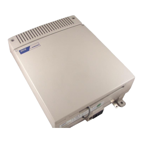
Installation March 2001 Part 1. Site Requirements When planning the installation of the DCS system, choose a site that meets the following require- ments: • Select a location for the key service unit (KSU) that has enough space for easy installation and has adequate lighting (Figure 1–1). - Page 8 Samsung DCS Part 1 Installation March 2001...
-
Page 9: Part 2. Installing Basic Ksu And Expansion Cabinets
Samsung DCS Part 2 Installation March 2001 Part 2. Installing Basic KSU and Expansion Cabinets 2.1 Unpacking and Inspection After unpacking the KSU and expansion cabinets, inspect for signs of physical damage. If any dam- age is detected, do not attempt to install. Contact your dealer for advice. -
Page 10: Multiple Cabinet Installation
NOTE: Failure to set the battery switch will prevent the system from saving any customer-programmed data. 6. Before beginning programming, reset the database by clearing memory using MMC 811 (see the Samsung DCS Combined Programming Manual for details). 2.3 Multiple Cabinet Installation 1. -
Page 11: Grounding The Ksu
NOTE: To activate the new cabinet, open system programming and use MMC 806 to reinstall slot 7 of the basic KSU (see the Samsung DCS Combined Programming Manual for details). The data pertaining to the card removed from slot 7 will be lost and must be re-entered for its new position. - Page 12 Samsung DCS Part 2 Installation March 2001...
- Page 13 Samsung DCS Part 2 Installation March 2001...
- Page 15 Samsung DCS Part 2 Installation March 2001...
- Page 17 Samsung DCS Part 2 Installation March 2001...
- Page 18 Samsung DCS Part 2 Installation March 2001...
-
Page 19: Part 3. Installing Printed Circuit Cards
Samsung DCS Part 3 Installation March 2001 Part 3. Installing Printed Circuit Cards Unpack and inspect each card before installing. Check for signs of physical damage. If any damage is detected, do not attempt to install. Contact your dealer for advice. -
Page 20: 8Sli Card
Samsung DCS Part 3 Installation March 2001 3.7 8SLI Card This card (Figure 3–7) has no selectable options. Insert as many 8SLI cards as are needed into uni- versal slots 1 to 7. This card does not have its own DTMF receivers; therefore it uses the DSP engine on the CPM (KSU central processor) as a DTMF receiver. - Page 22 Samsung DCS Part 3 Installation March 2001...
- Page 23 Samsung DCS Part 3 Installation March 2001...
- Page 24 Samsung DCS Part 3 Installation March 2001...
- Page 25 Samsung DCS Part 3 Installation March 2001...
- Page 26 Samsung DCS Part 3 Installation March 2001...
- Page 27 Samsung DCS Part 3 Installation March 2001...
- Page 28 Samsung DCS Part 3 Installation March 2001...
- Page 29 Samsung DCS Part 3 Installation March 2001...
- Page 30 Samsung DCS Part 3 Installation March 2001...
- Page 31 Samsung DCS Part 3 Installation March 2001...
- Page 32 Samsung DCS Part 3 Installation March 2001...
- Page 33 Samsung DCS Part 3 Installation March 2001...
-
Page 34: Part 4. Power Up Procedures
Part 4. Power Up Procedures Where you are instructed to run an MMC program while following these procedures, refer to the Samsung DCS Combined Programming Manual. 4.1 Connecting Power to the System During the initial installation, it is best to verify proper system operation before plugging in any am- phenol-type cables to the MDF. -
Page 35: Rom Card Indications
Samsung DCS Part 4 Installation March 2001 The LED on the ROM pack will light steady and then start flashing to confirm the presence of power and that the processor is running. The LEDs on the EXPN cards will light steady red to indicate the presence of power and that the local processor is running. -
Page 36: Default Trunk And Station Numbering
Samsung DCS Part 4 Installation March 2001 Remove the test cable and plug in all amphenol-type cables to the MDF. It is recommended that the system is now ‘defaulted’ (reset) using MMC 811. You can then proceed with the rest of the installa- tion. -
Page 37: Part 5. Connecting Pstn Circuits
Connect the PRI card to the PSTN-supplied network terminating box using the RJ-45 cable supplied. 5.6 Basic Rate (BRIN) Using two pair twisted 0.5mm or 0.8mm jumper wire, cross-connect BRI circuits to the DCS BRIN trunk port of your choice (Figure 5-6). - Page 38 Samsung DCS Part 5 Installation March 2001...
- Page 39 Samsung DCS Part 5 Installation March 2001...
- Page 40 Samsung DCS Part 5 Installation March 2001...
- Page 41 Samsung DCS Part 5 Installation March 2001...
- Page 42 Samsung DCS Part 5 Installation March 2001...
- Page 43 Samsung DCS Part 5 Installation March 2001...
-
Page 44: Part 6. Connecting Station Equipment
(Figure 6–1). NOTE: Because the DCS is a self-configuring system, if you connect a 12-button keyset to a DLI port that previously had a 24-button keyset installed, the existing data will be rewritten with 12-button keyset default data (see MMC 722). This can be avoided if you first save the keyset data using MMC 721. -
Page 45: Doorphone And Door Lock Release
DPIM to the door lock mechanism (Figure 6–5). Use MMC 501 to program the duration of the contact closure as required. (See the Samsung DCS Keyset User Guide for details of door lock release operation.) The door release contacts on the DPIM are to be used for low-voltage relay control only. - Page 46 Samsung DCS Part 6 Installation March 2001...
- Page 47 Samsung DCS Part 6 Installation March 2001...
- Page 48 Samsung DCS Part 6 Installation March 2001...
- Page 49 Samsung DCS Part 6 Installation March 2001...
- Page 50 Samsung DCS Part 6 Installation March 2001...
- Page 51 Samsung DCS Part 6 Installation March 2001...
-
Page 52: Part 7. Connecting Optional Equipment
IMPORTANT NOTICE: In accordance with UK law, a license may be required from the Performing Rights Society or other similar organisation if copyrighted music is transmit- ted through the Music On Hold feature. Samsung Telecoms hereby disclaims any liabil- ity arising out of failure to obtain such a license. -
Page 53: Common Bell
Samsung DCS Part 7 Installation March 2001 7.3 Common Bell A customer-provided loud ringing device can be controlled using the dry contact pair on the MISC card (Figure 7–3). Using MMC 204, programming allows for interrupted or con- tinuous operation of the contacts. The interrupted selection follows the C.O. ring cadence. -
Page 54: Pc Programming
Samsung DCS Part 7 Installation March 2001 Use MMC 725 to set SMDR print options and use MMCs 804 and 311 to set the transmis- sion parameters for the SIM port. NOTE: The SIM has a minimum transmission speed of 1200 baud. -
Page 55: Voice Mail/Auto Attendant
Samsung DCS Part 7 Installation March 2001 7.10 Voice Mail/Auto Attendant System operation provides special programming and hardware for use with a customer- provided voice mail/auto attendant system. All single line telephones on the SLI card provide a disconnect signal required for VM/AA operation. - Page 56 Samsung DCS Part 7 Installation March 2001...
- Page 57 Samsung DCS Part 7 Installation March 2001...
- Page 58 Samsung DCS Part 7 Installation March 2001...
- Page 59 Samsung DCS Part 7 Installation March 2001...
- Page 60 Samsung DCS Part 7 Installation March 2001...
- Page 61 Samsung DCS Part 7 Installation March 2001...
- Page 62 Samsung DCS Part 7 Installation March 2001...
- Page 63 Samsung DCS Part 7 Installation March 2001...
- Page 64 Samsung DCS Part 7 Installation March 2001...
-
Page 65: Part 8. Changing Software
8.1 Changing System Software The system software on the DCS is contained in the ROM card. This card is fitted with a removable door which must be removed to allow the software to be changed (Figure 8–1). The four EPROM chips are located at one end of the PCB and are labelled U11 (EVEN 1), U12 (ODD 1), U13 (EVEN 2) and U14 (ODD 2) (Figure 8–2). - Page 66 Samsung DCS Part 8 Installation March 2001...
- Page 67 Samsung DCS Part 8 Installation March 2001...
- Page 68 Samsung DCS Part 8 Installation March 2001...
- Page 69 Samsung DCS Part 8 Installation March 2001...
-
Page 70: Part 9. Installing Keysets
(Figures 9-2 and 9-3). 9.2 Wall-Mounting a Keyset DCS keysets come equipped with a reversible base wedge as standard. To wall-mount a keyset, re- move the wedge from the keyset, turn it through 180 degrees and reattach it to the keyset (Figure 9–... - Page 71 Samsung DCS Part 9 Installation March 2001...
- Page 72 Samsung DCS Part 9 Installation March 2001...
- Page 74 Samsung DCS Part 9 Installation March 2001...
- Page 75 Samsung Telecoms (U.K.) Limited Brookside Business Park, Greengate, Middleton, Manchester M24 1GS Tel: 0161 655 1100 Fax: 0161 655 1166...