Advertisement
APPLICATION
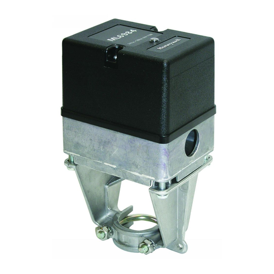
The ML6984 and ML7984 are self-contained,
self-adjusting, linear motorized valves that mount directly
onto V5011 two-way and V5013 three-way globe valves,
providing linear travel (stem lift) between 13 mm (1/2")
and 25mm (1").
ML6984 is for use with low voltage SPDT Series
20 (on-off) and Series 60 (floating) electro-mechanical
or electronic controllers. ML7984 is for use with Series
70 2-10 Vdc, 4-20 mA, electronic series 90, 135 Ω and
modulating controllers.
PCY 06/99
© Honeywell Ltd. 1999 Printed in Canada
ML6984, ML7984 Series 4000
Direct Coupled Valve Actuators
FEATURES
• Self-contained, motorized valve linkage
• NEMA 3R cover for outdoor installation
• Linkage self-adjusts to valve stroke from 13 mm
(1/2") to 25 mm (1")
• DIP switches select various input configurations
• LED status indication
• Floating models compatible with 3-wire control
systems
• Strong valve seat closing force 710 N (160 lbs.)
• Electronic current sensing provides nternal
protection and positive fully closing force
• Compact size for easy installation in confined
area
• Allows the use of one common transformer power
supply for multiple actuators and controllers
• One device for either 24 V ac or 28 Vdc power
supply application
• Field-addable auxiliary switches available
• Field-addable position feedback option available
Contents
Specifications............................................................2
Order information..................................................... 2
Installation................................................................ 3
Wiring Schematics....................................................4
Operation ................................................................11
Checkout.................................................................12
Troubleshooting ......................................................13
PRODUCT DATA
95C-10939
Advertisement

Related Manuals for Honeywell 4000 Series


Summary of Contents for Honeywell 4000 Series
-
Page 1: Table Of Contents
ML7984 is for use with Series 70 2-10 Vdc, 4-20 mA, electronic series 90, 135 Ω and modulating controllers. Contents Specifications............2 Order information............. 2 Installation..............3 Wiring Schematics............4 Operation ..............11 Checkout..............12 Troubleshooting ............13 PCY 06/99 © Honeywell Ltd. 1999 Printed in Canada 95C-10939... -
Page 2: Specifications
If you have additional questions, need further information, or would like to comment on our products or services, please write or phone: 1. Your local Honeywell Home and Building Control Sales office (Check white pages of your phone directory). 2. Honeywell Customer Care... -
Page 3: Installation
The valves are to be installed by skilled personnel and in strict accordance with the installation instructions and local regulations. Honeywell assumes no responsibility for dam- ages or injuries resulting from non-compliance with installa- tion instructions or standard good practice when mounting, operating, or maintaining the valves, even if not expicitly mentioned in the installation instructions. - Page 4 ML6984, ML7984 DIRECT COUPLED VALVE ACTUATORS 5. Remove the plastic cover from the ML6984 by loosening the two screws located on the top (Note: These screws are captive. Rotate three complete revolutions to remove cover ). Drop either Slot Headed or Allen Hex type of set screw (both are included in the plastic bag ) into the top of For proper valve operation, valve stem must be threaded the shaft, slotted/ Hexed side up.
-
Page 5: Operation
ML6984 Wiring Wiring ML_984 actuators are designed to operate from a Safety Extra Low Voltage, Class II power source. A 7/8” wiring hole is provided for attaching flexible conduit where required by local codes. When installing outdoors, weatherproof conduit fittings approved for outdoor and wet locations must be used. Electrical Shock or Equipment Damage Hazard. - Page 6 ML7984 Wiring SIGNAL 3 ML7984 SIGNAL SOURCE 3 ML7984 SOURCE 3 ML7984 2 3 ML7984 2 24 Vac 24 Vac 28 Vdc ML7984 28 Vdc (SLAVE) 3 ML7984 2 FIG. 8 — ML7984 WIRING WITH 10 FIG. 9 — ML7984 WIRING WITH 20mA VDC ANALOG CONTROL SIGNAL ANALOG CONTROL SIGNAL FUNCTION...
- Page 7 ML7984 Wiring FIG. 10 — ML7984 WIRING WITH 135Ω (SLIDEWIRE) CONTROLLERS MODULATING SIGNAL ML7984 ML7984 SOURCE LIMIT 24 Vac SIGNAL ML7984 ML7984 SOURCE 28 Vdc 24 Vac 24 Vac ML7984 ML7984 28 Vdc 28 Vdc 24 Vac 28 Vdc FIG. 10B — ML7984 WITH INDIVIDUAL FIG.
- Page 8 ML7984 Wiring FIG. 11 — ML7984 WIRING WITH ELECTRONIC SERIES 90 “SUPERMOD” CONTROLLERS ELECTRONIC ML7984 ML7984 SERIES 90 ELECTRONIC (W973, T775, SERIES 90 H775, W7100) (W973, T775, H775, W7100) 24 Vac NOTE: ML7984 ML7984 Polarity sensitive, 28 Vdc check connections W to R, R to W 24 Vac 24 Vac...
- Page 9 ML7984 Wiring ML7984A3xxx ML7984A3xxx ML7984A3xxx New Master Slave Slave R1=12 KΩ WWWW R2=3 KΩ NOTE: *Previously clipped resistor Turn power off before setting the DIP switches Fig. 12 Wiring for replacing the MASTER motor in 4-20 mA multiple-actuator application. (Use Resistor Kit part # 272822) ML7984A3xxx ML7984A3xxx ML7984A3xxx...
- Page 10 ML6984, ML7984 DIRECT COUPLED VALVE ACTUATORS Operation 1. Disconnect power supply before beginning installation Each time actuator terminals T5-T6 are (re)powered, the to prevent electrical shock and equipment damage. microprocessor will cycle the valve through a full stroke 2. All wiring must comply with applicable local electrical to calibrate its position.
-
Page 11: Checkout
ML6984, ML7984 DIRECT COUPLED VALVE ACTUATORS ML7984 TO REPLACE ML784 or ML984: 3. Make sure the Configuration DIPswitches are set correctly. 1. The old ML784 or ML984 actuators cannot be used 4. With 24Vac or 28Vdc power source connected to T5 with new ML7984 valve actuators in the same circuitry, and T6, actuator operation can be verified by unless the old models are each powered by their own... -
Page 12: Troubleshooting
ML6984, ML7984 DIRECT COUPLED VALVE ACTUATORS Troubleshooting Guide for ML Valve Actuator SYMPTOM POSSIBLE CAUSES ACTIONS Valve leaks or will not *Wrong actuator used and/or system *Check valve close-off rating close off fully. pressure too high *Check voltage at actuator terminals *Actuator not properly installed *Ensure valve stem is fully threaded into brass drive shaft and locked in place with the set...