Makita Makstar DC18SD Technical Information
Hide thumbs
Also See for Makstar DC18SD:
- Manual (32 pages) ,
- Instruction manual (8 pages) ,
- Quick start manual (8 pages)
Advertisement
Quick Links
T
ECHNICAL INFORMATION
Models No.
Description
C
ONCEPT AND MAIN APPLICATIONS
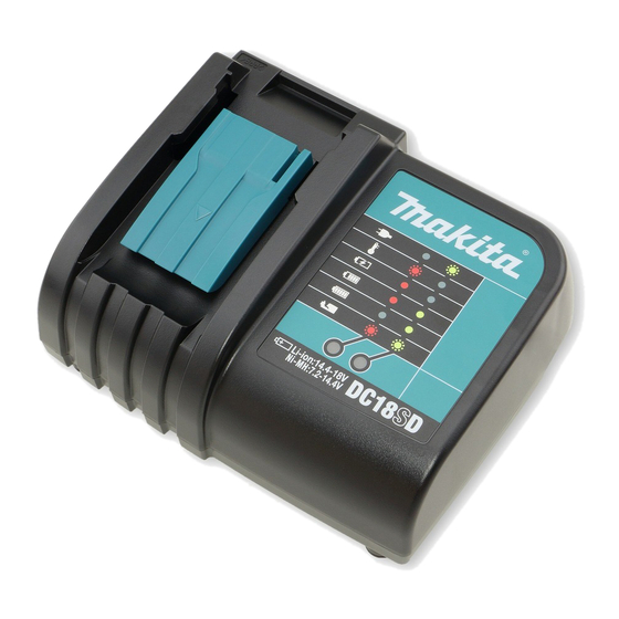
Cost-effective charger DC18SD has been launched for worldwide owners
of Makita slide-on type 7.2-18V Li-ion and Ni-MH batteries.
1.5 Ah Li-ion Battery can be charged in 30 minutes. (3.0Ah: 60 minutes)
Innovative computer controlled charging system realized most suitable
charge by making the digital communication between charger and battery.
See detailed information as follows.
This charger contains trickle charging function.
S
pecification
Voltage (V)
110-120
220-240
Output voltage : V
Output current : A
Double Insulation
Power Supply Cord: m ( ft )
Net weight: Kg (lbs)
Charging time
Approx. 30 min.
Approx. 60 min.
Approx. 40 min.
Approx. 70 min.
Note: The above figures about charging time may differ from condition to condition on batteries' temperature
or room temperature.
DC18SD
Charger
Current (A)
Cycle (Hz)
50 - 60
50 - 60
Cell
Capacity: Ah
1.5
Li-ion
3.0
2.0
Ni-MH
3.3
Continuous Rating (W)
Input
65
65
DC 7.2 - 18
DC 2.6
No
2.0 (6.6)
0.7 (1.5)
Voltage: V
Battery
14.4
BL1415
18
BL1815
14.4
BH1430 / A
18
BH1830
9.6
BH9020 / A
12
BH1220 / C
14.4
BH1420
BH9033
9.6
BH9033A
BH1233
12
BH1233C
14.4
BH1433
PRODUCT
H
L
Dimensions: mm (")
Length (L)
151 (5-15/16)
Width (W)
183 (7-1/4)
Height (H)
88 (3-1/2)
Max. Output(W)
Output
P 1 / 3
W
Advertisement

Related Manuals for Makita Makstar DC18SD


Summary of Contents for Makita Makstar DC18SD
- Page 1 Charger ONCEPT AND MAIN APPLICATIONS Cost-effective charger DC18SD has been launched for worldwide owners of Makita slide-on type 7.2-18V Li-ion and Ni-MH batteries. 1.5 Ah Li-ion Battery can be charged in 30 minutes. (3.0Ah: 60 minutes) Dimensions: mm (") Innovative computer controlled charging system realized most suitable...
- Page 2 P 2 / 3 epair [1] Replacing Terminal unit and Terminal cover 1) Turn Charger upside down. 2) Remove four Caps 13 and BT4x20 Tapping screws. Note: Be careful not to lose Caps 13. 3) Turn Charger over again and remove Charger case complete. (Fig. 1) 4) When replacing Terminal unit, disconnect Connector CN1 and CN2 from Charging circuit and install the new Terminal unit carefully as follows: (Fig.
- Page 3 P 3 / 3 epair [2] Replacing Varistor and Fuse Replacing Charging circuit is not required for the repair of Battery charger due to the breakage of Varistor and Fuse. Sign of Varistor breakage Cracks exists in the surface of varistor. Charger is plugged in a power source of two times more than the continuous rating voltage of Varistor.