Yamaha CS-700 Operation Manual
Video sound collaboration system for huddle rooms
Hide thumbs
Also See for CS-700:
- Integrators reference manual (166 pages) ,
- Operation manual (109 pages) ,
- Quick start manual (76 pages)
Table of Contents
Advertisement
Video Sound Collaboration System for Huddle Rooms
CS-700
Video Conference System / Système de vidéoconférence
ビデオ会議システム /视频会议系统
Operations Guide
Always update the firmware to the latest version.
Please refer to the user's manual that provides detailed information on how to use the product.
You can download the latest firmware and user's manual from the following website:
https://uc.yamaha.com/products/video-sound-bar/huddle-room-system/
EN
1
Advertisement
Table of Contents

Related Manuals for Yamaha CS-700


Summary of Contents for Yamaha CS-700
- Page 1 Video Sound Collaboration System for Huddle Rooms CS-700 Video Conference System / Système de vidéoconférence ビデオ会議システム /视频会议系统 Operations Guide Always update the firmware to the latest version. Please refer to the user’s manual that provides detailed information on how to use the product.
- Page 2 © 2019 YAMAHA UNIFIED COMMUNICATIONS, INC. All rights reserved. No part of this document may be reproduced in any form or by any means without express written permission from Yamaha Unified Communications, Inc. Product specifications are subject to change without notice.
-
Page 3: Online Resources
Online Resources Resource Website Yamaha Unified Communications uc.yamaha.com/ Yamaha CS 700 uc.yamaha.com/products/video- sound-bar/huddle-room-system/ Customer Support uc.yamaha.com/support... -
Page 4: Table Of Contents
Content and Component Overview..............9 CS-700 Unit ....................9 Installing the system .................. 12 Bracket installation ................. 12 Placing the CS-700 unit on the bracket ........... 13 Connecting the CS-700 ................13 Installing unit in Bracket ................. 14 Secure unit ..................... 14 Setting up the system................. - Page 5 Controlling the Video Image ............... 81 Bluetooth Pairing and Activation ..............81 Aux-IN Audio Support ................82 Configuring the CS-700................. 83 Configuring using the Web User Interface ........... 83 Configuring using the Service Application........... 83 Configuring using a Provisioning Server, Option 66 ........83 Configuring using a Provisioning Server, Option 150 ........
- Page 6 Session Control Functionality Details per Third Party Application .... 126 Using Windows Computers and MacOS computers ........ 126 USB 3.0 Extension Cables ................ 126 SNMP Support Details ................127 SNMP MIB for the CS-700 ..............128 Dial Plan definition................... 131 Definition of modifiers ................131 Examples ....................132 Optimize Windows for CS-700 Audio ............
- Page 7 Open Source Software ................143...
-
Page 8: Introduction
Unified Communications using popular video collaboration applications, as well as independent VOIP-based conference call support. With Yamaha CS-700 products, video and audio performance is optimized for the Huddle Room space to deliver class-leading performance, ensuring every word of the conversation is heard, and every visual nuance is captured. -
Page 9: Getting Started
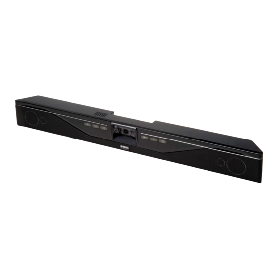
Microphones Call Status Status + NFC Pairing The main CS-700 Unit contains all the major components of the CS-700 System, including 4 Speaker Elements, 4 beam forming microphones, the optimized 120° FoV HD camera, and front-panel control buttons for: volume up/down, MIC mute, Camera mute, Bluetooth pairing, NFC Bluetooth pairing. - Page 10 Slow Flash Red Bluetooth Indicator and NFC Pairing The Bluetooth indicator shows whenever the CS-700 is in active pairing mode (flashing blue) or has actively connected with a local Bluetooth device (steady blue). The NFC paring indicator enables Bluetooth devices capable of NFC pairing to do so with the CS-700.
- Page 11 System Call Status Indicator The System Call Status Indicator located immediately below the Yamaha logo shows whenever the CS-700 is actively engaged in a call or not. It also shows whenever a hardware failure has been detected by turning RED. The following...
-
Page 12: Installing The System
If installed below the display ensure that the distance is big enough to fit the CS-700 unit. You can adjust the depth of the installation by using the appropriate number of spacers (0-2) on each side. -
Page 13: Placing The Cs-700 Unit On The Bracket
Placing the CS-700 unit on the bracket Position the CS-700 in such a way that the two hooks in the front of the bracket fit into the cavities on the lower part of the CS-700. Ensure that the CS-700 is safely held by the hooks. -
Page 14: Installing Unit In Bracket
Installing unit in Bracket Once all cables are correctly connected and secured, tilt the CS-700 back on the bracket and push it pack into the bracket. Secure unit Secure the CS-700 unit in the bracket with the provided machine screws. -
Page 15: Setting Up The System
Setting up the system All connectors can be found on the back of the main CS-700 unit. AUX-In Extension Microphone Power Ethernet Port USB Port Multipurpose USB Port Connecting the Power Connect one end of the power supply cable into the Power Connector on the CS-700 back panel. -
Page 16: Connecting To A Computer - Usb 3.0
USB 3.0 compliant and certified for video applications. Find a list of approved USB 3.0 extension cables in the appendix. Be sure the PC USB Port supports USB 3.0. The camera of the CS-700 will send an uncompressed 1080p HD image over HD 3.0. -
Page 17: Connecting To An Ip Network For System Management And Sip Telephony
Discovering IP Address The IP Address is assigned to the CS-700 either by the DHCP protocol, or statically via the CS-700 configuration. When using DHCP, the IP Address assigned to the CS-700 unit can be discovered three ways. -
Page 18: Connecting Extension Microphone
To help secure the cables connected to the CS-700 main unit, indents are provided on the back casing to support the included “hook-and-loop” cable ties. Cables can be secured and tied-off on the back of the CS-700 to ensure robust cable connections. - Page 19 Procedure for camera angle Camera Angle Adjustment adjustment 1. Connect a PC through the CS-700 USB cable, and enable UC software, a local PC camera application, or the Service Application. 2. Engage the UC Software / PC application / Service Application to display the CS-700 camera onto the local PC screen.
-
Page 20: User Interface
Volume Up/Down buttons affect the sound from the CS-700, with corresponding increasingly or decreasingly loud “beeps” occurring with each press. The CS-700 will default the sound level to a pre-set value following each new USB connection session. Mute status is reflected on the color of the Mute Buttons. - Page 21 When accessing the CS-700 Web-UI webserver, the login page will be displayed. A password is required to log in to the device. Unless the password was previously changed, the factory default password is 7386. Generally, after a time-out period the user will be automatically logged-out of the web interface.
- Page 22 The home screen allows initiating an immediate restart of the device, by clicking on the Restart Device box. In all screens of the web UI, a logout icon is displayed in the upper right corner allowing the user to log off from the unit. The top menu line allows accessing the different pages of the web UI.
- Page 23 Once a valid password has been entered, it needs to be entered a second time to protect against typos and unwanted changes. System Name allows the administrator to provide a descriptive name to the CS- 700. Factory default this name is CS-700 and the MAC address.
- Page 24 Security Settings The “Enable recent calls” selection enables / disables keeping a list of the last phone calls made from or to the CS-700. When disabled no information on the calls will be kept on the system. When “Require HTTPS” is enabled, the web interface will switch from http to https.
- Page 25 DnD functionality can be enabled or disabled for the user. Front Panel Settings All of the front-panel CS-700 control buttons can be individually enabled or disabled through these check boxes. De-selecting the respective setting will disable the corresponding front panel button and light.
- Page 26 This feature is set by factory default with a 20 minute power savings time. The CS-700 will wake up when activity is detected, either on the Aux in, the USB connection, or a button is pressed. Please allow about 10 seconds for the system to wake up.
- Page 27 SNMP Settings The CS-700 will report SNMP MIB events (Traps) and provide status updates to SNMP polls when this feature is enabled with the Enable SNMP box. Provide the SNMP server IP address to complete the process. See the Appendix for details on the SNMP MIB and traps supported.
- Page 28 When using the static server addresses, TFTP addresses or HTTP addresses might be provided. When using the deployment server, the CS-700 will look for a file named <<MAC-address of unit>>.xml in the provided location(s). See the remote configuration section for sample configuration and a list of the available configuration parameters.
- Page 29 The Equalizer setting allows selecting one of a list of pre-defined speaker equalizations. The available choices are Voice Enhance, Bass Boost, and Treble Boost. The High Pass filter affects the microphones and can be used to filter out low frequency noises in the room. The high pass filter can be disabled (None), or set to the provided frequencies of 110Hz, 140Hz, 175Hz, or 225Hz.
- Page 30 Media Settings Media Settings allows the administrator to select the VoIP codecs that are enabled / disabled in the unit by dragging and dropping them into the according areas. Within the enabled area, the order from top to bottom gives the ranking in which the codecs will be offered.
- Page 31 The “Enable Bluetooth” box allows system-wide control of all Bluetooth capability. De-selecting this box will shut-down Bluetooth communications to the CS-700 and disable the Bluetooth and NFC front-panel indicator buttons. System defaults to Bluetooth-enabled. The “Enable NFC” box allows control over the NFC pairing feature. De-selecting this box will disable the NFC pairing feature associated with the NFC front- panel indicator button.
- Page 32 Calls The calls section allows defining behavior and options available to the user around call behavior. Enable Message Waiting indicator allows the dialer to show information on possible voice messages that are stored on the server for this number. Set DnD puts the phone into this mode by default. Enable auto-answer automatically answers any incoming call.
- Page 33 Maximum call duration allows setting a maximum number for a phone call in minutes. The default of “0” means no maximum. If a dial plan is required for the phone please enter the dial plan string here. See the Appendix for a definition of the dial plan string. Forwarding Settings The Forwarding settings allow specifying under which conditions calls should be forwarded, and to which number.
- Page 34 Service Application described later in this document, or using UC applications that offer camera control. Note that in the CS-700 Pan and Tilt settings are only effective when Zoom has been set to a value greater than one.
- Page 35 Return to default image settings returns the settings to the factory default. Finally, the Power Line Frequency for Anti-Flicker setting allows selecting the frequency of the power line. In environments using florescent lighting the image of the CS-700 might be flickering unless the images sent are adjusted to the power frequency.
- Page 36 Network The Network section allows specifying the IP configuration for the CS-700. Factory default, the device is set to DHCP enabled and no further IP settings are required. However, if a static IP address is to be assigned, “Enable DHCP”...
- Page 37 Authentication Settings Authentication Settings provides the option to enable 802.1x authentication on the CS-700. To enable 802.1x authentication, check the Enable 802.1x authentication setting. Supported authentication type is MD5. A username and password are needed to complete the authentication process.
- Page 38 The Regional call progress tones allow adapting the tones heard while setting up calls to the local typical tones. Finally, the Time zone setting allows selection of the time zone the CS-700 is being used in, managing date and time reported in network management and...
- Page 39 Time Settings In the Time Settings section the date format used can be selected. Date can be set as MM/DD/YYYY, DD/MM/YYYY, or YYYY/MM/DD. The time display can be changed between 24 hour format and 12 hour format. Factory default is MM/DD/YYYY and 12 hour format.
- Page 40 Region: Daylight Savings Settings Daylight Savings settings allow to enable or disable Daylight Savings time. If enabled, rules for the start date and time as well as the end date and time need to be provided. Factory default US daylight savings time is enabled and configured.
- Page 41 In this menu the SIP configuration settings are located configuring the CS-700 with the call manager. Registrar and Back-up registrar (if configured) are the IP addresses or domain names of the Call Manager. If configured, a Proxy address can be provided, and an indicator whether the proxy should also be used for...
- Page 42 The next section contains the user name, User ID and password for the logon to the Call Manager. Please note that Call Managers often use different names for these parameters and a correct mapping is required for the logon to the call manager to be successful.
- Page 43 The Configuration Settings section offers several advanced SIP settings. These parameters should be aligned with the call manager configuration.
- Page 44 This setting allows headers of messages in abbreviated format. Ensure that your Call Manager supports minimized SIP message. The CS-700 supports several means to transport DTMF information entered during a call to the far end. This setting should be consistent with the method supported by the call manager.
- Page 45 The remaining parameters on this page allow specifying the ports used for communication from the device, enable secure RTP, and ICE, TURN, and STUN settings. These parameters should reflect the call manager and network environment in which the CS-700 is used.
- Page 47 Update Update allows upgrading the device firmware of the CS-700 using an image bundle on your local PC. Only valid firmware files can be used for an upgrade. Latest firmware can be found on https://uc.yamaha.com/products/video- sound-bar/huddle-room-system.
- Page 48 Configuration The configuration page allows Exporting and re-Importing the current configuration of the CS-700. This is specifically of interest if several CS-700 devices are to share identical configurations. The first CS-700 can be fully configured and exported as a “Golden Reference” configuration for the rest of the CS-700 estate.
- Page 49 Restore to Factory Defaults restores all settings back to the original settings. Logs The Logs section allows downloading logging information from the CS-700 for analysis. By Factory Default, verbose logging is not enabled and not required. Access to logging information is typically only required when environmental issues with connected devices are experienced.
-
Page 50: Service Application
Service Application The CS-700 device can also be configured and managed through a PC connected via USB using a software client called the “Service Application”. The Service Application enables the locally attached Computer to gain access to the CS-700 configuration and operating parameters over the USB cable. Under... - Page 51 Next the installer requires the path where the application shall be installed. Please accept the path, or provide the location where the application shall be installed.
- Page 52 On the next screen select if a desktop shortcut is required:...
- Page 54 Finally, please confirm the selections and start the installation process.
- Page 56 The service application requires an additional device driver for the USB interface which requires confirmation: Finally, a window with help information is provided.
- Page 57 And lastly, the installation process provides a success message after a successful installation.
-
Page 58: Using The Service Application
USB connection is displayed. If a CS-700 device is connected and detected no an USB connection, the service application will request the password to access the system. The password is... - Page 59 Once the application logged into the CS-700 device, the home tab will show status information of the unit. As in the web UI, changes to parameters require selecting “Submit” for these changes to be sent to the CS-700. If not pressing “Select” and leaving the page, changes will be lost.
- Page 60 System Name allows the operator to change the reported name of the CS-700 unit, instead of using the MAC address. All of the front-panel CS-700 control buttons can be individually enabled or disabled through these check boxes.
- Page 61 This feature is set by factory default with a 20 minute power savings time. The CS-700 will wake up when activity is detected, either on the Aux in, the USB connection, or a button is pressed. Please allow about 10 seconds for the system to wake up.
- Page 62 Operator to select a pre-defined gain level from -12dB to +40dB. Note: The signal received on the Aux-in port is not mixed into any output stream. It is only played back in the room using the speakers supporting a sound bar application of the CS-700.
- Page 63 The system default is Bluetooth-enabled. The Device Name allows modification of the Bluetooth advertised device name. The default value is Yamaha CS-700:<last 4 characters of MAC of this device>. The Pairing PIN defines the 4-digit Bluetooth Basic Rate PIN for pairing, with default set to “0000”.
- Page 64 Once satisfied with the settings, they can be saved as PTZ Home. The PTZ Home settings are automatically applied every time a new USB connection is being made to the CS-700. Clicking on Go to PTZ Home will restore the camera to the stored PTZ home values.
- Page 66 Network The Network section allows specifying the IP configuration for the CS-700. Factory default, the device is set to DHCP enabled and no further IP settings are required. However, if a static IP address is to be assigned, “Enable DHCP”...
- Page 67 Update The update section allows updating the firmware of the Yamaha CS-700. After clicking on “Select firmware” browse to the location where the firmware file is being stored and select it. Uploading the firmware file using USB will take several minutes, a progress...
- Page 68 Configuration The configuration tab allows Exporting and Importing configuration information of the CS-700. This is specifically of interest if several CS-700 devices are to share identical configurations. The first CS-700 can be fully configured and exported as a “Golden Reference” configuration for the rest of the CS-700 estate.
- Page 69 Logs The Logs section allows downloading logging information from the CS-700 for analysis. Access to logging information is typically only required when environmental issues with connected USB devices are experienced, and usually are shared with Yamaha Customer Support.
-
Page 70: Dialer Application
To allow managing SIP and USB calls in the SIP versions of the product, Yamaha provides an Android application. This Android app transforms a IP Wired or wireless tablet into a wireless “dialer” for the CS-700. Supported Tablets The minimum Operating System version required is Android 5.1. -
Page 71: Dialer Interface
The microphone symbol on the bottom indicates the microphone mute status of the CS-700. Touching this symbol will toggle between unmuted (green) and muted (red). The other symbols on the bottom indicate the current call state for the SIP lines, the USB connection, and Bluetooth. Grayed out means that the... -
Page 72: Main Menu
It shows information on the dialer software version, the connection that is used between the dialer and the CS-700, and the name of the CS-700 system if it is connected wirelessly. Below that the menu offers options to go back... -
Page 73: Contacts
Contacts When selecting “Contacts”, an alphabetic list of the contacts stored on the CS-700 will be displayed. Selecting any of the names will open the contact. Pressing the symbol with the “+” in the top right will open a new contact. -
Page 74: Call History
Call History The call history page lists a history of the last 100 incoming, outgoing calls, failed, and missed calls. The call history can be searched by typing in a search string in the magnifying glass area. The search is done against the telephone number or the stored name of a contact, and shows any matches against the search string. -
Page 75: Connection
Connection The menu entries provide information on the connection to the CS-700. Settings The Settings menu allows changing the volume for the ringer as well as the speaker output during a call. It also allows changing the brightness of the dialer LCD-screen. -
Page 76: Dialing And Call Control
As mentioned earlier, the bottom line of the dialer indicates activity of the different supported communication channels. Generally, if a USB cable is connected to the CS-700 and activity is being detected, the USB line is active. If no activity is detected, the symbol will be greyed out. Similarly, when a Bluetooth call is detected, the Bluetooth symbol will show activity. - Page 77 For audio control, the volume up and volume down button on the dialer screen are synchronized with the CS-700 audio behavior. The microphone mute button on the bottom is also synchronized with the mute behavior of the CS-700.
- Page 78 To reject the incoming call press the red handset symbol. Switching active call When several calls are handled by the CS-700 concurrently, the user can switch between the calls by simply selecting and touching the entry for the call on the dialer display. Calls...
- Page 79 Conference call All call instances handled by the CS-700 can be placed into conference with each other. If calls are already established (and on hold) they can join the active call by pressing the “join” button. Similarly, a call can be taken out of a conference by pressing “split”.
- Page 80 USB and Bluetooth calls USB and Bluetooth calls will provide a similar user experience to VoIP calls on the dialer. Users will have similar controls for Bluetooth and USB calls as are provided for the VoIP calls.
-
Page 81: Basic Operations
When changing any of these settings using the UC application, the CS-700 will return to its factory default values and “PTZ Home” settings once the USB connection is interrupted. A new user entering the room to use the CS-700 will find the system back with the preset values. -
Page 82: Aux-In Audio Support
Aux-IN Audio Support To utilize the CS-700 as a room speaker system such as for the display in TV mode, connect your source of audio via a standard 3.5mm stereo jack connector on the back of the unit. Gain is automatically adjusted by default and the Volume Up/Down controls will manage the sound level. -
Page 83: Configuring The Cs-700
CS-700 and to enter in specific information. There are three methods to configure the CS-700: from the Web UI over IP network, using the Service Application on a local USB-attached PC, or using a provisioning server and provisioning file with DHCP Option 66 or 150. -
Page 84: Configuring Using A Provisioning Server, Option 150
<username> and <password> are the username and password required to access a TFTP server. Once the CS-700 receives the address information of that server, it tries to access configuration files on that server to auto-configure the device during start-up. The configuration file for the specific CS-700 device needs to be named <MAC-address of device>.xml. -
Page 85: Provisioning File
F0DEF1A064E6.xml F0:DE:F1:A0:64:E6. Please note that all letters need to be upper case in the file name. <provisioning include="enterprise.xml, department.xml"> <config sys.password ="1234" /> </provisioning> Include files Filename: enterprise.xml <provisioning> <firmware version="1.1.0.180">CS-700-1-1-0-180.bundle</firmware> <config audio.eq ="0" audio.def-speaker-volume ="5" audio.high-pass-filter ="3" /> </provisioning>... -
Page 86: Provisioning File Parameters (All Models)
The following table lists the attributes that can be provided as part of a provisioning file for CS-700, applicable to all models. If a specific attribute is not provided and the value is not set in the device, the default value as... - Page 87 Property Type Values Default Value Description sys.systemname TEXT System name string. Product name Specifies the system name. Default value is the product and MAC name concatenated with the Address MAC address sys.md5-password TEXT Password string. 7386 (as MD5 Administrator password for the device, stored as MD5 sum. sum) sys.enable-btn- BOOLEAN...
- Page 88 Property Type Values Default Value Description sys.region INDEXED_ 1 : Argentina Region in which device is operating, setting by index. OPTION 2 : Australia 3 : Belgium 4 : Brazil 5 : Canada 6 : Chile 7 : China 8 : Costa Rica 9 : France 10 : Germany 11 : Hong Kong...
- Page 89 Property Type Values Default Value Description sys.time-zone INDEXED_ 0 : -11:00 American Samoa Time zone setting by index. OPTION 1 : -10:00 Hawaii 2 : -9:00 Alaska 3 : -8:00 Pacific Time 4 : -7:00 Mountain Time 5 : -6:00 Central Time 6 : -5:00 Eastern Time 7 : -4:30 Caracas 8 : -4:00 Atlantic Time...
- Page 90 Property Type Values Default Value Description sys.power-saving- BOOLEAN 0 : Power save mode is off Configure the power saving mode setting. mode 1 : Power save mode is on sys.power-saving- NUMBER timeout : Power save timeout in Configure power saving time in minutes. time minutes sys.provisioning-...
- Page 91 Property Type Values Default Value Description audio.high-pass- INDEXED_ 0 : None High-Pass filter setting. High-Pass filters are provided to adjust to filter OPTION 1 : 110 Hz room and application requirements. Use the High-Pass filter in 2 : 140 Hz rooms that have a high background noise in the low frequencies 3 : 175 Hz (air conditioning, lighting fixtures, etc.).
- Page 92 0 : disable Enable or disable Bluetooth basic-rate. 1 : enable bt.bt-name TEXT Name of device. "Yamaha CS- The Bluetooth basic-rate device name advertised over the air. Default value is the product 700 " + BT MAC name concatenated with the address system's BT MAC address bt.bt-pin...
- Page 93 Property Type Values Default Value Description net.dot1x-enabled BOOLEAN 0 : Disable 802.1x authentication Enables 802.1x authentication to access the network. When 1 : Enable 802.1x authentication enabled, the required MD5 credentials – identity and password - also need to be specified. net.dot1x-identity TEXT username : String.
- Page 94 Property Type Values Default Value Description voip.reg-timeout NUMBER 1..604800 : Registration timeout Registration Timeout is the optional timeout for SIP account in seconds registration, in seconds. The maximum is 604800, which is 7 days. voip.rereg-delay NUMBER 1..604800 : Auto re-registration Configure auto re-registration retry interval in seconds.
- Page 95 Property Type Values Default Value Description voip.dtmf-method TEXT 0 : RTP -- RFC2833 DTMF signaling method. 1 : SIP INFO 2 : In-band voip.dtmf-rtp- TEXT 96..127 Specify the dynamic RTP payload type for DTMF transport using payload-type RTP. voip.media- BOOLEAN 0 : M line only -- RFC3264 The Media on Hold method setting allows switching the Media on onhold-method...
- Page 96 Property Type Values Default Value Description voip.ip-addr TEXT ip-address : IP address Configure optional address to advertise as the address of this transport. Can specify any address or hostname for this field. For example, it can point to the public address of a NAT router where port mappings have been configured for SIP.
- Page 97 Nomination Method. To validate candidate pairs (IP addresses and method ports for the local and remote nodes), CS-700 sends STUN binding requests as part of the media connectivity tests. When a candidate is nominated for use, a STUN binding request is sent with a flag indicating that the candidate pair is nominated.
- Page 98 Property Type Values Default Value Description candidate pairs when determining the best route. A value of 0 indicates that there is no maximum. voip.ice-no-rtcp BOOLEAN 0 : Do not disable RTCP Option to not disable the RTCP component in ICE. 1 : Keep RTCP disabled voip.use-turn BOOLEAN...
- Page 99 Property Type Values Default Value Description voip.codec3 INDEXED_ 0 : None Third highest prioritized codec. At least one codec different from OPTION 1 : G.722 “None” has to be selected in voip.codec1-voip.codec5. 2 : G.711 u-law (PCMU) 3 : G.711 A-law (PCMA) ) 4 : G.726 5 : G.729 voip.codec4...
- Page 100 Property Type Values Default Value Description voip.duration NUMBER 0 : No maximum Specifies the maximum VoIP call duration in minutes. When the 1..10080 : Maximum VoIP call call duration reaches the maximum duration, the call will be duration in minutes automatically terminated.
-
Page 101: Using The Application Programming Interface (Api)
Using the Application Programming Interface (API) The Yamaha CS-700 provides an interface to integrate into third party applications to control and manage the unit directly without the use of Yamaha’s management interfaces. The API allows accessing the CS-700 unit either over an USB connection or the network. Use cases are for example integrations with room control systems. - Page 102 event_callback Pointer to callback function to handle events. type Type of event as listed in table below. Return Values: Value Description General error Success No device connected Failed authentication Event Types: Type Description 0xFF Device disconnected devDetach Description: Disconnect session. Syntax: EXPORT void __cdecl devDetach(void);...
- Page 103 coreCliCmd Description: Send a CLI-format command to the device. Commands are listed in the section “USB/Telnet CLI Commands”. Syntax: EXPORT int __cdecl coreCliCmd(char *cmd, char* rsp, int len); Parameters: Parameter Description CLI command string (see API Command Reference) Pointer to response string Bytes available in response string Return Values: Value...
-
Page 104: Telnet / Ip Interface
Telnet / IP interface To use an IP connection for the control, with the CS-700 being the server, the “Enable telnet access” check box on the Admin Settings page of the web UI has to be checked. Start the telnet connection by connecting to the IP address of the CS-700 unit, providing the standard Telnet port number 23. - Page 105 <0..10> A range of values is separated by an ellipsis. <"paired"> [<"mac"> <"name">] Square brackets designate optional parameters. [<"mac"> <"name">]+ A list of repeating values is designated by a plus sign. For properties, the description lists the actions that can be performed on the property, including: get –...
- Page 106 Command Definition: Action Definition get speaker-volume val speaker-volume <1..18> response set speaker-volume <1..18> notify audio.speaker-volume <1..18> notify Parameters: Parameter Description Volume setting 1 .. 18 Format Examples: get speaker-volume val speaker-volume 13 set speaker-volume 13 notify audio.speaker-volume 13 Supported Products: CS700-AV, CS700-SP ringer-volume Description: Configure VoIP ringer volume.
- Page 107 speaker-mute Description: Query speaker mute status. Property Actions: get, notify Command Definition: Action Definition get speaker-mute val speaker-mute <0|1> response notify audio.speaker-mute <0|1> notify Parameters: Parameter Description Speaker is not muted Speaker is muted CLI Format Examples: get speaker-mute val speaker-mute 1 notify audio.speaker-mute 1 Supported Products: CS700-AV, CS700-SP, CS700-DL, CS700-DS mute...
- Page 108 Description: PTZ settings for the default home position. When the CS-700 detects that an USB connection has been established to a computer, either at startup or after a previous USB disconnection, it will revert to the PTZ home settings. Calling set on this property will move the camera to the newly defined PTZ position.
- Page 109 Property Actions: set, get, notify Default Values: 3 125 110 100 85 90 220 Command Definition: Action Definition get camera-image-defaults val camera-image-defaults <"backlight"> <"brightness"> response <"contrast"> <"saturation"> <"sharpness"> <"hue"> <"gamma"> set camera-image-defaults <"backlight"> <"brightness"> <"contrast"> <"saturation"> <"sharpness"> <"hue"> <"gamma"> notify camera.camera-image-defaults <"backlight"> <"brightness"> notify <"contrast">...
- Page 110 notify camera.camera-backlight <0..5> notify Parameters: Parameter Description Camera backlight level. 1..5 CLI Format Examples: get camera-backlight val camera-backlight 3 set camera-backlight 3 notify camera.camera-backlight 3 Supported Products: CS700-AV, CS700-SP camera-mute Description: Camera video "mute” or stop state. Property Actions: set, get, notify Command Definition: Action Definition...
- Page 111 Property Actions: set, get, notify Default Value: Command Definition: Action Definition get camera-pan val camera-pan <-30..30> response set camera-pan <-30..30> notify camera.camera-pan <-30..30> notify Parameters: Parameter Description Pan setting -30 .. 30 Format Examples: get camera-pan val camera-pan 0 set camera-pan 0 notify camera.camera-pan 0 Supported Products: CS700-AV, CS700-SP, CS700-DL, CS700-DS cam-pan-left...
- Page 112 Action Definition cam-pan-right Execute notify camera.pan <-30..30> Notify Parameters: None CLI Format Examples: cam-pan-right notify camera.pan 8 Supported Products: CS700-AV, CS700-SP, CS700-DL, CS700-DS camera-tilt Description: Camera's digital tilt setting. Camera can only be tilted when zoomed in. Property Actions: set, get, notify Default Value: Command Definition: Action...
- Page 113 notify camera.tilt <-18..18> Notify Parameters: None CLI Format Examples: cam-tilt-up notify camera.tilt 8 Supported Products: CS700-AV, CS700-SP cam-tilt-down Description: Decrease the current camera tilt by one. Command Definition: Action Definition cam-tilt-down Execute notify camera.tilt <-18..18> Notify Parameters: None CLI Format Examples: cam-tilt-down notify camera.tilt 5 Supported Products: CS700-AV, CS700-SP, CS700-DL, CS700-DS...
- Page 114 get camera-zoom val camera-zoom 1 set camera-zoom 1 notify camera.camera-zoom 1 Supported Products: CS700-AV, CS700-SP, CS700-DL, CS700-DS cam-zoom-in Description: Zoom in by one level. Command Definition: Action Definition cam-zoom-in Execute notify camera.zoom <1..22> Notify Parameters: None CLI Format Examples: cam-zoom-in notify camera.zoom 2 Supported Products: CS700-AV, CS700-SP cam-zoom-out...
- Page 115 Command Definition: Action Definition cam-apply-defaults execute Parameters: None Format Examples: cam-apply-defaults Supported Products: CS700-AV, CS700-SP cam-image-apply-defaults Description: Apply the camera's default Backlight, Brightness, Contrast, Saturation, Sharpness, Hue, and Gamma settings. These settings are also automatically applied when the device detects that the upstream USB connection has been established, either at startup or after a USB disconnection.
- Page 116 Supported Products: CS700-AV, CS700-SP status-all Description: Query all call status. See "call-status" property for description of status types. Status information on VoIP lines is only provided in the –SP and –DS version of the CS-700 product. Property Actions: Command Definition:...
- Page 117 get status-all val status-all line1:<”status1”> line2:<”status2”> response line3:<”status3”> bt:<”statusbt”> usb:<”statususb”> Parameters: Parameter Description VoIP line 1 call status status1 VoIP line 2 call status status2 VoIP line 3 call status status3 Bluetooth call status statusbt USB call status statususb Format Examples: get status-all val status-all line1:disabled line2:disabled line3:disabled bt:idle usb:idle Supported Products: CS700-AV, CS700-SP, CS700-DL, CS700-DS...
- Page 118 Property Actions: Command Definition: Action Definition get start-time <1..3> val start-time <1..3> <"time"> response Parameters: Parameter Description VoIP line 1 VoIP line 2 VoIP line 3 (used for transfer) time HH:MM:SS in 24-hour time format CLI Format Examples: get start-time 1 val start-time 1 13:22:41 Supported Products: CS700-SP dial...
- Page 119 Action Definition answer <1..2|usb|bt> execute Parameters: Parameter Description VoIP line 1 VoIP line 2 VoIP line 3 (used for transfer) USB connection Bluetooth connection Format Examples: answer Supported Products: CS700-AV, CS700-SP hangup Description: Hang up the given call. Command Definition: Action Definition execute...
- Page 120 VoIP line 1 VoIP line 2 VoIP line 3 (used for transfer) USB call/audio BT call All active calls Format Examples: hold Supported Products: CS700-AV, CS700-SP resume Description: Resume the given call. Command Definition: Action Definition resume <1..3|usb|bt> execute Parameters: Parameter Description VoIP line 1...
- Page 121 Line ID of call that is currently active; this call will be placed on hold active-line-id <1..3|usb|bt> Format Examples: swap Supported Products: CS700-AV, CS700-SP join Description: Join allows the individual lines to be mixed (joined) or not mixed (separated). Used for conferencing existing calls.
- Page 122 Action Definition transfer <"source-line-id"> <"target-line-id"> execute Parameters: Parameter Description Line ID of call being transferred source-line-id <1..2> Line ID of call to which the source will be transferred target-line-id <3> Format Examples: hold 1 dial 3 5555555555 transfer 1 3 Supported Products: CS700-AV, CS700-SP vm-count Description:...
- Page 123 Command Definition: Action Definition get do-not-disturb val do-not-disturb <0|1> response set do-not-disturb <0|1> notify voip.do-not-disturb <0|1> notify Parameters: Parameter Description Disable DND Enable DND Format Examples: get do-not-disturb val do-not-disturb 0 set do-not-disturb 0 notify voip.do-not-disturb 0 Supported Products: CS700-SP dtmf Description: Send DTMF digit on given VoIP line during an active call.
- Page 124 Description: Query SIP registration status. Property Actions: get, notify Command Definition: Action Definition get registration val registration <"status"> response notify voip.registration <"status"> notify Parameters: Parameter Description unregistered Unregistered to SIP server registering Registration is in process registered Registered to SIP server registration- Registration attempt failed failed...
-
Page 125: Upgrading The Device Firmware
. The https://uc.yamaha.com/products/video-sound-bar/huddle-room-system/ software is packaged as a bundle file which is applied to the CS-700 directly through the Web-UI, the Service Application, or the provisioning file. The file will have a naming convention with suffix “.bundle” at the end. -
Page 126: Appendix
USB 3.0 Extension Cables The following USB extenders have been tested for use with the CS-700 and shown good results. Please note that we cannot give guarantees that these products will work in all environments. The distance supported by each USB extender varies and is defined by the manufacturer’s specifications:... -
Page 127: Snmp Support Details
SNMP Support Details The CS-700 includes an SNMP agent that can be configured to provide SNMP support. The table below describes the SNMP configuration settings that the CS-700 administrator must configure to enable SNMP. snmp-enable Enable or disable SNMP support. Disabled (0) means that SNMP is not supported. -
Page 128: Snmp Mib For The Cs-700
"postal: Yamaha Unified Communications 144 North Rd Sudbury, MA 01776 email: uc-customersupport@music.yamaha.com" DESCRIPTION "Defines monitoring structures for the Yamaha SNMP agent for CS-700." REVISION "201710010000Z" DESCRIPTION "Initial revision" ::= { enterprises 1182 } cs700 OBJECT IDENTIFIER ::= { yamahaAgentMIB 7386 }... - Page 129 ::= {cs700 17} voipCallStatus OBJECT-TYPE SYNTAX DisplayString MAX-ACCESS read-only STATUS current DESCRIPTION "Current VoIP call lines 1-3 call state of type String." ::= {cs700 18} -- CS-700 traps usbConnTrap OBJECT-TYPE SYNTAX DisplayString MAX-ACCESS accessible-for-notify STATUS current DESCRIPTION "USB connection trap data"...
- Page 130 STATUS current DESCRIPTION "Generated when USB connection state changes" ::= { cs700Traps 1 }...
-
Page 131: Dial Plan Definition
Dial Plan definition The dial plan serves several purposes. It allows manipulating a number string that is entered on the dialer and instead sends a transformed string to the Call Manager. Or it allows checking for specific strings to be blocked for dialing. Any string dialed is checked against the dial plan and returns "no match", "match"... -
Page 132: Examples
Examples • <9:>xxxxxxx—Remove 9 at the beginning of the dialed number — For example, if the number 914539400 is dialled, the first 9 is removed when the call is placed. • <:604>xxxxxxx—Prepend 604 to all seven digit numbers — For example, if a customer dials 4539400, 604 is added to the front of the number, so a call to 6044539400 is placed. -
Page 133: Optimize Windows For Cs-700 Audio
Optimize Windows for CS-700 Audio To configure the CS-700 device as the default device and to improve audio follow this one-time setup procedure: Right click on the speaker icon in the lower right hand corner of the Windows taskbar. Select Sounds from the menu. -
Page 134: Troubleshooting
Cannot Access Web UI Check that the IP Address being used is correct. The IP Address of the CS-700 device is provided by simultaneously pressing and holding the “Volume-UP” and “Bluetooth” buttons on the front panel for five seconds. The CS-700 unit will announce the currently assigned IP Address. -
Page 135: Lost Password
Several factors along the system chain include the following: • USB Connection from CS-700 to the local PC device. This link must be at full 3.0 specification to ensure sufficient bandwidth necessary to support HD-video transfers. -
Page 136: Misaligned Camera Image (Far-End Video)
If the camera is projecting a poorly framed (misaligned) image to the far-end. Or the conference room is configured such that the CS-700 is not symmetrically aligned with the Table and/or the display, causing the camera field of view to be misaligned. -
Page 137: Technical Specifications
Technical Specifications Power adapter Model Number ADP-38DR A Bluetooth Specifications Bluetooth specification version 2.1 + EDR Supported profiles HFP (1.6), A2DP Supported Codecs SBC, mSBC, CVSD Wireless output Class 2 Maximum communication 10 m distance Radio frequency (Operational 2,402 MHz to 2,480 MHz frequency) Maximum output power (EIRP) 4.0 dBm (2.5 mW) -
Page 138: Date Code
-22 to 131 °F (-30 to 55 °C) Operating / Storage Relative 20%-85% (non-condensing) Humidity Maximum operating altitude 2,000m Date code The date code on the CS-700 label indicates when the product was manufactured. The first digit indicates the year. First Calendar digit year 2017... - Page 139 2020 2021 The second and third digits indicate the calendar week in that year – from 01 at the beginning of the year to 52 (or 53). For clarification, the year and months are also provided in the format YYYY/MM.
-
Page 140: Limited Warranty And Limitation Of Liability
Yamaha Unified Communications’ sole obligation under this express warranty shall be, at Yamaha Unified Communications’ option and expense, to repair the defective product or part, deliver to Customer an equivalent product or part to... -
Page 141: Exclusions And Remedies
Yamaha Unified Communications Product Repair Policy. The sole exceptions to the terms of this warranty are those listed as part of the Yamaha Unified Communications DOA Replacement Policy. -
Page 142: Limitation Of Liability
PERSON TO ASSUME FOR IT ANY OTHER LIABILITY IN CONNECTION WITH THE SALE, INSTALLATION, MAINTENANCE OR USE OF ITS PRODUCTS. Limitation of Liability TO THE FULL EXTENT ALLOWED BY LAW, YAMAHA UNIFIED COMMUNICATIONS EXCLUDES FOR ITSELF AND ITS SUPPLIERS ANY LIABILITY, WHETHER BASED IN CONTRACT OR TORT (INCLUDING... - Page 143 Open Source Software The following table lists the open source software in the CS-700 products and the respective licenses under which these software packages are used. The specific Open Source software packages used in the CS-700product are: Name Version License Type psp_linux 12.0...
- Page 144 Cisco https://github.com/cisco/libsrtp Metaparadigm Pte Ltd https://github.com/json-c/json-c/blob/master/COPYING Source code for these open source software packages can be obtained by contacting Yamaha Unified Communications at uc-support@music.yamaha.com.
- Page 145 © Yamaha Corporation. All Rights Reserved. Published 4/2019 D0 M N - C S 7 0 0 - 2 0 1 9 0 4 - E N / 295 02 74-00 Manufacturer: Yamaha Unified Communication, Inc. Address: 144 North Road, Suite 3250...