
Related Manuals for GE Masoneilan VariPak 28001


Summary of Contents for GE Masoneilan VariPak 28001
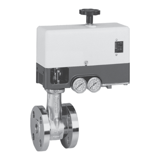
- Page 1 GE Oil & Gas 28000 Series Masoneilan* VariPak* Adjustable-C v Control Valves Instruction Manual...
- Page 2 OR SHOULD PARTICULAR PROBLEMS ARISE WHICH ARE NOT COVERED SUFFICIENTLY FOR THE CUSTOMER/OPERATOR'S PURPOSES THE MATTER SHOULD BE REFERRED TO GE. THE RIGHTS, OBLIGATIONS AND LIABILITIES OF GE AND THE CUSTOMER/OPERATOR ARE STRICTLY LIMITED TO THOSE EXPRESSLY PROVIDED IN THE CONTRACT RELATING TO THE SUPPLY OF THE EQUIPMENT.
-
Page 3: Table Of Contents
Contents 1. General ..................... . 4 1.1 Spare Parts . -
Page 4: General
GE representative or the Training Department at the Condé-sur-Noireau plant, in France. 1.2 AFTER SALES DEPARTMENT GE has a highly skilled After Sales Department to assist customers with start-up, maintenance, and repair of valves and instruments. Contact your nearest GE Sales Office or Representative, or the After Sales Department at the Condé-sur-Noireau plant, in France. -
Page 5: Operation
2. Operation 2.2 FLOW COEFFICIENT OF VARIPAK 28001 The Masoneilan VariPak microflow control valve SINGLE-LEVER AND 28002 ADJUSTABLE-C v features a very wide range of rated flow coefficients VALVES (C v ), from 0.004 to 3.8. Two types of actuators are available: 2.2.1 Plug/seat ring combinations (trim) - The VariPak 28001 with a single lever, designed for Eight plugs and five seat rings are used to... - Page 6 0.25 to 1.10 0.10 to 0.04 0.050 to 0.020 3-15 Green 1.4 (20) 1.4 (20) 1.4 (20) 0.025 to 0.010 (25) 1035 0.010 to 0.004 0.004 to 0.0016 Figure 3 - Actuator spring ranges and supply pressures GE Oil & Gas...
-
Page 7: Actuator
Follow the procedure described in the "Disassembly/ - Loosen adjustment knob (24) and slide it along the Reassembly" section of the "Maintenance" chapter on lever to the required value. Tighten the adjustment pages 14 to 18. knob again firmly. Note: - Also change the serial plate (135) or correct the information on the existing plate. -
Page 8: Reversing The Valve Action
I. Refit levers No. 1 and 2 in sequence, making sure that Unhook spring (114) from spring clamp (115). pins (105) and (108) are fitted into the correct holes in the levers and bracket for the new action of the actuator (see figure 6). GE Oil & Gas... - Page 9 Note: Ensure that the clevis is correctly positioned before N. Put the valve back into service. fitting the lever No. 1 on the bracket (108). Note: J. Reset adjustment knob (24) to the minimum C v - When replacing an Air-to-Close actuator with an Air-to- position.
-
Page 10: Installation
-29° and +350 °C. For corrosive or cryogenic service, use ASTM A 193 Gr B8 strain-hardened stainless steel. All the line bolting required for installation can be supplied by GE on request. Figure 9 - VariPak screwed connection (option) Alignment: This valve is small and light, making it easy to install on the piping. -
Page 11: Pneumatic And Electrical Circuit
Insulation: If the valve is to be insulated, ensure that the insulation does not exceed the shaded area shown in figure 10 below. Figure 12 - Connections with 7700E positioner 3.4 Limit Switches (Figure 13) Figure 10 - Insulation limit for a VariPak valve 3.3 Pneumatic and Electrical Circuit In some cases, limit switches can be provided for the (Figures 3, 11 and 12) -
Page 12: Calibration
15. Lock nut (103). positioned. Release air pressure. 4.1.2 Adjusting the piston rod clevis on the Figure 15 - Presetting the plug stem position Figure 14 - Piston rod clevis (104b) adjustment 12 | GE Oil & Gas... -
Page 13: Limit Stop Adjustment
At this closing point where the plug is not B. Fit lever (113) with spring clamp (115) positioning hole facing upwards, fit pin (105) into hole A, then fit pin tightened onto the seating, the slides of (18) into clevis (104a). Note: All pins should be greased levers No. -
Page 14: Varipak 28002 C V Adjustment
Refit diaphragm cover (137) with the four screws (139) and reconnect the tubing with the two pressure Figure 18 - Adding a packing ring connection nuts (138a). Check that all connections are leaktight. 14 | GE Oil & Gas... -
Page 15: Disassembly
5.3 DISASSEMBLY (Figures 5, 24, 25, 26, 27, 28 and 29) remove balance spring (114) from the positioner. In some cases, it may be necessary to disassemble the E. Remove the retainer clip (112b) from each of the two pins (184) and disengage the pins from lever No. 1 VariPak valve, for example, to replace the plug/seat ring and clevis (104a). -
Page 16: Reassembly
(3f). If the retaining adjustable-C v valve (see figure 20). ring is worn or damaged, replace it. Note: Measuring this distance can be simplified by fitting pins (105), (184) and (18) into their holes. 16 | GE Oil & Gas... - Page 17 Reassembly procedure for the VariPak 28002 adjustable-C v valve (continued): H. Couple lever No. 2 (22) to the actuator bracket (108) using pin (18). Ensure that the hole in lever No. 2 where spring clamp (115) is fitted is located above and in line with balance spring (114).
-
Page 18: Packing Quick Change Method (Only For Valves With Max. C V Of 0.6 To 3.8)
A. Disconnect the two pressure connection nuts (138a) and pull tubing (140) out. B Remove safety pin (11) from the valve body. The safety pin stub engages with the hole in packing 18 | GE Oil & Gas... -
Page 19: Maintenance Operations Specific To The 7700E Positioner
B. Loosen the two cap screws (141a) and remove Note: The ports in gasket (146) must be aligned with manifold block (144), spring (158), gasket (146) and its those in the positioner block (147). three O-rings, pilot valve assembly (155 to 157), shims To ensure correct positioner performance, check that all (145), and O-ring (153). -
Page 20: Converting A 7700P Positioner (Pneumatic) Into A 7700E Positioner (Electropneumatic)
157), shims (145), and O-ring (153) do not need to be removed unless you have new parts. Otherwise, simply check that parts are in perfect condition before refitting. Caution: Handle the shims carefully (145). 20 | GE Oil & Gas... - Page 21 Figure 24 - Cross-section of the VariPak 28002 adjustable-C v actuator and the 7700P positioner PARTS LIST Ref. Part Name Ref. Part Name Ref. Part Name 1 1/4" NPT pipe plug Δ ☐ 1 Grommet support plate 1 Tubing 1 Seat-ring gasket Ο...
- Page 22 Figure 25 - Cross-section of the VariPak 28001 single-lever actuator and the 7700E positioner Figure 26 - Partial cross-section of VariPak 28001 single-lever, air-to-open valve 22 | GE Oil & Gas...
- Page 23 Figure 27 - Partial cross-section of VariPak 28002 adjustable-C v , air-to-open valve Figure 29 - Coupling detail of levers No. 1 and 2 Figure 28 - Partial top view 24 | GE Oil & Gas...
- Page 24 DISTRIBUTOR E.P. & S. - FRANCE 24 bis rue de Picpus 75012 PARIS Tel: +33 (0)9 83 01 21 01 ventes@fr-eps.com E.P. & S. - CAMEROON Immeuble Carré d'Or, Rue Njo-Njo Bonapriso, DOUALA Tel: +237 6 52 12 70 95 ventes@fr-eps.com Visit our web-site: www.fr-eps.com...