Table of Contents
Advertisement
Advertisement
Table of Contents

Related Manuals for Bosch e-GoKart PowerTrain Young Star

Summary of Contents for Bosch e-GoKart PowerTrain Young Star
- Page 1 e-GoKart Powertrain "Young Star" Manual 2 13/03/2019...
-
Page 2: Table Of Contents
5 Overall Integration Requirements of e-GoKart System Components into the Superior Vehicle Context.... Electrical Integration......................................Mechanical Integration ...................................... Component Integration Requirements................................ 6 Wiring Harness instruction / Build up chassis......................Implement the Components.................................... Vehicle Control Unit VCU MS 40 ..................................7 Troubleshooting................................ii / 60 e-GoKart_Powertrain__Young_Star__Manual Bosch Motorsport... -
Page 3: Getting Started
Please retain this manual for your records. Before starting Before starting your engine for the first time, install the complete software. Bosch Motor- sport software is developed for Windows operation systems. Read the manual carefully and follow the application hints step by step. -
Page 4: Introduction
2 | Introduction 2 Introduction This system specification is a technical documentation of the BOSCH MOTORSPORT 48 V E-GoKart System. It describes the E-GoKart System architecture, system components, per- formance and functions, as well as the integration and application of the system in E- GoKarts. - Page 5 (poles) of the Energy Storages ES 5-2.4, e.g. by tool drop, shall be avoided. 2.1.3 Conditions for Transport and Storage Storage of the product between shipment from BOSCH MOTORSPORT plant and mount- ing/initial operation at the CUSTOMER shall be realized in defined transport packaging. # Deliverables shall be handled with care.
- Page 6 48 V Energy Storage ES 5-2.4 on cell level. If the cell temperature exceeds defined limits (-8 to 58°C for driving and 5 to 44°C for charging), the BOSCH MO- TORSPORT e-GoKart System autonomously prevents driving and charging and informs the driver, see section System Screens [} 14].
- Page 7 There are no user serviceable parts in the Energy Storage ES 5-2.4. Delivered lithium-ion Energy Storages ES 5-2.4 are designed to be maintenance free, when during use recom- mended operating and charging instructions are met. Bosch Motorsport e-GoKart_Powertrain__Young_Star__Manual 7 / 60...
-
Page 8: System
ES 5-2.4 (48 V lithium-ion battery pack(s)), Vehicle Control Unit VCU MS 40, Charger Energy Storage CH 5-1.2, DC/DC converter and Display Unit DDU 18. All these compon- ents are combined and connected to the BOSCH MOTORSPORT e-GoKart System to provide optimal performance for the CUSTOMER vehicle. -
Page 9: System Architecture
12 V battery is recharged by the BOSH MOTORSPORT e-GoKart System. # If the BOSCH MOTORSPORT e-GoKart System is active the 12 V current consumption is about 0.03 A (Power Unit PU 5-10 ≤ 5.0 mA, DC/DC converter ≤ 20 mA, Charger Energy Storage CH 5-1.2 ≤... -
Page 10: System Functions
3 | System may be installed but requires calibration of a recharge timer to prevent deep discharge of the 12 V battery during long-term storage. The 12 V battery is not in BOSCH MOTORS- PORT scope of delivery. NOTICE! It is not allowed to implement a different battery type as a lead battery. - Page 11 Brake signals are needed for system start. In case of loss of brake signals, driving is locked. 3.3.7 Derating If the BOSCH MOTORSPORT e-GoKart System is not able to provide full output power, the maximum power is automatically limited to an allowed level. This temporary limitation is called derating and is generally caused by high temperature of the electric machine or any of the available Energy Storages ES 5-2.4.
- Page 12 3 | System 3.3.8 Malfunction Indication The Display DDU 18 is capable to indicate critical faults of the BOSCH MOTORSPORT e- GoKart System to the driver via a dedicated malfunction indication lamp (MIL) implemen- ted as telltale in the Display DDU 18, see blue marked lamp in the following figure.
-
Page 13: System Integration
Charger Energy Storage CH 5-1.2 [} 23] shall be considered. 3.4.2 Powertrain Integration The BOSCH MOTORSPORT e-GoKart can be connected to the powertrain of the vehicle in several ways. The connection (e.g. belt or gearbox) is not in BOSCH MOTORSPORT scope of delivery. -
Page 14: System Operation
217 min (3.6 h) 3.6 System Operation The BOSCH MOTORSPORT e-GoKart System is operated using the driver interfaces of the system. The system provides a feedback to the driver via the Display Unit DDU 18 consist- ing of a LCD screen and several telltales. The LCD screen offers several ways to inform the driver about the current system feedback. - Page 15 System | 3 Illustration 8: Driving Screen of DDU 18 Illustration 9: Menu Screen of DDU 18 Illustration 10: Setting Screen of DDU 18 Bosch Motorsport e-GoKart_Powertrain__Young_Star__Manual 15 / 60...
-
Page 16: Component Description
4.1 Vehicle Control Unit VCU MS 40 The Vehicle Control Unit VCU MS 40 is the main control unit of the BOSCH MOTORSPORT e-GoKart System. It controls all components and works as an interface between driver and vehicle. - Page 17 BOSCH MOTORSPORT is not responsible or liable for any damage or failure due to mis- handling or poor maintenance once received and accepted by the CUSTOMER. In the un- likely event of a cell venting, the Energy Storage ES 5-2.4 housing is designed to fail, in a...
- Page 18 – thermal prediction (prediction of heating based on current consumption). # After a crash event all components with nominal operating voltage of <60 V-DC or <30 V-AC shall not be operated until it is ensured that no mechanical, electrical and thermal deformation of components occurred. 18 / 60 e-GoKart_Powertrain__Young_Star__Manual Bosch Motorsport...
-
Page 19: Power Unit Pu 5-10
– B- Terminal: DIN 7092 - M6 – B+ Terminal: DIN 7092 - M8 4.3 Power Unit PU 5-10 The BOSCH MOTORSPORT e-GoKart System is propelled by the e-GoKart Power Unit PU 5-10. The Power Unit PU 5-10 consists of a 5-phase air-cooled electrical claw-pole machine (electrically exited synchronous electric machine) and an air-cooled power electronic (DC/ AC inverter) with an integrated microcontroller logic controller. - Page 20 4 | Component Description Illustration 14: Power Unit PU 5-10 # Operation of the Power Unit PU 5-10 is only permitted in BOSCH MOTORSPORT e- GoKart System context (not for different applications than intended and agreed by BOSCH MOTORSPORT). 4.3.1 Technical Data The Power Unit PU 5-10 provides two functions: –...
- Page 21 Use of high pressure cleaner at the Power Unit PU 5-10 (e.g. for cleaning) is not allowed. 4.3.2 Interfaces The power interface of the inverter of the BOSCH MOTORSPORT e-GoKart Drive unit is shown in the following figure. Illustration 15: Power interface of inverter...
-
Page 22: Dc/Dc Converter
Power Unit PU 5-10 is mounted by isolated screws to accessory bracket(s) in the vehicle. Screws for mounting the Power Unit PU 5-10 and the accessory brackets are not in the BOSCH MOTORSPORT scope of delivery. Illustration 16: Pulley mounting 4.4 DC/DC Converter The main function of the unidirectional DC/DC converter is the power transfer from 48 V to 12 V. -
Page 23: Charger Energy Storage Ch 5-1.2
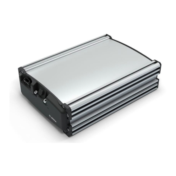
– Dimensions 179 x 317.75 x 90.5 mm – Weight approx. 3.5 kg – Sealed aluminum die-cast housing, built-in fan – CAN control interface, compatible with BOSCH MOTORSPORT e-GoKart system Illustration 19: System Context with the Charger Energy Storage CH 5-1.2 Electrical characteristics and maximum ratings... - Page 24 The proposed setup does not require additional grounding. Any additional grounding might lead to hazards or malfunction and is subject to agreement and validation with BOSCH MOTORSPORT. Thermal integration The Charger Energy Storage CH 5-1.2 does not require any additional active cooling. An integrated fan operates at higher temperatures.
- Page 25 Rack installation via 4x M6 screws at the bottom plate of the Charger Energy Storage 5-1.2. Screws shall only be mounted into clean screw threads of the BOSCH MOTORSPORT e- GoKart System components. No additional limitation concerning orientation and mounting angle Illustration 21: Mechanical dimensions and interfaces...
- Page 26 The normal operating voltage range is 36 to 54.6 V. At voltages above 54.6 V, an overvoltage condition will be detected in both the Charger Energy Stor- age CH 5-1.2 and attached Energy Storages ES 5-2.4. This detection will initiate a shut- down of the system. 26 / 60 e-GoKart_Powertrain__Young_Star__Manual Bosch Motorsport...
- Page 27 The batteries control the charge current depending on their state at any time. During Charge Charging time depends on the state of charge of the attached Energy Storages ES 5-2.4. The maximum charging current per pack is limited by the battery (default 10 A). Bosch Motorsport e-GoKart_Powertrain__Young_Star__Manual 27 / 60...
- Page 28 The Charger Energy Storage CH 5-1.2 contains self-diagnostic capabilities. Basic diagnostic information can be retrieved on the CAN. Illustration 23: Alarm state logic The device contains detections and protection from the following failures: – Overvoltage – Overcurrent / Short circuit / overload 28 / 60 e-GoKart_Powertrain__Young_Star__Manual Bosch Motorsport...
-
Page 29: Display Unit Ddu 18
– Components which show faulty behavior (e.g. tripping AC fuse) must not be used. – If any component shows a different behavior than stated in this document, the corres- ponding BOSCH MOTORSPORT representative has to be informed before continu- ation of use. - Page 30 The display performs best in a temperature range from 25 to 40°C. If the display temper- ature is below 25°C due to low environmental temperature, the display will be heated in- ternally. During heating-up the display performance may be slightly limited in response time. 30 / 60 e-GoKart_Powertrain__Young_Star__Manual Bosch Motorsport...
-
Page 31: Overall Integration Requirements Of E-Gokart System Components Into The Superior Vehicle Context
48 V net. The DC/DC converter provides a dedicated socket. # Screws to connect the wiring harness to the BOSCH MOTORSPORT e-GoKart System are in the responsibility of the CUSTOMER. BOSCH MOTORSPORT will propose appropriate screw descriptions based on the BOSCH MOTORSPORT e-GoKart System component in- terfaces. -
Page 32: Component Integration Requirements
5 | Overall Integration Requirements of e-GoKart System Components into the Superior Vehicle Context # At assembly or disassembly of the wiring harness to or from the interfaces of the BOSCH MOTORSPORT e-GoKart System, the used tightening torque shall not exceed the max- imum allowed torque, according to VDA specification. - Page 33 # The wiring harness shall not rub on neighboring parts. # Potential loads onto cover and/or bottom of the VCU MS 40 housing resulting from the mounting position in the vehicle shall be agreed on between the CUSTOMER and BOSCH MOTORSPORT.
- Page 34 # The Energy Storage ES 5-2.4 shall to be mounted with the designated T-nuts M6 (Bosch Rexroth part no. 3 842 530 321) and associated springs (Bosch Rexroth part no. 3 842 516 685), which are fixed in the notches of the housing, suchlike at the vehicle frame or at a...
- Page 35 – min. required conductor cross section 35 mm² – tightening torque: 18 to 25 Nm – max. allowed fixation torque: 25 Nm – max. allowed loosening torque: 32 Nm – max. allowed cable length up to next fixation: each max 300 mm Bosch Motorsport e-GoKart_Powertrain__Young_Star__Manual 35 / 60...
- Page 36 Illustration 26: Pulley mounting detail and example of pulley for toothed belts # The following figure shows measures that shall be considered in the pulley or coupling design. # For the transmission it is strongly recommended to use toothed belts. 36 / 60 e-GoKart_Powertrain__Young_Star__Manual Bosch Motorsport...
- Page 37 The Power Unit PU 5-10 is mounted by screws to the accessory bracket(s) in the vehicle. Screws to mount the Power Unit PU 5-10 with the accessory brackets are not in the BOSCH MOTORSPORT scope of delivery. # Only mounting points marked in Figure shall be used for the mounting of the Power Unit PU 5-10.
- Page 38 Power Unit PU 5-10 can be mounted adequately. Illustration 29: Mounting points of the PU 5-10 # The parallelism between vehicle support surface and the insulation bushing surface must be <0.05 mm. Illustration 30: Parallelism of customer engine block (Insulation bushing not necessary) 38 / 60 e-GoKart_Powertrain__Young_Star__Manual Bosch Motorsport...
- Page 39 The Display Unit DDU 18 can be mounted as stand-alone display to the handlebar or as an integrated display in the dashboard. The readability is depending on the mounting situation, especially the mounting angle. For mounting, there are 4 fixing points with M4 thread available. Bosch Motorsport e-GoKart_Powertrain__Young_Star__Manual 39 / 60...
- Page 40 # It shall be ensured that the tightening for mounting at the handlebar is designed in that way, that loosing of the screws is prevented over lifetime. Illustration 33: Mounting of faceplate onto the DDU 18 40 / 60 e-GoKart_Powertrain__Young_Star__Manual Bosch Motorsport...
-
Page 41: Wiring Harness Instruction / Build Up Chassis
Illustration 34: Kart chassis with fixed components 6.1 Implement the Components 6.1.1 48 V Wiring Harness Place a holder for the fuse on the black box with two M4 screws, washers and self-locking nuts. Illustration 35: 48 V wiring harness “Relay Mounting” Bosch Motorsport e-GoKart_Powertrain__Young_Star__Manual 41 / 60... - Page 42 They lead from the black box to the Power Unit PU 5-10 and the Energy Storages ES 5-2.4. Illustration 37: How to place the wires The following picture shows the wiring from the black box to the Power Unit PU 5-10, fixed after 50 to 100 mm. 42 / 60 e-GoKart_Powertrain__Young_Star__Manual Bosch Motorsport...
- Page 43 Place the cables close to the structure of the kart as shown in the following picture. Illustration 39: Cables placed close to the structure Connect 48 V wiring with Energy Storage ES 5-2.4 “1”. Illustration 40: How to connect the Energy Storage ES 5-2.4 Connect 48 V wiring with Energy Storage 5-2.4 “2”. Bosch Motorsport e-GoKart_Powertrain__Young_Star__Manual 43 / 60...
- Page 44 Implement the 12 V wiring harness in the chassis after you have installed the 48 V wiring harness. On the following figure you see the 12 V wiring harness. All wirings are marked with yellow labels. Illustration 42: 12 V wiring harness “delivery state” 44 / 60 e-GoKart_Powertrain__Young_Star__Manual Bosch Motorsport...
- Page 45 – ON / OFF switch “open end wiring” (See Figure) – Neutral / Drive switch “open end wiring” (See Figure) – SOC-LEDs “LED SOC_1”; “LED SOC_2”; “LED SOC_3”; “LED SOC_4” – Key switch “open end wiring” Bosch Motorsport e-GoKart_Powertrain__Young_Star__Manual 45 / 60...
- Page 46 After you put the relay housing on its fixation, you start with the left side of the wiring. To simplify the wiring, lead the 12 V harness above the 48 V wiring harness as shown in the following picture. 46 / 60 e-GoKart_Powertrain__Young_Star__Manual Bosch Motorsport...
- Page 47 Illustration 45: Charge CAN is connected to the HV wiring. Brake light and DC/CS are nor connected. – Charger CAN “charge_CAN” – Brake light “brake_sw” – DC/DC converter “DC/DC” Please fix the Anderson Connector direct with a screw on the chassis. Bosch Motorsport e-GoKart_Powertrain__Young_Star__Manual 47 / 60...
- Page 48 – ON / OFF switch “open end wiring” (see Figure) – Neutral / Drive switch “open end wiring” (see Figure) – SOC-LEDs “LED SOC_1”; “LED SOC_2”; “LED SOC_3”; “LED SOC_4” – Key switch “open end wiring” 48 / 60 e-GoKart_Powertrain__Young_Star__Manual Bosch Motorsport...
- Page 49 – Neutral: Wiring is not connected – Drive: Wiring is connected Neutral/Drive switch “open end wiring” Illustration 50: How to connect the wiring on the LED SOC-LEDs “LED SOC_1”; “LED SOC_2”; “LED SOC_3”; “LED SOC_4” – +-wiring: White – GND-wiring: Purple Bosch Motorsport e-GoKart_Powertrain__Young_Star__Manual 49 / 60...
- Page 50 6 | Wiring Harness instruction / Build up chassis Illustration 51: How to fix the wiring on the key switch Illustration 52: Key switch "open end wiring" Illustration 53: Power Unit PU 5-10-wiring fixed on the PU 5-10 50 / 60 e-GoKart_Powertrain__Young_Star__Manual Bosch Motorsport...
- Page 51 It is important that the wiring intersection is mounted at the end of the seat. – DDU 18 connector “SP/stear” – DDU 18 remote connector “rte_DDU” Illustration 55: DDU 18 connector should be fixed on the chassis via cable fixer. Bosch Motorsport e-GoKart_Powertrain__Young_Star__Manual 51 / 60...
- Page 52 Illustration 57: How to solder the wiring on the Boost Switch Please solder the open end wiring to the pins of the switch. – Purple: LED + – Green: LED GND – Grey: Switch – Black: Switch 52 / 60 e-GoKart_Powertrain__Young_Star__Manual Bosch Motorsport...
- Page 53 Illustration 58: How to solder the wiring on the Reverse Switch Please solder the open end wiring to the pins of the switch. – Brown: Switch – Yellow: Switch Illustration 59: Please fix the wiring on the steering wheel. Illustration 60: Fix the wiring under the metal sheet. Bosch Motorsport e-GoKart_Powertrain__Young_Star__Manual 53 / 60...
- Page 54 – Brake inductive sensor “p_brake” Illustration 62: Fixed connector in front of the pedal system 6.1.3 Acceleration pedal sensor The Acceleration pedal sensor should be mounted with the mark facing in wiring direc- tion. – Mark = Point 54 / 60 e-GoKart_Powertrain__Young_Star__Manual Bosch Motorsport...
- Page 55 Wiring Harness instruction / Build up chassis | 6 Illustration 63: Position of the Acceleration pedal sensor Illustration 64: Screws position Check: – Sensor mark position – Screws position Illustration 65: Acceleration pedal fixed Bosch Motorsport e-GoKart_Powertrain__Young_Star__Manual 55 / 60...
- Page 56 Illustration 66: Sensor turned in the final counter clockwise position After the sensor is fixed, you should check the sensor position. For the calibration, please use the BOSCH MOTORSPORT calibration adapter. The following picture shows the needed parts: Illustration 67: Multimeter with calibration adapter Please connect the calibration wiring harness with the digital multimeter.
- Page 57 The switches and LEDs are implemented in the right side wiring. All wiring harnesses are delivered with open end wiring. Please cut the wiring on the right length and fix the com- ponents in the metal sheet on the chassis. Bosch Motorsport e-GoKart_Powertrain__Young_Star__Manual 57 / 60...
-
Page 58: Vehicle Control Unit Vcu Ms
6.2 Vehicle Control Unit VCU MS 40 At the end of the wiring harness implementation, the Vehicle Control Unit VCU MS 40 can be fixed on the black box. Please use M3 screws with a washer and Loctite. 58 / 60 e-GoKart_Powertrain__Young_Star__Manual Bosch Motorsport... -
Page 59: Troubleshooting
Troubleshooting | 7 7 Troubleshooting For troubleshooting, please contact motorsport@bosch.de Bosch Motorsport e-GoKart_Powertrain__Young_Star__Manual 59 / 60... - Page 60 Bosch Engineering GmbH Motorsport Robert-Bosch-Allee 1 74232 Abstatt Germany www.bosch-motorsport.com...