Table of Contents
Advertisement
Available languages
Available languages
Quick Links
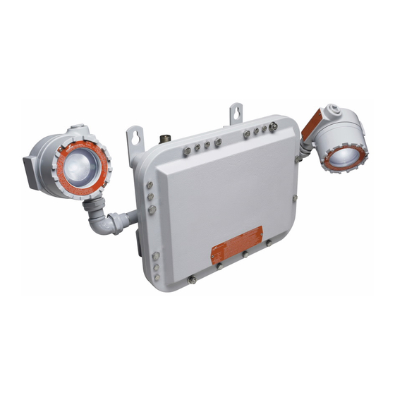
EMERGENCY LIGHTING PRODUCTS
ELPSM22 system, ELPSM22 EXS/EXD system, ELPSM20 power supply,
EVLAM2 luminaire
Installation & maintenance information
APPLICATION
The ELPSM22 emergency lighting system is designed to automatically provide
illumination to designated areas during failure or interruption of power to the normal
lighting system. The ELPSM22 is factory assembled and wired, and consists of one
(1) ELPSM20 power supply and two (2) EVLAM2 luminaires.
When properly installed, the following raintight ELPSM2 emergency lighting systems
are UL and cUL Listed for use in:
•
ELPSM20 power supply – Class I, Division 1, Groups B, C, D
•
ELPSM22 – Class I, Division 1, Groups B, C, D
•
Wet locations, Type 3R
•
Ambient temperature = 0°C to 40°C
•
Operating temperature code = T5
•
Maximum mounting height = 9.3 ft.
Exit signs are not UL/cUL Listed:
•
ELPSM22 (EXS/EXD)
•
ELPSM2 EVI EMERGENCY LIGHTING EQUIPMENT (EXIT SIGN)
•
ELPSM2 EVA GB EMERGENCY LIGHTING EQUIPMENT (GB [Group B] EXIT
SIGN)
All ELPSM2 emergency lighting systems without exit signs are suitable for use in
Class II, Division 1, Groups E, F, G and simultaneous presence hazardous (classified)
areas as defined by the National Electrical Code
The ELPSM20 power supply consists of a battery supply and battery recharging
system housed inside a hazardous area enclosure with all the circuitry to automatically
turn on emergency DC lighting equipment when the normal power supply fails. A
pilot light indicates when normal power is being supplied to the unit. A push-to-test
pushbutton switch is provided for periodic testing of the unit.
RATINGS
Input
Power supply
Output
Lamp model: LEDTronics
LEDG4BPF-1.5W-XIW-012V
(G4 2-pin base, 3000K)
Lamp fixtures
Lamp model: Westinghouse
33184 (G4 2-pin base, 3000K)
STORAGE ENVIRONMENT
The ELPSM2 luminaire and accessories must be stored in an ambient temperature
from 0°C to +40°C. This includes units that have already been installed and may be
powered down for extended periods of time (i.e. facility maintenance shutdowns).
Store in a dry location.
! IMPORTANT
Emergency lighting system should be installed, inspected, operated and
maintained by qualified and competent personnel.
IF 1875 • 03/19
®
.
IMPORTANT SAFEGUARDS – READ AND FOLLOW ALL SAFETY INSTRUCTIONS
• 120-277 VAC, 50/60 Hz
• 3.81 watts maximum
• 12 VDC; 0.33 amperes maximum
• 4 watts maximum for 1 ½ hours
• Input = 12 VDC, 1.5W
• Input = 12 VDC, 1.5W
SAVE THESE INSTRUCTIONS FOR FUTURE REFERENCE
Copyright
Detail indication logic is given below:
Status indication
*
* - *
**-**
***-***
****-****
Immediately after supply power is initiated, the indicating lamp will blink/pulse to
indicate that the unit is charging. Once installed with supply power, the ELPSM2
requires 15 hours to charge the battery. Once the unit has completed charging, the
indicating light will stop blinking and go to steady. Every six months, the unit will
automatically perform a 90 minute battery discharge test.
At the completion of the test, if it is determined not to have met the 90 minute
requirement, the indicating lamp will display circuit failure (3 blinks). At any time, if the
battery connection is not adequate, the indicating lamp will display a battery failure (2
blinks).
The EVLAM2 luminaire is a factory sealed assembly housing a single LED lamp/
reflector light source. ELPSM2 EVI and ELPSM2 EVA GB exit signs are factory sealed
with a single LED light source. Lamps are included with all equipment.
To avoid personal injury, electric shock and equipment failure:
1.
Do not use this equipment for other than intended use.
2.
The use of accessory equipment not recommended by the manufacturer
may cause an unsafe condition.
3.
Electrical power must be turned OFF and the battery must be
disconnected using the battery disconnect switch (if provided) before and
during installation and maintenance.
4.
Equipment should be mounted in locations where it will not readily be
subjected to tampering by unauthorized personnel.
5.
Do not mount near gas or electric heaters.
6.
In Class I areas, install and seal all equipment in accordance with the
National Electrical Code articles pertaining to hazardous (classified)
locations, plus any other applicable codes.
7.
Install only wiring systems with an equipment grounding conductor (which
may be the conduit system) to supply the ELPSM2.
8.
For safety in maintenance and servicing, a designated battery disconnect
switch and a designated supply circuit disconnect switch must be installed.
A main branch disconnect is suitable for disconnecting supply circuit.
9.
Free installation area of hazardous atmospheres before wiring.
10.
Observe all battery handling precautions contained herein.
11.
Hammers or prying tools must not be allowed to damage the flat joint
surfaces of the ELPSM20 power supply housing. Do not handle covers
roughly, or place them on surfaces that might damage or scratch the flat
joint surfaces.
2019, Eaton's Crouse-Hinds Division
®
Status description
Status definition
No light
AC power removed from circuit
Steady light (no blinks)
Fully charged or test in process
Light blinks once
Battery charging
Light blinks twice
Battery failure
Light blinks three times
Circuit failure
Light blinks four times
Lamp failure
Table 1
! WARNING
IF 1875
Page 1
Advertisement
Table of Contents

Related Manuals for Eaton ELPSM22


Summary of Contents for Eaton ELPSM22
- Page 1 No light AC power removed from circuit lighting system. The ELPSM22 is factory assembled and wired, and consists of one Steady light (no blinks) Fully charged or test in process (1) ELPSM20 power supply and two (2) EVLAM2 luminaires.
-
Page 2: Installation
Do not handle covers roughly, or place them on surfaces that might damage or scratch the flat joint surfaces. B. Attach and adjust EVLAM2 lighting luminaire(s) NOTE: If installing ELPSM22, equipment is already attached. Proceed to Step 8 to adjust equipment. Nut ‘B’... - Page 3 (See Warning below) If cable is utilized, a cable sealing fitting must be installed as required by This designated disconnect switch can be supplied as part of the ELPSM22 Sections 501.15 and 502.15 of the National Electrical Code plus any other emergency light (option S794 or option S854).
-
Page 4: Periodic Testing
Turn ON supply power to the ELPSM2 Light-Pak and turn ON the designated disconnect switch located next to the push-to-test button. Test replacement battery following Step 4 of “D. Complete installation.” IF 1875 • 03/19 Copyright 2019, Eaton’s Crouse-Hinds Division Page 4 ®... -
Page 5: Lamp Replacement
Install lens ring by turning clockwise until threads are fully engaged. All screw threads have been treated with a corrosion-resistant lubricant. Whenever disturbing threaded joints, re-lubricate the threads with Crouse-Hinds series STL thread lubricant. IF 1875 • 03/19 Copyright 2019, Eaton’s Crouse-Hinds Division Page 5 ®... -
Page 6: Maintenance Record
All statements, technical information and recommendations contained herein are based on information and tests we believe to be reliable. The accuracy or completeness thereof are not guaranteed. In accordance with Eaton’s Crouse-Hinds Division’s “Terms and Conditions of Sale,” and since conditions of use are outside our control, the purchaser should determine the suitability of the product for his intended use and assumes all risk and liability whatsoever in connection therewith. - Page 7 Información de instalación y mantenimiento APLICACIÓN Los detalles de la lógica de indicación se brindan a continuación: El sistema de iluminación de emergencia ELPSM22 está diseñado para brindar Indicación iluminación de manera automática a las áreas designadas durante la falla de estado...
-
Page 8: Instalación
B. Coloque y ajuste la(s) luminaria(s) de iluminación EVLAM2. Tuerca ‘B’ NOTA: Si al instalar el ELPSM22, el equipo ya está colocado. Vaya al paso 8 para ajustar el equipo. ! PRECAUCIÓN El brazo y la cabeza de la luminaria EVLAM2 están limitados a no más de 180º... - Page 9 Deje que el ELPSM2 cargue debajo de la potencia de línea durante 15 horas PAQUETE antes de iniciar cualquier prueba de la operación de emergencia de la luces. NOTA: Si al instalar el ELPSM22, la conexión de cables de suministro del equipo de BATERÍA LUZ INDICADORA...
-
Page 10: Reemplazo De Baterías
ENCIENDA la fuente de alimentación del Light-Pak ELPSM2 y ENCIENDA el interruptor de desconexión designado ubicado al lado del botón de prueba. Pruebe la batería de reemplazo siguiendo el paso 4 “D. Complete la instalación”. IF 1875 • 03/19 Copyright 2019, División Crouse-Hinds de Eaton Página 4 ®... - Page 11 Todas las roscas de tornillo han sido tratadas con un lubricante resistente a la corrosión. Cuando se desacomoden las juntas con rosca, vuelva a lubricar las roscas con el lubricante de roscas STL de la serie Crouse-Hinds. IF 1875 • 03/19 Copyright 2019, División Crouse-Hinds de Eaton Página 5 ®...
-
Page 12: Registro De Mantenimiento
Todas las declaraciones, la información técnica y las recomendaciones contenidas en este documento se basan en informaciones y pruebas que consideramos confiables. No se garantiza que las mismas sean precisas o estén completas. En conformidad con los “Términos y condiciones de venta” de la División Crouse-Hinds de Eaton y dado a que las condiciones de uso están fuera de nuestro control, el comprador debe determinar la idoneidad del producto para su uso previsto y asume todo riesgo y responsabilidad con relación al mismo. -
Page 13: Valeurs Nominales
IF 1875 Information sur l’installation et l’entretien APPLICATION Détails sur la logique des indications Le système d’éclairage d’urgence ELPSM22 est conçu pour offrir un éclairage Indicateur d’état Description de l’état Définition de l’état automatique pour certains emplacements en cas de défaillance ou d’interruption de Alimentation en c.a. - Page 14 égratigner les surfaces de joint plat. B. Fixer et ajuster un luminaire EVLAM2 REMARQUE : En ce qui concerne l’installation du système ELPSM22, le matériel est Écrou B déjà fixé. Passer à l’étape 8 pour procéder à un ajustement.
- Page 15 être exempt d’atmosphères dangereuses. D. Fin de l’installation REMARQUE : En ce qui concerne l’installation du système ELPSM22, le branchement Installer le dispositif de protection contre la corrosion CID101 (offert en pièce des câbles d’alimentation du matériel d’éclairage est déjà effectué. Procéder à l’étape 15.
-
Page 16: Remplacement De La Batterie
Mettre le système ELPSM2 Light-Pak sous tension et l’interrupteur d’isolement désigné situé à côté du bouton-poussoir d’essai à la position « ON » (marche). Tester la batterie de rechange en suivant l’étape 4 de la section D, « Fin de l’installation ». IF 1875 • 03/19 Division Crouse-Hinds d’Eaton, 2019 Page 4 ©... -
Page 17: Remplacement De La Lampe
Tous les filets de la vis ont été traités avec un lubrifiant résistant à la corrosion. En cas de perturbation des joints filetés, lubrifier à nouveau les filets avec du lubrifiant pour filetage STL de la série Crouse-Hinds. IF 1875 • 03/19 Division Crouse-Hinds d’Eaton, 2019 Page 5 ©... - Page 18 Toutes les déclarations et les informations techniques contenues dans le présent document sont basées sur des renseignements et des tests que nous croyons fiables. Leur exactitude ou leur exhaustivité ne sont pas garanties. Conformément aux conditions de vente de la Division Crouse-Hinds d’Eaton, et étant donné que les conditions d’utilisation sont hors de notre contrôle, l’acheteur doit déterminer si le produit convient à...