Table of Contents
Advertisement
Quick Links
User and Programming Manual
This document is intended for installers, set-up technicians and
IT professionals of the WaveLinx Wireless Connected Lighting System
Engage appropriate network security professionals to ensure all lighting control system hardware and servers
are secure for access.
Ensure IT professionals review the WaveLinx network architecture document found at the end of this manual.
Network security is an important issue. Typically, the IT organization must approve configurations that expose
networks to the Internet. Be sure to fully read and understand customer IT Compliance documentation.
Network
DISCLAIMER OF LIABILITY: Eaton assumes no liability for damages or losses of any kind that may arise from the
improper, careless, or negligent installation, handling or use of the products.
Security
IMPORTANT: This manual provides information on the installation and operation of WaveLinx Wireless Connected
Lighting System. For proper operation it is important to follow the installation instructions for each product/component.
ATTENTION
WaveLinx
Advertisement
Table of Contents

Related Manuals for Eaton WaveLinx


Summary of Contents for Eaton WaveLinx
- Page 1 Internet. Be sure to fully read and understand customer IT Compliance documentation. Network DISCLAIMER OF LIABILITY: Eaton assumes no liability for damages or losses of any kind that may arise from the improper, careless, or negligent installation, handling or use of the products.
-
Page 2: Table Of Contents
Step 4: Organizing Devices into Controlled Areas and Zones ....................27 Automatic Code Commissioning Operation ..........................34 Using the WaveLinx Mobile Application for Personal Control ......................35 Connecting with the Mobile Application as the Default Personal Control User ..............35 Assign a Favorite Area for Personal Control Users ........................36 Control the Lighting as a Personal Control User ........................37... - Page 3 Performing a System Restore ..............................114 Viewing Disclaimers and End User License Agreements ......................116 Viewing and Updating Firmware of the Wireless Area Controller and WaveLinx Devices ............116 Viewing Firmware of the Wireless Area Controller ....................116 Updating the Firmware/Software of the Wireless Area Controller ................117 Updating the Firmware of WaveLinx Devices ......................118...
- Page 4 The WaveLinx Wireless Connected Lighting System offers wireless, code-compliant control in a simple, easy to install and manage format. Designed with ease of use in mind, the WaveLinx wireless system installs and configures quickly to capture immediate energy and cost savings.
-
Page 5: Becoming Familiar With Wavelinx System Components
The Insight Manager and Lighting Xpert Insight software are optional for sites that want to have enterprise-level functionality. This functionality includes data centralization from networked WaveLinx Wireless Area Controllers, alarms and events management, exposing the data from the Wireless Area Controllers to third party system via BACnet and Public API (REST), user management and system backup. - Page 6 Eaton offers many options for luminaires pre-configured with a WaveLinx Integrated Sensor. The in-fixture sensor operates as a WaveLinx wireless communications router as well as an occupancy/vacancy sensor, closed loop daylight sensor, and power measurement point. The standard ambient integrated sensor is also...
- Page 7 0-10V lighting loads. Like the integrated sensor, the tilemounted sensor operates as a WaveLinx wireless communications router and functions as a closed loop daylight sensor within the WaveLinx Mobile Application. WaveLinx Ceiling Sensor...
- Page 8 Use the WaveLinx Wallstations to manually operate wirelessly connected loads. Models include standard WaveLinx Wallstations that connected to line voltage power and WaveLinx Battery Powered Stations that simplify retrofit installations. Operation includes button configuration support for scene selection, scene raise/lower, zone level, zone raise/lower, and scene and zone toggle capability.
-
Page 9: Bringing The System Online
WaveLinx User Manual Bringing the System Online The WaveLinx Wireless Connected Lighting System configures quickly to allow immediate energy savings. Use the steps in this section to: • Step 1: Confirm that installed devices are ready for configuration • Step 2: Complete initial construction grouping to prepare for mobile application use •... - Page 10 Controller. See page 135 for information on resetting Note: Daylighting is disabled until the fixture is the pairing.) assigned to an area using the WaveLinx Mobile Application. WaveLinx Ceiling Sensor LED may flash red once approximately every 10 This device does not have out-of-the-box functionality seconds indicating that the unit is powered.
-
Page 11: Step 2: Completing The Initial Construction Grouping
WaveLinx Mobile Application. 1: On the site floorplan, locate the WaveLinx Wireless Area Controller and identify the WaveLinx devices that should be paired to it. Sites designed to use multiple Wireless Area Controllers should identify the devices that belong to each controller so that they can be correctly paired with the appropriate Wireless Area Controller according to the design plan. - Page 12 WaveLinx User Manual 3: Press and release (1 second press) the PAIR button located on the rear panel of the Wireless Area Controller. The blue 802.15.4 LED on the Wireless Area Controller will blink at a rate of one blink per second to indicate the Wireless Area Controller is in pairing mode.
- Page 13 60 minutes if a device does not successfully pair with a Wireless Area Controller. Only unpaired devices will enter pairing mode on the power cycle. WaveLinx Integrated Sensor WaveLinx Tilemount Sensor Note: Standard WaveLinx Wallstations (line voltage powered) will also respond to this pairing technique. WaveLinx Industrial Integrated Sensor WaveLinx Outdoor Integrated Sensor www.eaton.com/wavelinx...
- Page 14 During the 60 minute pairing period, devices may exhibit paired behavior. It is possible to confirm successful WaveLinx device pairing by verifying that each device’s exhibits this behavior. It is also possible to confirm pairing after the pairing process is complete. Refer to the chart below to see a device’s expected behavior during initial pairing.
- Page 15 There is no immediate feedback that pairing was successful. Pairing will be verified through the mobile application in a later step. WaveLinx Wireless Outdoor Lighting Control Module Fixture dims briefly when paired then turns ON to a brighter light level and remains ON.
-
Page 16: Using The Mobile Application To Pair Devices
Using the Mobile Application to Pair Devices The WaveLinx Mobile Application may be used in the pairing process as an alternative to pressing the PAIR button on the Wireless Area Controller. Log in as the administrator user and open the menu to select the option to discover new devices, acknowledging the message that appears. -
Page 17: Operation Of Devices Within The Construction Grouping
WaveLinx User Manual During the pairing process, as devices join, a message may be briefly displayed on the screen. The mobile application will also display a device count of how many devices are paired with the Wireless Area Controller. Pairing Device count Device joined message Tap on the device count to open a link that shows a paired device list organized by device type. -
Page 18: Step 3: Connecting To The Mobile Application As The Administrator User
See “Modifying Existing User Accounts and Passwords” on page 105 for this procedure. 1: Download the latest version of the WaveLinx Mobile Application from Google Play™ or the App Store® and install it on a smartphone or tablet. The WaveLinx Mobile Application is compatible with devices running iOS 11+ or Android™ 7+ operating systems. - Page 19 Controller's MAC ID 4: Open the WaveLinx Mobile Application. The application may initially open in demo mode. Select the menu icon at the top-left corner of the screen, and then tap the demo mode button to switch to “real-time” (live) mode. After a few seconds, the Wireless Area Controller with the ID from the previous steps should appear on the screen.
- Page 20 WaveLinx User Manual 5: In the log in screen, enter the username and password for the administrator user (these are case sensitive). Default Username: WclAdmin • Default Password: wclAdmin • Select the option to save credentials to remember the login credentials automatically on this device for future connections and then select the log in button.
-
Page 21: Mobile Application Basic Familiarity
WaveLinx User Manual Mobile Application Basic Familiarity Before proceeding to the next step, become familiar with the basics of the WaveLinx Mobile Application. This section describes the terminology, icons, and basic navigation used in the mobile application. Areas Construction grouping automatically places all paired devices into a default construction area. - Page 22 In any area, controlled loads are organized into zones. A zone is a “group” of one or more lights, receptacles or other loads that are to be controlled together in the exact same way. The WaveLinx Mobile Application creates three zones by default. Zone 1 and 2 are automatically created for dimmable lighting devices.
- Page 23 WaveLinx User Manual Devices In the mobile application, each device type has a distinctive icon for quick identification. Device Icon WaveLinx Wireless Dimming Switchpack WaveLinx Integrated Sensor and Tilemount Sensor (standard ambient & tilemount) (bluetooth option) WaveLinx Industrial Integrated Sensor...
- Page 24 WaveLinx User Manual Icon colors indicate different device conditions. Icon Color Device Condition Device Green • The device is communicating and operational Device Gray or Red • The device is no longer communicating to the mobile application. • Upon reboot devices that do not communicate with the Wireless Area Controller after the reboot completes will remain gray.
- Page 25 WaveLinx User Manual For further information, tap any zone to see the devices that are assigned to the zone. Tap the desired zone View the controlled devices Devices that do not directly wire to a specific load (lighting or receptacles) such as wallstations and ceiling sensors will display in the in area section in the middle of the display screen.
- Page 26 WaveLinx User Manual Other icons There are many icons used to perform functions in the mobile application. Icon Functionality Displays menu options. Refreshes the current screen. From the main menu, discovers new devices. Indicates that the Wireless Area Controller is in pairing mode.
-
Page 27: Step 4: Organizing Devices Into Controlled Areas And Zones
1: Go to the location in the facility that will be programmed first. Open the WaveLinx Mobile Application and establish an administrator connection with the Wireless Area Controller. Once successfully connected, create a new area in the area list by tapping the + button on the right side of the screen. - Page 28 WaveLinx User Manual 3: (Optional) If the area needs additional zones beyond the provided defaults (dimmable lighting zones 1 and 2, and receptacle zone 3), tap the plus sign icon in the zones section to add a new zone. Type a descriptive name for the zone, and then select the zone type (dimmable, receptacle, or non-dimmable switched) other parameters may be left at defaults or modified for the application.
- Page 29 WaveLinx User Manual 4: Next assign the controlled load devices to the proper zones. While still in the area screen for the desired space, place the first controlled load device in the room into identification mode as described in this section. Once the device is identified, drag and drop the device into the desired zone.
- Page 30 How to initiate identification mode in controlled load devices: Device Identification Mode WaveLinx Integrated Sensor and For fixtures mounted at reasonable mounting heights, use a laser pointer or bright, focused beam WaveLinx Tilemount Sensor flashlight to trigger identification mode. Standing beneath the sensor, shine the light directly into the sensor lens for 3-4 seconds.
- Page 31 Industrial Integrated Sensor – Low Mount WaveLinx Wireless Dimming Switchpack Outdoor Integrated Sensor – High Mount WaveLinx Wireless Outdoor Lighting Control Modules Outdoor Integrated WaveLinx WaveLinx Wireless Sensor Wireless Outdoor Lighting – Low Mount...
- Page 32 • The LED on the button pressed may illuminate for approximately 3 seconds and devices in the construction area will respond to the button’s command. In the mobile application, the icon will begin flashing and will WaveLinx Wallstation Battery Powered move to the far left of the unassigned device list.* * Note: If multiple battery powered wallstations with the same button configuration are in the same area, rename each wallstation as it is assigned to allow for easy identification for the later programming steps.
- Page 33 WaveLinx User Manual 6: Once all devices are assigned, tap on the paired device count showing at the top of the area screen. Verify that the device types and counts match the actual quantity of devices that should be in that space.
-
Page 34: Automatic Code Commissioning Operation
WaveLinx User Manual Quick Links for Common Questions I am done assigning my devices to areas but I still have devices showing in my unassigned device list. What should I do? • See the answer on page 137 . During configuration, I found a device that was not powered. How do I get the device it to appear in the mobile application so that I can •... -
Page 35: Using The Wavelinx Mobile Application For Personal Control
WaveLinx User Manual Using the WaveLinx Mobile Application for Personal Control The WaveLinx Mobile Application allows occupants to have personal control of the lighting in their area. Use this section to: Connect to the Wireless Area Controller as a personal control user. -
Page 36: Assign A Favorite Area For Personal Control Users
Assign a Favorite Area for Personal Control Users It is possible to set each user’s mobile device to open the WaveLinx Mobile Application to a favorite area by default for quick and easy access to lighting and receptacle loads in their location. Note that this is stored on the device and not linked to the mobile account. Any user logged in to the same mobile device will share this favorite’s area. -
Page 37: Control The Lighting As A Personal Control User
WaveLinx User Manual Control the Lighting as a Personal Control User The mobile application’s personal control feature allows the occupant of the space to control lighting in their location within defined programmed parameters. Occupancy/vacancy sensing, daylighting, and demand response settings will define the range within which the occupant can: Raise and lower the light level of all controlled zones in the area. -
Page 38: Customizing The Automatic Code Commissioning Programming
WaveLinx User Manual To issue pre-programmed scenes, use the controls in the scene menu. Tap to open scene selection screen Tap on desired scene to activate pre-programmed scene levels Quick Links for Common Questions When I log in as the personal control user, not all of the scenes are showing. Why is this happening? See the answer on page 137 . - Page 39 To modify the name of an area, zone or device: Step 1: Open the WaveLinx Mobile Application and establish a connection with the Wireless Area Controller as the administrator user. Step 2: In the areas list, select the area that will be modified. If modifying a zone name, select the zone. If modifying a device, locate the device in either the area device section, or within a zone‘s device section.
-
Page 40: Modifying Scene Response
Modifying Scene Response The WaveLinx system allows for sixteen programmable scenes per area. These scenes are labeled scene 0 through scene 15. Each scene is pre-programmed for a light level or ON/OFF response to allow for functionality from occupancy sensors and wallstations once devices have been PAIRED in the construction group or assigned to an area. - Page 41 WaveLinx User Manual Step 3: At the top-right of the area screen, tap the scene menu to display the area’s scenes. Select the scene menu to open the area’s scenes Step 4: In the area’s scene list, locate the row for the desired scene. Tap the arrow that is at the far-right in the desired row to open the scene for modification.
- Page 42 WaveLinx User Manual Step 5: Once in the screen, modify the scene with the desired options: Select whether the adjustment will be “live” to see changes in real-time or “static” if light levels should not change during the • modification.
-
Page 43: Modifying Zone Response
0-10V fixtures. By default, the WaveLinx system starts with all dimmable zones set to a minimum level of 0% and a maximum level of 90%. These settings may be changed at any time by the administrator user. - Page 44 WaveLinx User Manual Step 3: In the area screen, select the desired zone. Select zone to modify Step 4: In the zone screen, select the pencil icon in the upper-right corner to open the edit function. Select the pencil icon to edit the zone...
-
Page 45: Modifying Zone Operational Mode
Before beginning, assign the switched load to the same zone as the dimmed lighting that it needs to operate with. Step 1: Open the WaveLinx Mobile Application and establish a connection with the Wireless Area Controller as the administrator user. - Page 46 WaveLinx User Manual Step 3: In the area screen, select the desired zone. Select zone to modify Step 4: In the zone screen, select the pencil icon in the upper-right corner to open the edit function. Select the pencil icon to edit the zone Step 5: Use the drop down selection to choose the operation mode and settings.
- Page 47 WaveLinx User Manual Use the operation mode drop down Select the desired Save the settings operation mode Zone Operational Mode Parameter Details: First On/Last Off: • If the zone is OFF , switched loads in the zone will respond ON when any command level other than 0% is received. If the zone is ON, switched loads within the zone will turn OFF when the zone reaches a 0% (OFF) light level.
-
Page 48: Modifying Wallstation Button Response
Modifying Wallstation Button Response Once assigned to their controlled area, WaveLinx Wallstations operate with default functionality. The following charts describe the default wallstation button response for the standard WaveLinx Wallstations (line voltage powered) and for the battery powered WaveLinx Wallstations. -
Page 49: Battery Powered Wallstation Default Button Response
WaveLinx User Manual Battery Powered Wallstation Default Button Response WB2L-x Button #1: Scene 1 Scene 1 Scene 1 Scene 1 Scene 1 Scene 1 Scene 1 Full Lights Full Lights Full Lights Scene 1 Scene 1 Scene 1 Half Lights... -
Page 50: Changing Default Button Response
To change the response of a wallstation button: Step 1: Open the WaveLinx Mobile Application and establish a connection with the Wireless Area Controller as the administrator user. Step 2: In the areas list, select the area that contains the wallstation to be modified. - Page 51 WaveLinx User Manual Step 4: In the wallstation screen, ensure that the faceplate configuration shown matches the faceplate of the wallstation model being configured. For standard line voltage powered wallstations only, if necessary, select the correct configuration from the drop down list.
- Page 52 WaveLinx User Manual Step 6: Repeat steps 4 and 5 for additional buttons on the selected wallstation. Repeat this procedure for additional wallstations in the space or use the copy function described in the next section. Wallstation Parameter Definitions: No action: The button will not perform any command if pressed.
-
Page 53: Copying Wallstation Programming To Other Wallstations
Step 1: Open the WaveLinx Mobile Application and establish a connection with the Wireless Area Controller as the administrator user. Step 2: In the areas list, select the area that contains the wallstation that has already been programmed with the desired settings. - Page 54 WaveLinx User Manual Step 4: In the wallstation screen, select the pencil icon to open the edit feature. Tap in the name field and type a unique name for this wallstation that will be easily recognized. Touch the save button to save the change and then tap the back button to return to the area list.
- Page 55 WaveLinx User Manual Step 6: In the edit screen, tap the drop down in the copy section and select the name of the programmed wallstation. If desired, type a name for the new wallstation and then tap save. If desired, give...
-
Page 56: Additional Wallstation Information
WaveLinx User Manual Additional Wallstation Information There are some helpful items available in the mobile application to assist with wallstation identification and battery monitoring. Blink to Identify • In an area that has a large quantity of the same model of standard line voltage powered wallstations, use the mobile application’s blink to identify feather to identify which wallstation is which. -
Page 57: Modifying Occupancy Sensor Response
To modify the occupancy set response and controlled zones: Step 1: Open the WaveLinx Mobile Application and establish a connection with the Wireless Area Controller as the administrator user. Step 2: In the areas list, select the area that contains the desired occupancy set. - Page 58 WaveLinx User Manual Step 3: In the area screen, select the gear icon in the upper-right corner to open the area menu and then select the occupancy set option. Select the gear icon to open the area menu Select the occupancy sets option Step 4: Next, select the desired occupancy set to modify.
- Page 59 WaveLinx User Manual Step 5: In the attributes screen, modify the desired settings. Note that this screen also indicates if any sensor in the occupancy set is currently detecting motion. View real-time status of the sensor • Dark white icon-occupied •...
- Page 60 WaveLinx User Manual Step 6: Next, view the zone and sensors screens to review the devices that are affected by this occupancy set or to make a changes to the controlled zones or assigned sensors. Remove or add controlled zones by dragging and dropping the zone icon between the controlled zones list and the area zones lists. Zones •...
-
Page 61: Viewing And Adjusting Individual Sensor Settings
Step 2: In the areas list, select the area that contains the desired occupancy sensor. Step 3: In the area screen, locate the desired device. WaveLinx Ceiling Sensors will appear in the in area device section while fixture integrated sensors will appear within the assigned zone. Tap the desired device to open the configuration screen. -
Page 62: Defining Additional Occupancy Sets
WaveLinx User Manual Step 4: Modify or view the desired settings within the sensor screen. View real-time status of the sensor: • Dark blue icon-occupied • Light blue icon - vacant View currently assigned occupancy set hold time Modify sensor setting per... - Page 63 To create a new occupancy set: Step 1: Open the WaveLinx Mobile Application and establish a connection with the Wireless Area Controller as the administrator user. Step 2: In the areas list, select the area that requires the additional occupancy sets.
- Page 64 WaveLinx User Manual Step 4: Select the plus sign icon to create an additional occupancy set, and then select one of the occupancy sets to begin configuration. Tap on one of the occupancy Tap the plus sign icon to add another occupancy set.
- Page 65 WaveLinx User Manual Step 6: While still in the occupancy set screen, tap the zone icon. Touch and drag the zones to be controlled into the controlled zones section. Touch and drag zones that should not be controlled into the area zones section.
-
Page 66: Associating Occupancy Sets For Overlapping Or Cascading Control
To associate the occupancy set: Step 1: Open the WaveLinx Mobile Application and establish a connection with the Wireless Area Controller as the administrator user. Step 2: In the areas list, select the desired area. - Page 67 WaveLinx User Manual Step 4: Select the desired occupancy set. As a general rule, start by modifying the occupancy set that needs to receive signals from other occupancy sets to accomplish the desired overlapping or cascading control functionality. In the occupancy set screen’s attributes, tap the link on the right side of the screen to navigate to the associated occupancy sets.
- Page 68 WaveLinx User Manual Step 6: Review the changes to verify that all desired occupancy sets have been associated. Note that the occupancy set screen should show the quantity of sets associated. In this example, any time occupancy is detected by occupancy sets A, B, or C, the occupancy signal will be forwarded to trigger occupancy set D.
- Page 69 WaveLinx User Manual With this programming, as an occupant enters the walkway zone D, only zone D will initially respond. As the occupant enters cubicle zone A, the lighting will respond in zone A. If the occupant remains in zone A, then zone A and the walkway zone D will remain ON, even if there is no further motion in zone D.
-
Page 70: Deleting Occupancy Sets
To delete an occupancy set: Step 1: Open the WaveLinx Mobile Application and establish a connection with the Wireless Area Controller as the administrator user. Step 2: In the areas list, select the area that contains the desired occupancy set. -
Page 71: Modifying Light Levels For Daylight Sensors
Open Loop Daylighting The WaveLinx battery operated ceiling sensors are used for open loop daylight control in interior spaces. The WaveLinx Wireless Outdoor Lighting Control Module is used for open loop daylight control in exterior spaces. With open loop daylight control, the sensor is placed in a spot that is optimal for sensing daylight contribution while minimizing the sensor’s view of the electric light in the controlled area. -
Page 72: Modifying Closed Loop Daylighting Control
Step 1: Open the WaveLinx Mobile Application and establish a connection with the Wireless Area Controller as the administrator user. - Page 73 WaveLinx User Manual Step 3: In the area screen, tap on the zone that the controlled fixture is assigned to. If there are multiple fixtures in the zone, identify the correct device by using one of the following methods: Method 1: Using a laser pointer or flashlight, stand beneath the fixture and shine the laser pointer directly into the lens of the sensor for •...
- Page 74 WaveLinx User Manual Step 5: In the area screen, select the gear icon in the upper-right corner to open the area menu and then select the daylight set option. Select the gear icon to open the area menu Select the daylight sets option Step 6: Tap on the icon for closed loop daylighting.
- Page 75 Calibrating and Modifying Light Levels for Closed Loop Daylight Sensors In the WaveLinx system, standard ambient and industrial fixture integrated sensors as well as tilemount daylight sensors use closed loop daylighting to directly control the physically connected load. Unlike occupancy sets, closed loop daylight sensors cannot be grouped into a single daylight set.
- Page 76 WaveLinx User Manual Step 3: In the area screen, select the gear icon in the upper-right corner to open the area menu and then select the daylight set option. Select the gear icon to open the area menu Select the daylight sets option Step 4: Tap on the icon for closed loop daylighting.
- Page 77 WaveLinx User Manual Step 5: Use the slider bars to adjust the electric light to the desired level for each controlled fixture. Verify that the level is correct by placing the light meter on the surface beneath each of the controlled fixtures, ensuring that the reading is within the desired range. If the light level is still too bright when electric lighting is fully dimmed, use available shading to adjust the amount of incoming daylight or postpone calibration until the amount of incoming daylight has decreased.
- Page 78 WaveLinx User Manual Step 7: Repeat these steps for other areas as needed for the application. Calibrating and Modifying Light Levels for a Single Closed Loop Daylight Sensors It is also possible to adjust the closed loop settings for an individual sensor. Open the area that the fixture is located in and then locate and tap on the icon for the identified fixture load.
- Page 79 Calibrating and Modifying Light Levels for Exterior Closed Loop Daylight Sensors In the WaveLinx system, outdoor fixture integrated sensors use closed loop daylighting to directly control the physically connected load. Each daylight sensor is automatically assigned to a unique daylight set.
- Page 80 WaveLinx User Manual Step 3: In the area screen, select the gear icon in the upper-right corner to open the area menu and then select the daylight set option. Select the gear icon to open the area menu Select the daylight sets option Step 4: Tap on the icon for closed loop daylighting.
-
Page 81: Configuring Open Loop Daylighting Control
Configuring Open Loop Daylighting Control This section focuses on the use of open loop daylighting control. In the WaveLinx system, open loop daylighting is not part of the automatic code commissioning operation and must be specifically configured. This process is discussed in detail for both interior and exterior open loop daylighting applications. - Page 82 OFF should be between 250 to 375 lux for best results.) Step 2: Open the WaveLinx Mobile Application and establish a connection with the Wireless Area Controller as the administrator user. Step 3: In the areas list, select the area to calibrate.
- Page 83 WaveLinx User Manual Step 6: Select the gear icon in the upper-right corner to open the area menu and then select the daylight set option. Select the gear icon to open the area menu Select the daylight sets option Step 7: Tap on the icon for open loop daylighting and then tap the plus sign to create a new open loop daylight set. Tap on the new daylight set to open it.
- Page 84 WaveLinx User Manual Step 8: At the top of the screen, tap the pencil icon and enter a descriptive name for this daylight set and save it. Tap the edit icon Type a descriptive name Tap save Step 9: Tap the output icon. Locate the zone or zones that should respond to this daylight sensor. Although fixtures (green icons) may be individually assigned, the use of zones (blue icons) is recommended to simplify programming.
- Page 85 WaveLinx User Manual Step 10: Next, tap on the sensor icon. If multiple ceiling sensors are listed in the available sensors list, locate the sensor with the name/ descriptor identified earlier in this procedure. Drag and drop the identified sensor into the assigned sensor section.
- Page 86 The WaveLinx wireless outdoor control module is hardcoded for ON at dusk / OFF at dawn operation based on optimal performance factors for outdoor application. These settings cannot be modified. Lighting will turn OFF if the light level has exceeded 65 lux for a period of 180 seconds (3 minutes).
- Page 87 WaveLinx User Manual Step 2: In the areas list, select the area to configure. • Step 3: If multiple wireless outdoor lighting control modules are within the area, decide which module will be used for daylighting. In the mobile application area screen, tap on the zone that contains the chosen wireless outdoor lighting control module. If unsure of which device it is, double tap the first device’s icon to place it in blink to identify mode.
- Page 88 WaveLinx User Manual Step 4: In the area screen, select the gear icon in the upper-right corner to open the area menu and then select the daylight set option. Select the gear icon to open the area menu Select the daylight sets option Step 5: Tap on the icon for open loop daylighting and then tap the plus sign to create a new open loop daylight set.
- Page 89 WaveLinx User Manual Step 6: At the top of the screen, tap the pencil icon and enter a descriptive name for this daylight set and save it. Tap the edit icon Type a descriptive name Tap save Step 7: Tap the output icon. Locate the zone or zones that should respond to this daylight sensor. Although fixtures (green icons) may be individually assigned, the use of zones (blue icons) is recommended to simplify programming.
- Page 90 WaveLinx User Manual Step 8: Next, tap on the sensor icon. In the available sensors list, locate the sensor with the name/ descriptor identified earlier in this procedure. Drag and drop the identified sensor into the assigned sensor section. Tap sensor...
-
Page 91: Adding Schedule Events To The Control Strategy
WaveLinx User Manual Tap calibration Use the slider bar to adjust dimming response Test mode will be enabled Quick Links for Common Questions My exterior lighting does not all respond ON or OFF at the same time. Why is this occurring? See the answer on page 140. - Page 92 To enable and modify a schedule event: Step 1: Open the WaveLinx Mobile Application and establish a connection with the Wireless Area Controller as the administrator user. Step 2: In the area list screen, select the schedule option.
- Page 93 WaveLinx User Manual Step 4: Tap the pencil icon at the top-right of the schedule event screen to open the edit feature. Type a descriptive name for the schedule event, select the event type (astro clock or custom time), select the desired parameters and then tap the save button to continue.
- Page 94 WaveLinx User Manual Step 6: In the action screen, select the desired event action and area for the command. Select other parameters based on the command chosen. Once completed, touch the save button. Select the event command Select the area...
-
Page 95: Basic Schedule Event Screen Information
Once released, the lighting returns to the correct level for the active command. Use the WaveLinx Mobile Application to adjust demand response reduction levels and to exempt zones from responding. -
Page 96: Modifying Demand Response Behavior
Modifying Demand Response Behavior To modify or test demand response behavior: Step 1: Open the WaveLinx Mobile Application and establish a connection with the Wireless Area Controller as the administrator user. Step 2: In the areas list, select the first area to modify. -
Page 97: Testing Demand Response
Testing Demand Response The WaveLinx Mobile Application contains a built-in test feature for verifying that demand response levels are set correctly. When activated, all areas with zones assigned to respond to demand response will respond with the defined reductions. - Page 98 WaveLinx User Manual Step 3: Select the gear icon in the upper-right corner to open the area menu screen, and then in the area menu, select the demand response option. Select the gear icon to open the area menu Select the demand response option Step 4: Switch the ON/OFF status button to the ON position to place the system in demand response test mode.
-
Page 99: Performing Administrator Tasks
View disclaimers and license agreements • Firmware administration • View and update firmware/software of the Wireless Area Controller • View or update firmware of WaveLinx devices • Advanced network administration • Administer Wi-Fi access point settings • Administer other Wi-Fi settings •... -
Page 100: Logging Into The Wireless Area Controller Webpages
Firefox version 63 or higher. Step 2: Go to the location of the Wireless Area Controller. On the front plate of the Wireless Area Controller below the blue Eaton LED, locate the label with the MAC ID. Make note of the MAC ID shown. - Page 101 WaveLinx User Manual Step 4: Open the web browser. In the web browser address bar, enter the IP address of the Wireless Area Controller. (The default IP address if connecting through the onboard wireless access point is 192.168.100.1.) The first time the Wireless Area Controller is accessed, the browser may display message windows regarding the site security certificate.
-
Page 102: Setting The System Location, Time, Date And Time Zone
WaveLinx User Manual The internal webpage will open and display the system page. Enter the administrator username and password Successful log in displays the system page Setting the System Location, Time, Date and Time Zone To ensure schedule event accuracy, set the location, time, date, and time zone in the controller. The location is used for astronomic clock sunset and sunrise times. - Page 103 WaveLinx User Manual Select use auto location Select auto detect location Allow location access Verify success Manually review coordinates Method 2: If the computer or device being used to connect to the Wireless Area Controller is not connected to a network or does not support the GPS location feature, the coordinates may be manually entered.
- Page 104 WaveLinx User Manual Step 3: In the system page, review the current time and date at the top of the screen. If the time and date are not correct, first, make sure the computer’s time and date are correct and then select the option to manually set date and time. Next, use the time zone drop down to select the proper time zone.
-
Page 105: Managing User Accounts And Passwords
The Wireless Area Controller determines user access and permissions by associating the user accounts with different roles. For the purposes of a stand-alone WaveLinx Wireless Area Controller, only two roles will be used: System Administrator Role: A user defined as a system administrator will have access to all functions within the WaveLinx Mobile •... -
Page 106: Adding A New User Account
WaveLinx User Manual Step 3: Make the necessary changes to the role, username or password. If changing the password, the password must be between 8 and 16 characters and must contain at least 1 upper case letter, 1 number and 1 special character. The special characters that may be used are "#$'()*,-./:;<=>?@[]^_`{|}~. -
Page 107: Deleting A User Account
WaveLinx User Manual Step 3: Select the role, user name and password for the new account per the details shown below. Then select the option to create user to save the new user account. Verify that a success message appears at the top of the accounts screen. -
Page 108: Using The Backup And Restore User Accounts Option
WaveLinx User Manual Step 3: In the message screen that appears, select the delete button to confirm the account deletion. Confirm the deletion Verify success message at the top of the accounts page Using the Backup and Restore User Accounts Option Once user accounts are defined, the accounts may be backed up. - Page 109 Step 4: After the file transfer completes, verify that the file is in the computer’s downloads directory. The file name will reflect that it is a user database backup and the date that the backup was created. Move the file to a designated directory for WaveLinx user database backups (optional).
-
Page 110: Restoring User Accounts From A Backup
WaveLinx User Manual Restoring User Accounts from a Backup To restore the user accounts from a backup: Step 1: Establish a connection from the computer and the Wireless Area Controller as the system administrator user. Step 2: In the accounts page, scroll down the screen, and then select the option to browse to the location of a user backup file. Navigate to and then select the user backup file to restore. -
Page 111: Using The Mobile Application To Change Passwords
Using the Mobile Application to Change Passwords Use the WaveLinx Mobile Application as an alternate method of changing user passwords. While any user account password may be changed using this method, only a user logged in as a system administrator may make the changes. -
Page 112: Renaming The Wireless Area Controller
WaveLinx User Manual Renaming the Wireless Area Controller Each Wireless Area Controller has a default name that will appear in the WaveLinx Mobile Application. It is possible to change this name through the internal webpages. To change the Wireless Area Controller default name: Step 1: Establish a connection from the computer and the Wireless Area Controller as the administrator user. - Page 113 Step 4: After the file transfer completes, verify that the file is in the computer’s downloads directory. The file name will reflect the Wireless Area Controller name and the date that the backup was created. Move the file to a designated directory for WaveLinx backups (optional).
-
Page 114: Performing A System Restore
WaveLinx User Manual Performing a System Restore Restore the system at any time from a previously created backup file. A backup may also be restored to a replacement Wireless Area Controller if necessary. During restoration, devices will remain in their current state until the restoration is complete and they have rejoined the wireless network. - Page 115 WaveLinx User Manual Step 4: Next, select the restore option. This process may take several minutes. Once complete, a successful restore message will be displayed. Select the restore option Verify success message At this point, it is possible to disconnect from the webpage. The restoration process may take approximately 45 minutes to propagate to all connected devices and may take approximately an additional 45 minutes for devices to operate with the restored programming.
-
Page 116: Viewing Disclaimers And End User License Agreements
Viewing and Updating Firmware of the Wireless Area Controller and WaveLinx Devices It is important to keep the Wireless Area Controller and installed WaveLinx devices current with firmware updates to ensure functionality and security. Check for updates by registering and logging in on Eaton’s connected building portal, mycb.eaton.com and navigating to the firmware page. -
Page 117: Updating The Firmware/Software Of The Wireless Area Controller
To perform an update to the Wireless Area Controller firmware/software: Step 1: Download the firmware file from Eaton’s connected building portal, mycb.eaton.com and save it to the computer being used to perform the update. If the file is in a .zip format, unzip the files to a known location. The filename should appear as otaUgrade.tgz. -
Page 118: Updating The Firmware Of Wavelinx Devices
Step 6: The update process takes approximately 5 minutes during which the system may display a warning, and then will reboot and display the log in page. If the Wireless Area Controller is in a location that is visible, the Eaton LED or other LEDs may flash during the firmware update process. - Page 119 WaveLinx User Manual Manually Updating WaveLinx Device Firmware To manually update WaveLinx device firmware: Step 1: Establish a connection from the computer and the Wireless Area Controller as the administrator user. Step 2: Next, navigate to the firmware page. Select the option to get all devices. When prompted, enter the administrator username and password to log in to the lighting engine.
- Page 120 Once one device finishes, the controller will move on to the next device and will continue until all devices are updated. If the Wireless Area Controller is in a location that is visible, the Eaton LED or other LEDs may flash during the firmware update process.
-
Page 121: Advanced Network Administration
WaveLinx User Manual Firmware screen Enable allow auto upgrade Quick Links for Common Questions What will my devices do during a firmware update? See the answer on page 139. • Advanced Network Administration Additional administrator settings are available for advanced network functions. This includes: Changing Wi-Fi access point settings •... -
Page 122: Changing Wi-Fi Settings
WaveLinx User Manual Network page Reboot for changes to take effect Enter wireless access point details Select update Changing Wi-Fi Settings The Wireless Area Controller may be connected to the facility’s building WLAN for wireless communications. If the Wireless Area Controller is to be used in this manner, in the network page, enter the desired WLAN SSID, the authentication and encryption methods used by the WLAN, and the password information that has been provided by the network administrator. -
Page 123: Changing Ethernet Settings
Custom Certificates WaveLinx uses Eaton provided default SSL certificates that are installed with the system to certify Wireless Area Controller communication to mobile devices and computers. The provision has been made to allow for future support of other custom certificates. This custom certification option feature is not currently operational and should not be used without discussion with Eaton’s technical support team. -
Page 124: Rebooting The Wireless Area Controller
Use the WaveLinx Mobile Application to view the current application version. Step 1: On the user’s mobile device, open the WaveLinx Mobile Application. The mobile application does not need to be connected to the Wireless Area Controller to view the version information. -
Page 125: Updating The Mobile Application
Step 2: Open the WaveLinx Mobile Application and establish a connection with the Wireless Area Controller as the administrator user. Step 3: From the WaveLinx Mobile Application, select the menu icon. Tap on the option to enable pairing and then tap on the OK button to proceed. - Page 126 60 minutes if a device does not successfully pair with a Wireless Area Controller. Only unpaired devices will enter pairing mode on the power cycle. WaveLinx Integrated Sensor WaveLinx Industrial Integrated Sensor WaveLinx Outdoor Integrated Sensor Note: Standard WaveLinx Wallstations (line voltage powered) will also respond to this pairing technique. WaveLinx Tilemount Sensor www.eaton.com/wavelinx...
- Page 127 • On the standard WaveLinx Wallstation (line voltage powered), the LED on the button pressed should flash slowly for approximately 10 seconds. • On the WaveLinx Battery Powered Wallstation, the red LED below the buttons may flash briefly when the proximity sensor detects someone near and may flash intermittently during the pairing process. No other feedback from button LEDs will occur.
- Page 128 WaveLinx User Manual Step 5: Wait a few minutes to give the system enough time to find the device. The device may display a message briefly on the mobile application when it joins the paired construction group. The device will show in the construction group if the message was missed.
- Page 129 WaveLinx User Manual Step 7: Next, open the originally programmed device. For load devices, open the device’s control zone. For wallstations or ceiling sensors, locate the device in the in area section. Note that the icon for the device may be gray or red indicating that the device has lost communication.
-
Page 130: Using The Wireless Area Controller Pair Button Advanced Functionality
Using the Wireless Area Controller PAIR Button Advanced Functionality The WaveLinx Wireless Area Controller PAIR button is used during the initial construction grouping pairing process. It also allows for some advanced functionality to reset administrator and Wi-Fi user names and passwords, and restore factory defaults. These functions should be... -
Page 131: Common Questions
Unexpected Condition Resolution Steps Wireless Area Controller • The blue Eaton logo LED is • Ensure the unit is connected to a PoE switch or injector for power. not illuminated. • Try to perform the PAIR function. If the PAIR operation works and the unit appears operational, WAN LED •... - Page 132 WaveLinx User Manual WaveLinx Industrial Integrated No LED in the sensor window • Verify that the fixture’s power source is connected and powered from the circuit breaker. Sensor and the connected fixture is • Verify that the sensor is fully seated on the fixture mounting.
- Page 133 WaveLinx User Manual WaveLinx Battery Powered When a button is pressed, no • Out-of-the-box, this is the correct behavior. Wallstations button LEDs illuminate. When my hand is in proximity • Verify that the batteries are installed properly for the wallstation and that they are fully charged.
- Page 134 WaveLinx User Manual To remove a single device For a single device, select the device to open the device screen, then select the trash can icon and confirm the deletion. Then, pair the device with the correct Wireless Area Controller.
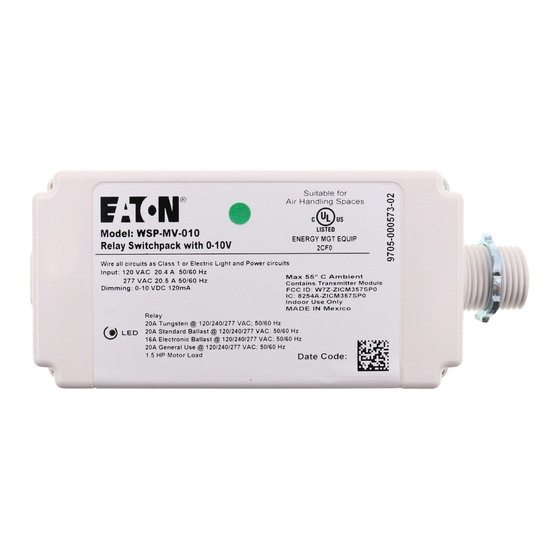
- Page 135 WaveLinx User Manual Device Type How to remove pre-existing pairing WaveLinx Wireless Dimming Switchpack Cycle the power to (switch OFF and then ON) the device’s circuit six times. This removes pairing for ALL devices (WSP-MV-010: 120-277VAC model) of this type on the affected circuit.
- Page 136 WaveLinx User Manual WaveLinx Wireless Outdoor Lighting Control Module Cycle the power to (switch OFF 2 seconds and then ON 4 seconds) the device’s circuit twenty times. This removes pairing for ALL devices of this type on the affected circuit.
- Page 137 WaveLinx User Manual I am done assigning my devices to areas but I still have devices showing in my all unassigned devices list. What should I do? If this is the only Wireless Area Controller in the facility, a device may have been added that is not shown on the plans. Connect to the Wireless Area Controller using the mobile application.
- Page 138 WaveLinx User Manual When I log in as the personal control user, not all of the scenes are showing when I go to the scene screen. Why is this happening? It is possible that the administrator of the system has hidden the scene during the configuration process. If this was done in error, log in to the system as the administrator user, and then select the area to modify.
- Page 139 WaveLinx User Manual I am not using demand response. How do I disable it? There is no need to disable the demand response feature. If a demand response system is not connected, the system will not trigger a demand response command unless placed into test mode through the mobile application. The test mode may be cancelled through the mobile application or will time-out automatically after 30 minutes if it is triggered in error.
- Page 140 82 to recalibrate the sensors. If WaveLinx Wireless Outdoor Lighting Control Modules are being used, it is possible to have one sensor control daylighting for the fixture it is mounted on or for a defined group of fixtures. If fixtures are not responding at the same time to daylighting commands, they may be assigned to different daylight sets.
- Page 141 Warranties and Limitation of Liability Please refer to www.eaton.com/LightingWarrantyTerms for our terms and conditions. Garanties et limitation de responsabilité Veuillez consulter le site www.eaton.com/LightingWarrantyTerms pour obtenir les conditions générales. Garantías y Limitación de Responsabilidad Visite www.eaton.com/LightingWarrantyTerms para conocer nuestros términos y condiciones.