
Related Manuals for Canon Additional Finisher Tray-C1

Summary of Contents for Canon Additional Finisher Tray-C1
- Page 1 Service Manual Finisher, Sorter, DeliveryTray Additional Finisher Tray-C1 Sep 14 2005...
- Page 3 Canon will release technical information as the need arises. In the event of major changes in the contents of this manual over a long or short period, Canon will issue a new edition of this manual.
- Page 4 Introduction Symbols Used This documentation uses the following symbols to indicate special information: Symbol Description Indicates an item of a non-specific nature, possibly classified as Note, Caution, or Warning. Indicates an item requiring care to avoid electric shocks. Indicates an item requiring care to avoid combustion (fire). Indicates an item prohibiting disassembly to avoid electric shocks or problems.
- Page 5 Introduction The following rules apply throughout this Service Manual: 1. Each chapter contains sections explaining the purpose of specific functions and the relationship between electrical and mechanical systems with refer- ence to the timing of operation. In the diagrams, represents the path of mechanical drive; where a signal name accompanies the symbol , the arrow indicates the direction of the electric signal.
-
Page 7: Table Of Contents
Contents Contents Chapter 1 Specifications 1.1 Product Specifications ........................... 1- 1 1.1.1 Specifications ............................1- 1 1.2 Names of Parts ............................... 1- 1 1.2.1 Extenal View ............................. 1- 1 Chapter 2 Functions 2.1 Basic Construction............................2- 1 2.1.1 Functional Construction .......................... 2- 1 Chapter 3 Parts Replacement Procedure 3.1 Removing from the Host Machine........................ - Page 8 Contents 3.4.3.3 Removing the Stack Tray Assmbly ....................3- 4 3.4.3.4 Removing the Bottom Cover of the Optional Tray ............... 3- 4 3.4.3.5 Removing the Lower-left Cover of the Optional Tray ..............3- 5 3.4.3.6 Removing the Top Cover of the Optional Tray................3- 5 3.4.3.7 Removing the Electrostatic Discharge Needle ................
-
Page 9: Chapter 1 Specifications
Chapter 1 Specifications... - Page 11 Contents Contents 1.1 Product Specifications............................1-1 1.1.1 Specifications .............................. 1-1 1.2 Names of Parts..............................1-1 1.2.1 Extenal View ............................... 1-1...
-
Page 13: Product Specifications
Chapter 1 1.1 Product Specifications 1.1.1 Specifications 0010-1721 T-1-1 Item Description Remarks Stacking method face-down Stack size feed direction 139.7 to 457 mm cross-feed direction 98.4 to 320 mm Number of sheets in upper tray small-size:26 mm or less in height a stack large-size:13 mm or less in height lower tray... -
Page 15: Chapter 2 Functions
Chapter 2 Functions... - Page 17 Contents Contents 2.1 Basic Construction ............................. 2-1 2.1.1 Functional Construction ..........................2-1...
-
Page 19: Basic Construction
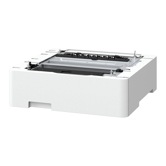
Chapter 2 2.1 Basic Construction 2.1.1 Functional Construction 0010-1723 The finisher additional tray is an option, and is designed as an addition (No. 2 tray) to the finisher's standard tray. It is equipped with an option tray paper sensor (PI12) to detect the presence/absence of paper on it. -
Page 21: Chapter 3 Parts Replacement Procedure
Chapter 3 Parts Replacement Procedure... - Page 23 Contents Contents 3.1 Removing from the Host Machine ........................3-1 3.1.1 Finisher Assembly ............................3-1 3.1.1.1 Removing the Rear Cover ........................3-1 3.1.1.2 Removing the Lower-right Cover ......................3-1 3.1.1.3 Removing the Upper-right Cover......................3-1 3.1.1.4 Removing the shift tray ........................3-1 3.1.1.5 Removing the Finisher .........................
- Page 24 Contents 3.4.5.4 Removing the Bottom Cover of the Optional Tray ................3-6 3.4.5.5 Removing the Optional Tray Drive PCB....................3-6...
-
Page 25: Removing From The Host Machine
Chapter 3 3.1 Removing from the Host Machine 3.1.1.4 Removing the shift tray 0010-6794 1) Disconnect the connectors (J905) [1] and (J906) [2] on the finisher con- troller PCB, and then remove the two binding screws with toothed washer 3.1.1 Finisher Assembly (M3 x 6) [3]. -
Page 26: External Covers
Chapter 3 F-3-7 F-3-9 3.3.1.2 Removing the Rear Cover of the Tray When removing the tray unit, be careful not to get your hands hit or pinched. Do not hold the tray. 0010-6799 1) Remove the two RS tightening screws (M3 x 8) [1], and then detach the rear cover [2] of the tray. -
Page 27: Removing The Bottom Cover Of The Optional Tray
Chapter 3 F-3-15 F-3-12 3.4.1.5 Removing the Stack Tray Paper Surface Detection 3.4.1.2 Removing the Rear Cover of the Tray Sensor 0010-7683 1) Remove the two RS tightening screws (M3 x 8) [1], and then detach the rear cover [2] of the tray. 0010-7686 1) Disconnect the connector [1], and then remove the stack tray paper surface detection sensor [2]. - Page 28 Chapter 3 F-3-21 F-3-18 3.4.3.2 Removing the Tray Guide Top Cover 3.4.2.3 Removing the Stack Tray Assmbly 0010-6815 1) Remove the two RS tightening screws (M3 x 8) [1], and then detach the rear cover [2] of the tray. 0010-7689 1) Holding the stack tray [1], remove it in the direction of the arrow.
-
Page 29: Removing The Lower-Left Cover Of The Optional Tray
Chapter 3 F-3-27 3.4.4 Tray Clock Sensor F-3-24 3.4.4.1 Removing the Stack Tray Assmbly Harness 0010-6801 1) Remove the screw [1], and then remove the sensor mounting plate [2]. 3.4.3.5 Removing the Lower-left Cover of the Optional 2) Remove the harness from the two wire saddles [3], and then remove the Tray reusable band [4]. -
Page 30: Removing The Clock Sensor
Chapter 3 3.4.5.2 Removing the Tray Guide Top Cover 0010-6810 1) Remove the two RS tightening screws (M3 x 8) [1], and then detach the rear cover [2] of the tray. F-3-30 3.4.4.4 Removing the Clock Sensor 0010-6804 1) Remove the harness from the four wire saddles [1] and three mini-clamps F-3-33 [2], and then remove the four binding screws (M3 x 4) [3]. - Page 31 Chapter 3 F-3-36...
-
Page 33: Chapter 4 Maintenance
Chapter 4 Maintenance... - Page 35 Contents Contents 4.1 Maintenance and Inspection ..........................4-1 4.1.1 Periodically Replaced Parts......................... 4-1 4.1.1.1 Periodically Replaced Parts........................4-1 4.1.2 Durables............................... 4-1 4.1.2.1 Durables..............................4-1 4.1.3 Periodical Servicing ............................ 4-1 4.1.3.1 Periodical Servicing..........................4-1 4.2 Variable Resistors (VR), Light-Emitting Diodes (LED), and Check Pins by PCB ........... 4-1 4.2.1 Functions of the DIP Switch ........................
-
Page 37: Maintenance And Inspection
Chapter 4 4.1 Maintenance and Inspection 4.1.1 Periodically Replaced Parts 4.1.1.1 Periodically Replaced Parts 0010-1724 The machine does not have parts that must be replaced on a periodical basis. 4.1.2 Durables 4.1.2.1 Durables 0010-1725 This machine does not have items that may be classified as durables. 4.1.3 Periodical Servicing 4.1.3.1 Periodical Servicing 0010-1726... -
Page 39: Chapter 5 Error Code
Chapter 5 Error Code... - Page 41 Contents Contents 5.1 Service Error Code ............................. 5-1 5.1.1 Service Error Code ............................5-1 5.2 Alam Code................................5-1 5.2.1 Alarm Code List ............................5-1...
-
Page 43: Service Error Code
Chapter 5 5.1 Service Error Code 5.1.1 Service Error Code 0010-1729 T-5-1 Code Detail code Description Timing of detection E542 0001 -The option stack tray motor or the -The optional stack tray has been finisher controller PCB is faulty. driven, but the paper surface is not -The option stack tray home detected. - Page 45 Sep 14 2005...