Makita HM1304 Technical Information
Hide thumbs
Also See for HM1304:
- Instruction manual (37 pages) ,
- Quick manual (8 pages) ,
- Instruction manual (37 pages)
Advertisement
Quick Links
T
ECHNICAL INFORMATION
Models No.
Description
C
ONCEPTION AND MAIN APPLICATIONS
HM1304B is the sister model of HM1304, and hex 28.6mm
(1-1/8") bit can be used with HM1304B.
And this new product conforms to requirements of
the new European noise regulation which will be effective
from 2006.
S
pecification
Voltage (V)
110
120
220
230
240
Blows per min, :(bpm=min
Shank : mm (")
Single blow energy : J
Protection from electric shock
Cord length : m ( ft )
Net weight :Kg (lbs )
S
tandard equipment
* Steel carrying case ............................ 1 pc.
< Note > The standard equipment for the tool shown may differ from country to country.
O
ptional accessories
* Bull point
* Cold chisel
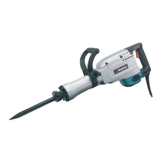
HM1304B
Demolition Hammer
Current (A)
Cycle (Hz)
14.0
50 / 60
13.0
50 / 60
50 / 60
7.2
6.9
50 / 60
6.6
50 / 60
1,450
-1)
28.6 (1-1/8) hex
27.5
by double insulation
5.0 (16.4)
17.0 (37.5)
* Scaling chisel
* Rammer
* Clay spade
Dimensions : mm ( " )
831 (32-3/4)
Length ( L )
Width ( W )
115 (4-1/2)
Height ( H )
219 (8-5/8)
Continuous Rating (W)
Input
Output
1,500
900
900
1,500
900
1,500
900
1,500
900
PRODUCT
P 1 / 12
L
w
Max. Output(W)
1,600
1,600
1,600
1,600
1,600
1,600
H
Advertisement

Related Manuals for Makita HM1304


Summary of Contents for Makita HM1304
- Page 1 Description Demolition Hammer ONCEPTION AND MAIN APPLICATIONS HM1304B is the sister model of HM1304, and hex 28.6mm (1-1/8") bit can be used with HM1304B. And this new product conforms to requirements of the new European noise regulation which will be effective from 2006.
- Page 2 Parts The portion to be lubricated The grease to be applied to be applied: g (oz.) 0.5 (0.02) Inside where contacts hammer bit. MAKITA grease R No.00 Tool holder 0.5 (0.02) MAKITA grease R No.00 O Ring 24 0.5 (0.02) Inside where contacts impact bolt.
- Page 3 P 3 / 12 epair < 2 > Disassembling motor section (1) Remove holder cap plate by unscrewing pan had screw M5x16. Remove rubber ring 6, brush holder cap and carbon brushes. See Fig. 2. (2) Remove handle set from crank housing by unscrewing hex socket head bolts M6x50 and M6x40. However, the handle set can not be separated completely from motor housing in this step, because it is still connected with lead wires.
- Page 4 P 4 / 12 epair < 3 > Assembling motor section (1) Make sure that seal has been previously mounted to armature. Mount armature and then baffle plate to crank housing. See Fig. 7. (2) Make sure that flat washer 18 has been previously mounted in the bearing assembling hole of motor housing (rear cover side).
- Page 5 P 5 / 12 epair < 4 > Removing barrel section from crank housing (1) Take off hex socket head bolts M6x45 and insert slotted head screwdriver into the gap between gear housing cover and gear housing. Lever up gear housing cover with the inserted screwdriver. Then, gear housing cover can be separated from gear housing See Fig.
- Page 6 P 6 / 12 epair < 5 > Removing cylinder liner from barrel (1) Take off hex socket head bolts M8x30 and remove tool holder from barrel. And take off inner parts from barrel. See Fig.15. Urethane ring 48 (2 pcs.) Tool guide Rubber ring 52 Seal holder...
- Page 7 P 7 / 12 epair (2) Take off spring pins 8-40 by striking with hammer as illustrated in Fig. 18. Then, tool retainer section can be disassembled as illustrated in Fig. 18A. Tool retainer shaft Tool retainer Spring pin extractor Tool retainer pole Spring pins 8-40 Tool holder...
- Page 8 P 8 / 12 epair < 8 > Assembling barrel section to crank housing (1) Mount cylinder liner into barrel with arbor press. See Fig.24. And mount the parts to barrel as illustrated in Fig. 25. 1R032 Urethane ring 48 Bearing setting plate Tool guide Idler...
- Page 9 P 9 /12 epair < 9 > Disassembling gear housing section (1) Remove ball bearing 6302 from crank shaft with 1R044 "Small gear extractor". See Fig. 29. (2) Holding bearing box mounted to gear housing, with 2 pcs. of round bars for arbor (approx. Ø30mm) press the crank shaft and remove it from gear housing.
- Page 10 P 10 / 12 epair (4) Aligning the cut portion of helical gear 57 with the woodruff key 4, mount helical gear 57 to crank shaft by pressing crank shaft with arbor press. See Fig. 36. (5) Mount ball bearing 6302 to crank shaft by pressing crank shaft with arbor press. See Fig.
- Page 11 P 11 / 12 epair < 13 > Fastening torque for bolts and screws When assembling, fasten the bolts and screws with the following fastening torque. The parts in crank housing Bearing box Crank shaft Needle bearing 1715 Fig. 41 Hex socket head bolt M8x30 6 pcs.
- Page 12 P 12 / 12 ircuit diagram Color index of lead wires Black White Switch Orange Purple Receptacle Noise Field suppressor Receptacle Power supply cord iring diagram Inside of motor housing Connect receptacles to brush holders so that the lead wires of orange and purple face to the rear cover side as illustration.