Table of Contents
Advertisement
This manual contains safety information, associated manual listings, specifications and terminal layouts
and wiring for Japanese specification FX
For complete operation, mounting and programming instructions please refer to the FX
MANUAL (JY992D87501 JAPANESE ONLY) and PROGRAMMING MANUAL.
These manuals should be read and understood before attempting to install or use the unit.
Guidelines for the Safety of the User and Protection of the FX
This manual has been written to be used by trained and competent personnel. The definition of such a
person or persons is as follows:
a)
Any engineer who is responsible for the planning, design and construction of automatic equipment using the
product associated with this manual, should be of a competent nature, trained and qualified to the local and
national standards. These engineers should be fully aware of all aspects of safety with regards to automated
equipment.
b)
Any commissioning or service engineer must be of a competent nature, trained and qualified to the local and
national standards. These engineers should also be trained in the use and maintenance of the complete
product. This includes being completely familiar with all associated documentation for the said product. All
maintenance should be carried out in accordance with established safety practices
c)
All operators of the completed equipment should be trained to use that product in a safe and co-ordinated
manner in compliance to established safety practices. The operators should also be familiar with documentation
which is connected to the actual operation of the completed equipment
Note: The term 'completed equipment' refers to a third party constructed device which contains or uses
the product associated with this manual.
Note's on the Symbols Used in this Manual
At various times through out this manual certain symbols will be used to highlight points of information
which are intended to ensure the users personal safety and protect the integrity of equipment.
1) Indicates that the identified danger could POSSIBLY cause physical and property damage.
2) Indicates a point of further interest or further explanation.
•
Under no circumstances will Mitsubishi Electric be liable or responsible for any consequential damage
that may arise as a result of the installation or use of this equipment.
•
All examples and diagrams shown in this manual are intended only as an aid to understanding the
text, not to guarantee operation. Mitsubishi Electric will accept no responsibility for actual use of the
productbased on these illustrative examples.
•
Owing to the very great variety in possible application of this equipment, you must satisfy yourself as
to its suitability for your specific application.
Further Information Manual Lists
The following manuals are recommended as essential reference material for the correct operation of an
FX
series Programmable Controller
1N
Manual name
FX
1N
HANDY MANUAL
FX
, FX
, FX
, FX
1S
1N
2N
PROGRAMMING
MANUAL
1N
Manual No.
JY992D87501
(JAPANESE ONLY)
2NC
JY992D62001
(JAPANESE ONLY)
Industrial automation
Elincom Group
EuropeanUnion: www.elinco.eu
Russia: www.elinc.ru
FX
JAPANESE SPECIFICATION UNITS
1N
HARDWARE MANUAL
PLC main units.
Describes contents related to hardware of world
specification FX
specifications, wiring and installation.
Programming manual for FX
FX
series Programmable Logic Controllers
2NC
JY997D07901A
PLC
1N
Description
series PLCs such as
1N
, FX
1S
1N
HANDY
1N
, FX
and
2N
Advertisement
Table of Contents

Related Manuals for Mitsubishi FX1N-24MR


Summary of Contents for Mitsubishi FX1N-24MR
- Page 1 • All examples and diagrams shown in this manual are intended only as an aid to understanding the text, not to guarantee operation. Mitsubishi Electric will accept no responsibility for actual use of the productbased on these illustrative examples. •...
-
Page 2: Specifications
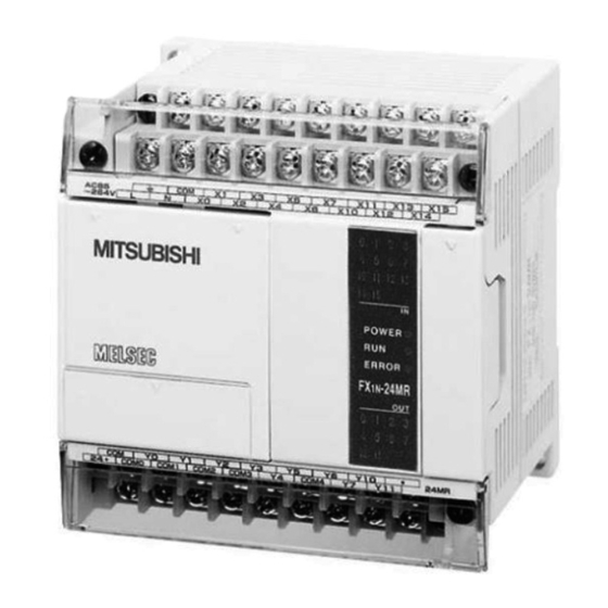
1. Introduction This manual covers basic hardware details for the FX Series Programmable Logic Controller. INPUT OUTPUT POWER DIMENSIONS WEIGHT MODEL SUPPLY mm (inches) kg (lbs) TYPE TYPE -24MR Relay 0.45 (16) (16) (3.6) (0.99) -24MT Transistor 100-240 -40MR Relay 24V DC 0.65 +10%... -
Page 3: Power Specifications
2.1 Power Specifications AC Powered Units -24M -40M -60M Power Supply 100-240V AC +10% -15%, 50-60 Hz Max. allowable momentary power failure 10ms; If less than 10ms, PLC continues operation Fuse (size) rating 250V 1A 250V 3.15A (3A) 100V AC - Max. 30A for 5ms In-rush current 200V AC - Max. -
Page 4: Terminal Layouts
4. Terminal Layouts The following selection of terminal layouts are taken from the FX product range. Note: All layouts are diagrammatic and are only intended to aid the creation of wiring diagrams. 4.1 AC Powered Main Units -24MR / 24MT Y6 Y10 Y7 Y11 COM0 COM1 COM2 COM3... -
Page 5: Example Wiring
5. Example Wiring If during the wiring of these products or associated products concern is felt, please contact a professional electrician who is trained in the local and national standards applicable to the installation site. Wiring cautions • Do not run input signals in the same multicore cable as output signals or allow them to share the same wire. -
Page 6: Additional Information
Manual number : JY997D07901 Manual revision : A Date : November 2002 HEAD OFFICE : MITSUBISHI DENKI BLDG MARUNOUTI TOKYO 100-8310 TELEX : J24532 CABLE MELCO TOKYO HIMEJI WORKS : 840, CHIYODA CHO, HIMEJI, JAPAN Effective November 2002 JY997D07901A... - Page 7 All examples and diagrams shown in this manual are intended only as an aid to understanding the DC allow at least 2mA flow text, not to guarantee operation. Mitsubishi Electric will accept no responsibility for actual use of the Operating Humidity...
- Page 8 COM6 Y21 Y23 COM7 Y25 Y27 HEAD OFFICE : MITSUBISHI DENKI BLDG MARUNOUTI TOKYO 100-8310 TELEX : J24532 CABLE MELCO TOKYO • When using a DC powered unit, the input circuit power supply should be used. If an HIMEJI WORKS : 840, CHIYODA CHO, HIMEJI, JAPAN external 24V DC supply is used, the FX will not operate correctly.